9
MASONRY
INTRODUCTION
Mortar and grout are the cementitious bonding agents that integrate masonry units into masonry assemblies. Because concrete, masonry mortar, and grout contain the same principal components, some design professionals assume good practice for one will also be good practice for another. In reality, the three materials differ in proportions, working consistencies, methods of placement, and structural performance.
Mortar and grout structurally bind masonry units together, whereas concrete is usually itself a structural material. One of the most important functions of concrete elements is to carry load, whereas the principal function of mortar and grout is to develop a complete, strong, and durable bond with masonry units. Concrete is poured into nonabsorbent forms with a minimum amount of water. Mortar and grout are placed, with much more water, between absorptive forms (masonry units). The water/cement ratio of the mix design is very important in concrete work, but it is less important with mortar or grout for masonry. When mortar or grout is placed with masonry units, the water/cement ratio rapidly decreases because of the clay or concrete unit masonry’s absorbency. It is important to distinguish between the requirements for concrete, masonry mortar, and grout.
MASONRY MORTARING AND GROUTING
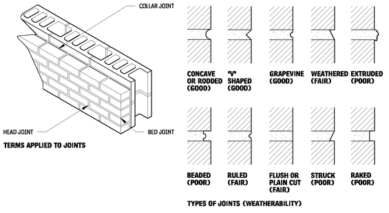
TYPES OF JOINTS
Mortar serves multiple functions:
• Joins and seals masonry, allowing for dimensional variations in masonry units.
• Affects overall appearance of wall color, texture, and patterns.
• Bonds reinforcing steel to masonry, creating composite assembly.
MORTAR JOINT FINISH METHODS
• Troweled: Excess mortar is struck off. The trowel is the only tool used for shaping and finishing.
• Tooled: A special tool is used to compress and shape mortar in the joint.
MORTAR JOINTS
9.1
MASONRY ANCHORAGE, REINFORCING, AND ACCESSORIES
MASONRY ANCHORAGE AND REINFORCING
GENERAL
Masonry construction has not always required the inclusion of metal components. Historically, composite masonry construction consisted of multiple wythes of masonry bonded together by headers. However, contemporary masonry walls require ties between the inner and outer wythes, which are then anchored to the structural frame. Many design professionals use the terms “wall tie” and “anchor” interchangeably; in practice “ties” are of a lightergage material than anchors. Both ties and anchors transfer load to structural framing or other structural members.
Anchors and ties with flexible components may accommodate limited differential movement between the structural frame and the masonry wall by allowing for in-plane movement.
CORROSION PROTECTION
The durability of any metal component is usually based on its ability to resist corrosion. Since masonry walls are often subject to moisture, metal must be protected, either by galvanizing or by the use of corrosion-resistant metals. The following ASTM standards apply to corrosion protection of carbon steel components.
• ASTM A 123, “Standard Specification for Zinc (Hot-Dip Galvanized) Coatings on Iron and Steel Products”
• ASTM A 153, “Standard Specification for Zinc Coating (Hot-Dip) on Iron and Steel Hardware”
• ASTM A 641, “Standard Specification for Zinc-Coated Carbon steel Wire”
• ASTM A 653, “Standard Specification for Steel Sheet, Zinc-Coated (Galvanized) or Zinc-Iron Alloy-Coated (Galvannealed) by the Hot-Dip Process”
Corrosion protection is also provided by stainless-steel anchors and ties conforming to ASTM A 580, for Type 304.
ANCHORS AND REINFORCEMENT
Selection of anchors and reinforcement is determined by the relationship of the masonry element to the structural support.
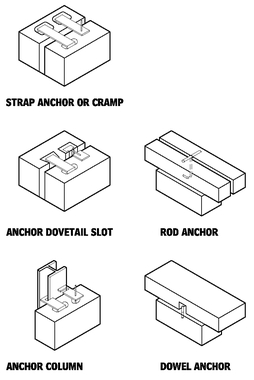
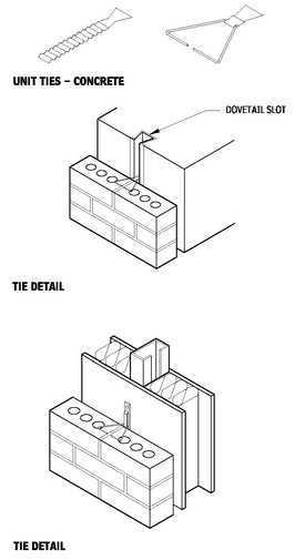
Reinforcing bars may be placed horizontally and vertically in masonry. The reinforcement may be placed in the cores or cells of masonry units or between wythes of masonry. The use of dovetail slots welded on steel or concrete columns requires coordination during the steel or concrete fabrication stage. The type of anchor specified, including its size, diameter, and spacing, should be called out in the construction documents.
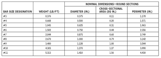
ASTM STANDARD REINFORCING BARS FOR MASONRY
9.2
NOTE
9.2 Bar sizes larger than #11 are not permitted in masonry work.
Contributors:
Grace S. Lee, Rippeteau Architects, PC, Washington, DC; Brian E. Trimble, PE, Brick Industry Association, Reston, Virginia; Stephen S. Szoke, PE, National Concrete Masonry Association, Herndon, Virginia.
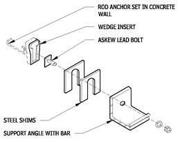
CLIP ANGLE ANCHOR
9.3
ANCHOR TYPES
9.4
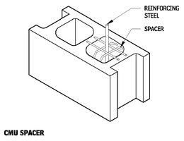
CMU REINFORCING BAR
9.5
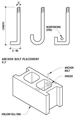
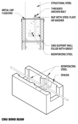
ANCHOR BOLTS
9.6
ANCHOR BOLT TOT
9.8
MASONRY TIES
Masonry ties perform one or more functions:
• Provide a connection.
• Transfer lateral loads.
• Permit in-plane movement to accommodate differential movements.
• May act as horizontal structural reinforcement.
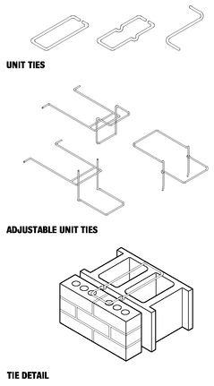
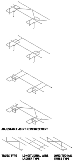
Masonry ties include unit ties, adjustable unit ties, adjustable joint reinforcement, and joint reinforcement.
UNIT TIES FOR MASONRY BACKUP
9.9
NOTES
9.9 a. Z-ties can be used only with solid masonry veneer units.
b. Tie must extend a minimum of 1-1/2 in. onto solid masonry units and be fully embedded in mortar on the outer face shell of hollow masonry units.
Contributor:
Brian E. Trimble, PE, Brick Industry Association, Reston, Virginia.
JOINT REINFORCEMENT FOR MASONRY BACKUP
9.10
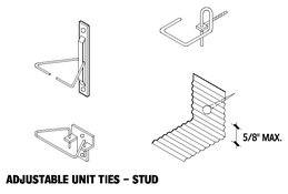
ADJUSTABLE UNIT TIE FOR FRAMING BACKUP
9.11
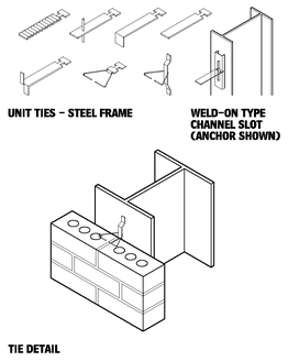
ADJUSTABLE UNIT TIE—STRUCTURAL STEEL BACKUP
9.12
ADJUSTABLE UNIT TIE FOR CONCRETE BACKUP
9.13
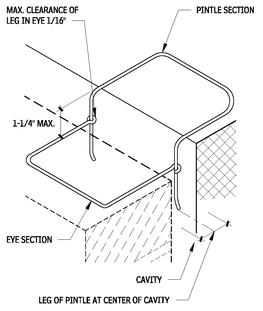
TYPICAL ADJUSTABLE UNIT TIE
9.14
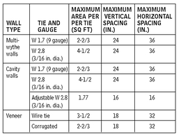
Masonry tie spacing recommendations are included Table 9.22. The ties should be staggered in alternate rows, and only one row of ties should be located in the same bed joint to allow proper embedment in the mortar.
In wall construction in which masonry wythes are built up together and the joints align, a single anchor is laid over both wythes. Where one wythe of masonry is laid up before the other wythe, or when joints do not align, adjustable ties may be necessary. Adjustable ties are advantageous for several reasons:
• Interior wythes can be constructed before the exterior wythe, allowing the structure to be enclosed faster.
• The risk of damage to the ties when the exterior wythe is constructed is reduced.
• Adjustable ties can more readily accommodate construction tolerances.
• Adjustable ties can accommodate larger differential movements.
However, adjustable ties must be installed properly or the tie may be rendered useless. Location of the channel is critical, as the tie must engage the channel and be properly embedded in the exterior wythe.
MASONRY TIE SPACING RECOMMENDATIONS
9.15
NOTES
9.11 Differential movement must always be accounted for wall framing with adjustable ties.
9.15 Consult applicable building codes for spacing requirements and for allowable tie types for various construction. Corrugated ties may not be allowed by code.
Contributor:
Brian E. Trimble, PE, Brick Industry Association, Reston, Virginia.
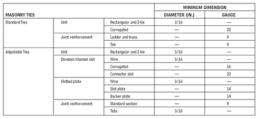
RECOMMENDED MINIMUM TIE DIAMETERS AND GAUGES
9.16
MASONRY ACCESSORIES
MASONRY CAVITY DRAINAGE, WEEPHOLES, AND VENTS
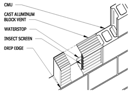
With proper design and installation, weepholes and vents discharge moisture trapped within the wall cavity. Weepholes are required in the head joint of the course of masonry immediately above all embedded flashing, and should be installed at all horizontal interruptions in the wall. Weepholes should never be located below grade and should be small enough to keep out rodents. Weepholes may be open head joints, holes formed with nylon rope or oiled rods, plastic or metal tubes, fibrous rope, cotton sash cord, or cellular material. Open head joints are often fitted with vents or screens to keep out insects or rodents. Formed and tube weepholes should have a minimum diameter of 1/4 inch, though it is important to take into consideration the type of weephole utilized in conjunction with the climate. Open head joints are a preferred type of weephole, occurring no more than 32 in. on center, although in clay unit masonry they should be spaced no more than 24 in. or in. on center. If cord or rope is, the material should be at least 16 in. long. Weepholes other than open head joints should be spaced no more than 16 in. on center.
MASONRY EMBEDED FLASHING Flashing in masonry construction is necessary to collect moisture that enters the wall system and to channel it to the exterior through weepholes. Moisture enters masonry walls through condensation, penetration of wind-driven rains, failed sealant joints, interfaces with other components, or other components themselves, such as windows or roofs.
There are two types of flashing. Exposed flashings can be applied to all masonry construction, while use of embedded flashing is usually limited to drainage-type walls. Masonry is a durable, long-lasting construction material. Thus, the flashing materials selected should also be durable and have a long life, especially embedded flashing materials, which are difficult to replace.
MATERIALS
Flashing may be made of sheet metal (copper, lead, stainless steel, galvanized steel, or aluminum), plastic, or composite materials (usually paper-backed, coated, metallic sheet, or fibrous glass mesh). When selecting flashing materials, avoid those that would have cathodic reactions with mortar, other metals, or other construction materials. The thickness of the flashing material specified should take into account the span between embedment, bends, or connections. Copper may cause a patina, which may be desirable. Lead and galvanized metal may result in some white staining, but this may be minimal if coated materials are used. Choose aluminum as an embedded flashing only if it is properly coated, so it will not react wit the mortar. Polyethylene should not be used as flashing unless it has been chemically stabilized so it will not deteriorate when exposed to sunlight (ultraviolet radiation). Asphalt-impregnated building paper (building felt) is not an acceptable flashing material. Adhered flashings must be held back from the face of the wall to avoid deterioration and staining caused by high temperatures.
INSTALLATION
Embedded flashing is typically used in drainage walls at the base, above all openings, at sills and shelf angles, and under copings. Continuous embedded flashing should be lapped at lease 6 in. and sealed with and appropriate sealer. Discontinuous flashing should have the ends turned up at lease 1 in. to form a dam. Dams prevent water collected on the flashing from draining off the ends of the flashing back into the wall system or into framing or mullions.
Embedded flashing should extend at least 8 in. vertically within the wall system; it should extend at least 1-1/2 in. into the interior wythe and through the exterior wythe at least 1/4 in. to form a drip. The drip minimizes possible staining. Sometimes, it may be necessary to avoid the drip, as with rough textured units and ribbed, scored, or fluted masonry units. The flashing must be carefully brought to the surface of the recessed portion of the masonry. Plastic flashing is often exposed and cut off flush with the face of the masonry. If the flashing is recessed and does not reach the surface, water collected on it may be channeled by mortar under the flashing and back into the wall system.
WEEPHOLE DETAILS
9.17
BRICK OR BLOCK VENT
9.18
GALVANIC CORROSION (ELECTROLYSIS) POTENTIAL BETWEEN COMMON FLASHING MATERIALS AND SELECTED CONSTRUCTION MATERIALS
9.19
NOTES
9.16 Thicker diameters and gauges are available. 9.19
• Galvanic action will occur, hence direct contact should be avoided.
• Galvanic action may occur under certain circumstances and/or over a period of time.
• Galvanic action is insignificant; metals may come into direct contact under normal circumstances.
a. Galvanic corrosion is apt to occur when water runoff from one material comes in contact with a potentially reactive material.
Contributors:
Brian E. Trimble, PE, Brick Industry Association, Reston, Virginia; Grace S. Lee, Rippeteau Architects, PC, Washington, DC; Stephen S. Szoke, PE, National Concrete Masonry Association, Herdon, Virginia.
WOOD BLOCKING AND METAL WALL PLUGS
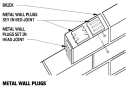
The procedure for attaching other materials, and fixtures, to masonry is relatively simple and can be executed either during or after construction. Fasteners, such as lag bolts and shields, are commonly used because of their flexibility in placement. However, when the precise location of the fastener can be determined during construction, nailing blocks and metal wall plugs are the preferable means of attachment to masonry and are placed in the mortar joints as the masonry is laid.
Wood blocking should be of seasoned softwood to prevent shrinkage and be pressure treated to inhibit deterioration. They should be placed only in the head joint. Metal wall plugs are made of galvanized metal and may contain wooden or fiber inserts. Such plugs may be placed in either the head or bed joints of masonry.
METAL WALL PLUGS
9.20
MASONRY MOVEMENT JOINTS
GENERAL
The various materials and elements used to construct a building are in constant motion. All building materials change in volume in response to internal or external stimuli, such as temperature changes, moisture expansion, and elastic deformation due to loads or creep. Restraining such movements may cause stresses within the building elements, which in turn may result in cracks.
To avoid cracks, the building design should minimize volume change, prevent movement, or accommodate differential movement between materials and assemblies. Masonry control and expansion joints are types of movement joints that minimize cracks in of masonry construction. The design of joints should take into consideration the magnitude of each type of movement that may occur in masonry and other building materials.
MOVEMENTS OF CONSTRUCTION MATERIALS
The design and construction of most buildings does not allow precise movement prediction of building materials. Changes depend on material properties; therefore, they are highly variable. Material age and temperature at installation are two conditions that may also influence movement. When mean values of material properties are used in design, the actual movement may be underestimated or overestimated. Design professionals should use discretion when selecting the applicable values. Table 9.21 indicates the type of movements that affect common building materials.
MOVEMENT JOINTS
There are various types of movement joints in buildings: expansion joints, control joints, separation or isolation joints, and construction joints. Each type of movement joint is designed to perform a specific task; they should not be used interchangeably.
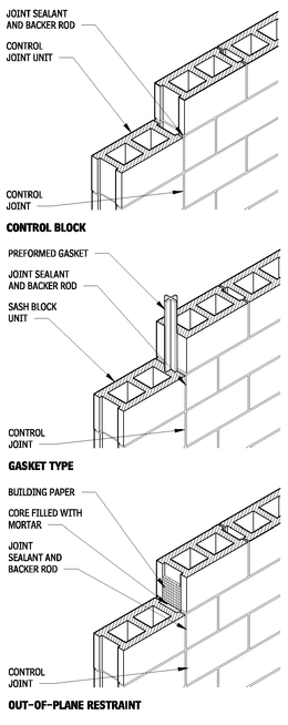
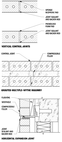
Control joints are used to separate masonry into segments to minimize cracking due to changes in temperature, moisture expansion, elastic deformation due to loads, and shrinkage and creep in concrete-framed buildings. Control joints may be horizontal or vertical. They are formed of elastomeric materials placed in a continuous, unobstructed opening through the masonry wythe. This construc-tion
MOVEMENT OF BUILDING MATERIALS
9.21
CONCRETE UNIT MASONRY CONTROL JOINTS
9.22
allows the joint to compress with movement of materials. Control joints must be located so the structural integrity of the masonry is not compromised.
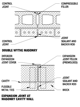
Expansion (isolation) joints are used to separate a building into discrete structural sections so that stresses developed in one section, will not affect the integrity of the entire structure. The Expansion joint is a through-the-building joint, including the roof assembly.
CLAY UNIT MASONRY CONTROL JOINTS
9.23
Contributors:
Grace S. Lee and A. Harris Lokmanhakim, AIA, Rippeteau Architects, PC, Washington, DC; Brian E. Trimble, PE, Brick Industry Association, Reston, Virginia; Stephen S. Szoke, PE, National Concrete Masonry Association, Herndon, Virginia
Separation or isolation joints are joints between dissimilar materials such as openings and adjacent masonry construction. These joints accommodate differential movement in building materials.
MASONRY CONTROL AND EXPANSION JOINTS
9.24
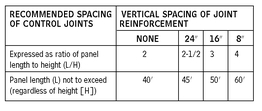
CONTROL JOINT SPACING FOR CONCRETE MASONRY UNITS
9.25
A construction (cold) joint is used primarily in concrete construction when construction work is interrupted. Construction joints are located where they will least impair the strength of the structure.
SPACING OF MASONRY CONTROL AND EXPANSION JOINTS
No single recommendation on the positioning and spacing of control and expansion joints can be applied to all structures. Each building should be analyzed to determine the extent of movement expected within that particular structure. Provisions should be made to accommodate these movements and their associated stresses with a series of control and expansion joints.
Generally, spacing of control joints is determined by considering the amount of expected wall movement and the size of the control joint. Recommended spacing of control joints in concrete unit masonry is addressed in Table 9.25. Control joints are often sized to resemble a mortar joint, usually 3/8 in. to 1/2 in.
Expansion joints may utilize sealant or preformed filler. Maximum sealant joint size is approximately 2 inches with 50 percent movement, thus when expansion joints are over 3 inches in width preformed fillers are common.
Control and expansion joints do not have to be aligned in cavity walls; however, they should be aligned in multiwythe walls.
LINTELS
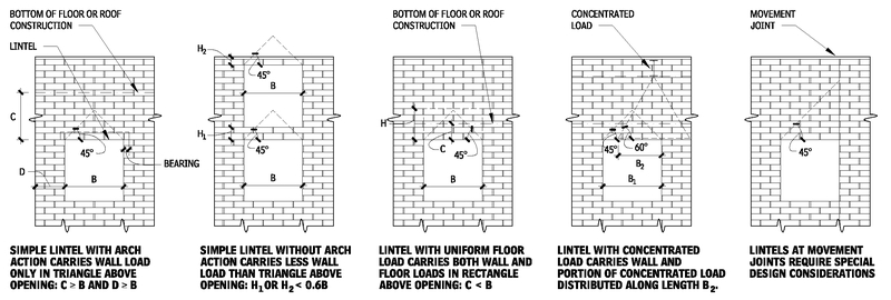
LINTEL LOADING CONDITIONS (CONSULT STRUCTURAL HANDBOOK FOR DESIGN FORMULAS)
9.26
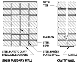
STEEL LINTEL DETAILS
9.27
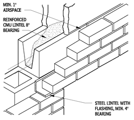
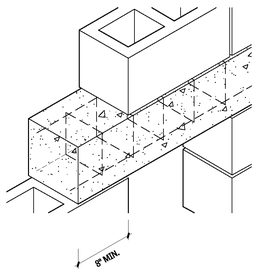
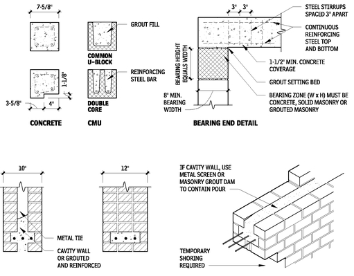
MASONRY LINTEL DETAIL
9.28
PRECAST CONCRETE LINTEL DETAIL
9.29
NOTE
9.27 Steel members to be designed by structural engineer. Flashing details must be designed to suit job conditions.
Contributors:
Grace S. Lee, Rippeteau Architects, PC, Washington, DC; Brian E. Trimble, PE, Brick Industry Association, Reston, Virginia; Stephen S. Szoke, PE, National Concrete Masonry Association, Herndon, Virginia.
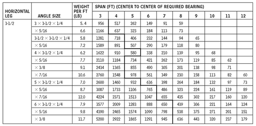
STEEL ANGLE LINTEL SIZING CHART
9.30
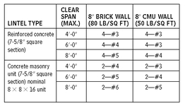
REQUIRED REINFORCING FOR SIMPLY SUPPORTED REINFORCED CONCRETE MASONRY LINTELS
9.31
MAXIMUM DESIGN LOADS FOR PRECAST CONCRETE LINTELS (LB/LINEAR FT)
9.32
UNIT MASONRY
GENERAL
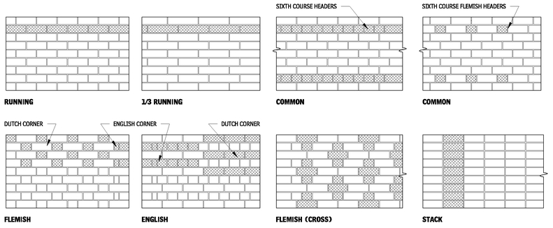
There are various types of bonding patterns that may be used when laying masonry. The most common bond pattern is the running bond for both exposed and unexposed masonry. Combination of various bonds patterns produce more aesthetically interesting construction and may be combined with various types, textures, and colors of masonry. Many of the most common bond patterns are indicated in the figure entitled Common Bond Patterns (Figure 9.33).
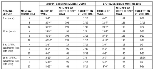
When a curved masonry wall is to be laid up in running bond, the projection of the corners of each unit beyond the face of the units on the courses above and below may need to be limited for aesthetic reasons. Generally, projections of approximately 1/8 in. for nominal 8-inch-long units and 1/4 in. for nominal 16-inch-long units are acceptable. If the wall surface is to be stuccoed or otherwise covered, projections of 1/2 to 3/4 in. may not be objectionable. However, if it is desirable to obtain a smooth appearance for the curve or to limit the shadows created by the projected corners, the projections should not exceed those indicated above. Projections of less than 1/8in. are usually impractical because of construction tolerances. Dependent upon the aesthetic desired, use of other types of bonding patterns may allow for tighter radii, such as a header course in stacked bond. The Minimum Radii of Masonry table (Table 9.34) indicates radii related to the used of running bond patterns and common masonry sizes.
NOTES
9.30 a. Allowable loads to the left of the heavy line are governed by moment, and to the right by deflection. Fy = 36,000 psi. Maximum deflection 1/600. Consult structural engineer for long spans.
b. Allowable uniform loads indicated in pounds per linear foot.
9.31 a. Includes weight of lintel.
b. Wall loads assumed to be 300 lb per linear ft.
c. Floor and roof loads including wall loads assumed to be 1000 lb/linear ft.
d. Eight-inch lintels assumed to weigh 50 lb/ft.
e. Sixteen-inch lintels assumed to weigh 100 lb/ft.
9.32 Lintel properties: width = 7-5/8 in., height = 7-5/8 in., weight = 60 lb/linear ft, f’c = 2500 psi.
Contributors:
Grace S. Lee, Rippeteau Architects, PC, Washington, DC; Brian E. Trimble, PE, Brick Industry Association, Reston, Virginia; Stephen S. Szoke, PE, National Concrete Masonry Association, Herndon, Virginia.
COMMON BOND PATTERNS
9.33
MINIMUM RADII OF MASONRY
9.34
RADIAL WALLS AND BRICK PROJECTIONS
9.35
NOTE
9.34 Interior mortar joints maintained at approximately 1/8 in.
Contributors:
A. Harris Lokmanhakim, AIA, Rippeteau Architects, PC, Washington, DC; Stephen S. Szoke, PE, National Concrete Masonry Association, Herndon, Virginia; Brian E. Trimble, PE, Brick Industry Association, Reston, Virginia.
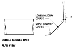
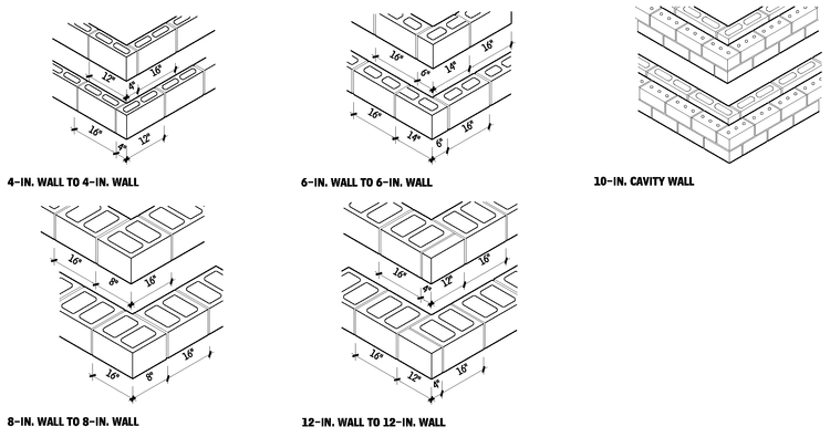
CORNER LAYOUT SHOWING ALTERNATING COURSES
9.36
CLAY MASONRY UNITS
BRICK AND TILE CLASSIFICATION
Brick and tile are classified according to the specific location where they are used. Standard specifications have been developed to produce uniform requirements for brick. ASTM publishes the most widely accepted standards on brick. Standard specifications include strength, durability, and aesthetic requirements.
GENERAL REQUIREMENTS
Terms used in each standard for brick classification may include exposure, appearance, physical properties, efflorescence, dimensional tolerances, distortion, chipping, core, and frogs. Brick may be classified by use, grade (exposure), and type (appearance). Properties should be identified, each ASTM standard has minimum requirements for grade and type, which will be used as the default property if a not specified.
CLAY MASONRY CLASSIFICATION TYPES
9.37
| TYPE OF BRICK UNIT | ASTM DESIGNATION |
|---|
| Building brick | C 62 |
| Facing brick | C 216 |
| Hollow brick | C 652 |
| Paving brick | C 902 |
| Paving brick (heavy vehicular) | C 1272 |
| Ceramic glazed brick | C 126 |
| Thin brick veneer units | C 1088 |
| Sewer and manhole brick | C 32 |
| Chemical-resistant brick | C 279 |
| Industrial floor brick | C 410 |
| TYPE OF TILE UNIT | |
| Structural clay load-bearing tile | C 34 |
| Structural clay nonload-bearing tile | C 56 |
| Structural clay facing tile | C 212 |
| Structural clay nonload-bearing screen tile | C 530 |
| Ceramic glazed tile | C 126 |
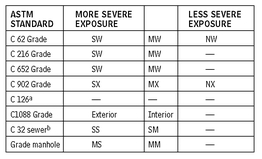
GRADE REQUIREMENTS FOR FACE EXPOSURE
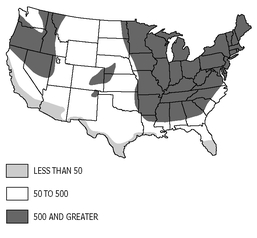
Specific grades of brick are required to accommodate the various climates in the United States and the different applications in which brick can be used. Brick grades include Severe Weathering (SW), Moderate Weathering (MW), and Negligible Weathering (NW), each is based on the weathering index and the exposure they will receive. The weathering index is the product of the average annual number of freezing cycle days and the average annual winter rainfall in inches (see Figure 9.38). The exposure is related to whether the brick is used on a vertical or horizontal surface and whether the unit will be in contact with the earth (see Table 9.39). A higher weathering index or a more severe exposure will require face brick to meet the SW requirements. The grades for each specification are listed in Table 9.39.
U.S. WEATHERING INDEXES
9.38
EXPOSURE
9.39
| | WEATHERING INDEX |
|---|
| EXPOSURE LESS THAN | 50 | 50 AND GREATER |
|---|
| In vertical surfaces | | |
| In contact with earth | MW | SW |
| Not in contact with earth | MW | SW |
| In other than vertical surfaces | | |
| In contact with earth | SW | SW |
| Not in contact with earth | MW | SW |
GRADE REQUIREMENTS FOR FACE EXPOSURES
9.40
NOTES
9.39 See Figure 9.45 for U.S. weathering indexes 9.40 a. No requirements for durability.
b. Based on durability and abrasion.
Contributors:
Grace S. Lee, Rippeteau Architects, PC, Washington, DC; Stephen S. Szoke, PE, National Concrete Masonry Association, Herndon, Virginia; Brian E. Trimble, PE, Brick Industry Association, Reston, Virginia.
COLUMNS, PILASTERS, AND BEAMS
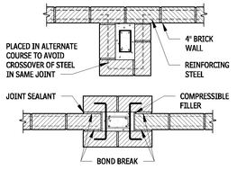
TYPICAL SPECIAL PILASTER UNIT FOR USE WITH CONTROL JOINTS
9.41
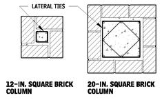
REINFORCED BRICK COLUMNS
9.42
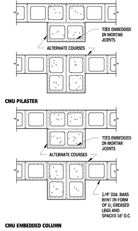
CMU PILASTER AND EMBEDDED COLUMN
9.43
Contributors:
Brian E. Trimble, PE, Brick Industry Association, Reston, Virginia; Stephen S. Szoke, PE, National Concrete Masonry Association, Herndon, Virginia; Grace S. Lee, Rippeteau Architects, PC, Washington, DC.
REINFORCED CLAY MASONRY PILASTERS
9.44
PRECAST CONCRETE AND CMU BEAMS OR LINTELS
9.45
REINFORCED BRICK BEAMS OR LINTELS
9.46
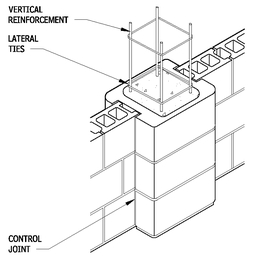
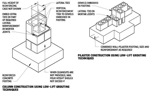
COLUMN AND PILASTER CONSTRUCTION
9.47
LINTEL REINFORCING REQUIRMENTS
9.48
NOTES
9.47 Cut block in first course before laying to form cleanout openings at base of cells to be filled. Remove all mortar droppings, set and inspect vertical reinforcement, and form over opening before filling with grout or concrete. When cleanouts are not provided maximum pour should not exceed 4 ft.
9.48 a. For precast concrete and reinforced concrete masonry unit lintels with no superimposed loads.
b. f’c= 3000 psi concrete and grout; fy = 60,000 psi.
Contributors:
Grace S. Lee, Rippeteau Architects, PC, Washington, DC; Brian E. Trimble, PE, Brick Industry Association, Reston, Virginia; Stephen S. Szoke, PE, National Concrete Masonry Association, Herndon, Virginia
MASONRY ARCHES
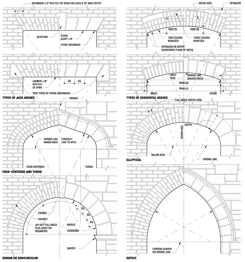
MASONRY ARCHES
9.49
NOTES
9.49 a. Walls, piers, or abutments adjacent to masonry must be of sufficient strength to resist horizontal thrusts.
b. Arch is called “pointed” when radii are equal to span, and called “lancet” when radii are greater than span.
Contributors:
Charles George Ramsey, AIA, and Harold Reeve Sleeper, FAIA, New York City, New York.
GLASS UNIT MASONRY
GLASS BLOCK: DESIGN DATA
GENERAL
Glass block is a diverse building material whose many applications exhibit its multifaceted characteristics. The varying forms of glass block—type, thickness, size, shape, and patterns—along with the method of installation can combine to create unique design solutions. Applications range from entire façades, windows, interior dividers, and partitions to skylights, floors, walkways, and stairways. In all applications, glass block units permit the control of light, both natural and artificial, for function or drama. Glass block also allows for control of thermal transmission, noise, dust, and drafts. Thick-faced glass block or solid 3 in. are impact resistant at assist in security applications.
MORTAR
An optimum mortar mix for installing glass block units is one part portland cement, one-half part lime, and four parts sand. Table 9.50 below gives the number of glass blocks that can be installed at that ratio.
GLASS BLOCK/MORTAR BATCH
9.50
| SERIES | BLOCK SIZEa | BLOCK NUMBERb |
|---|
| Regular | 4 × 8 | 350 |
| 6 × 6 | 350 |
| 8 × 8 | 260 |
| 12 × 12 | 190 |
| Thin | 4 × 8 | 450 |
| 6 × 6 | 450 |
| 8 × 8 | 335 |
TYPES OF BLOCKS
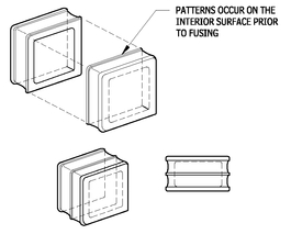
The basic glass block unit is made of two halves fused together with a partial vacuum inside. Units may be transparent, translucent, or opaque, and may be also colored; and patterned. Other options may be available, consult the manufacturer.
SQUARE GLASS BLOCK UNITS
9.51
Glass block is available in thicknesses ranging from a minimum of 3 in. for solid units to a maximum of 4 in. (nominal) for hollow units.
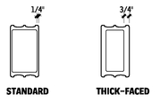
Some manufacturers provide thick blocks for critical applications where a thick-faced, heavier glass block is needed. These blocks have superior sound transmission rating properties, as their faces are three times as thicker than standard units.
BLOCK FACE THICKNESS COMPARISON
9.52
Solar control units have either inserts or exterior coatings to reduce heat gain. Coated units require periodic cleaning to remove alkali and metal ions that can harm the coating. Edge drips are required to prevent moisture rundown on the surface.
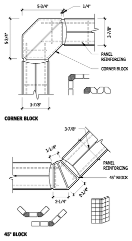
A few manufacturers have special shapes to execute corner designs. These units also may be placed together for varying patterns and forms.
Surface decoration may be achieved with fused-on ceramic, etching, or sandblasting.
SOUND TRANSMISSIONa
9.53
| STC b | SIZE | ASSEMBLY CONSTRUCTION |
|---|
| 31 | 8″ × 8″ × 3″ | Silicone |
| 37c | 8″ × 8″ × 4″ | Mortar |
| 40 | 8″ × 8″ × 4″ with fibrous filter | Mortar |
| 50 | 8″ × 8″ × 4″ thick-faced block | Mortar |
| 53 | 8″ × 8″ × 3″ solid units | Mortar |
GLASS BLOCK INSERT OR COATING
9.54
TYPICAL THERMAL PERFORMANCE/LIGHT TRANSMISSIONa,c
9.55
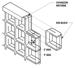
END BLOCK
9.56
NOTES
9.50 a. Includes 15 percent waste.
b. Based on a 1/4-in. exposed joint.
9.53 a. Tested in accordance with ASTM E 90, “Standard Test Method for Laboratory Measurement of Airborne Sound Transmission Loss of Building Partitions and Elements.”
b. STC rating value in accordance with ASTM E 413, “Classification for Rating Sound Insulation.”
c. Test method and STC rating value in accordance with ASTM E 90 and ASTM E 413, accordingly.
9.55 a. Values equal ± 5 percent.
b. Winter night values.
c. To calculate instantaneous heat gain through glass block panels, see ASHRAE Handbook.
d. Based on 8-in. square units: ratio of heat gain through glass block panels versus that through a piece of double-strength monolithic glass under specific conditions.
9.56 End block units have a rounded, finished surface on one edge. They may be used to end interior partitions or walls, or serve as space dividers when installed horizontally.
Contributor:
Grace S. Lee, Rippeteau Architects, PC, Washington, DC.
SPECIAL SHAPES (CORNERS)
9.57
GLASS BLOCK INSTALLATION
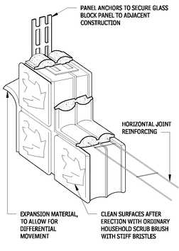
Glass block can be used for both interior and exterior applications; connections to structure and the use of expansion material at the separation joints is critical to ensure glass block panels are not subject to loading from adjacent construction. Both interior and exterior panels must be designed for lateral loads. Glass block can be used in many applications including walls, roofs, and floors.
INSTALLATION REQUIREMENTS
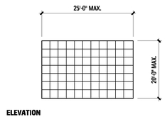
• Area of exterior unbraced panel should not exceed 144 sq ft and 250 sq ft for interior unbraced installations. Refer to Figure 9.59 for maximum dimension.
• Indicated maximum exterior panel sizes are based on a design wind load of 20 lb./sq ft with a 2.7 safety factor. Evaluate panel sized and design wind load for specific projects.
• Panels are designed to be mortared at sill, with head and jambs providing for movement and settling. Deflection of lintel at head should be anticipated.
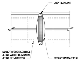
• Movement joints should be installed at change of direction of a multicurved wall, at points of curved wall intersection with straight walls, and at center of curvature in excess of 90 degrees.
• Consult manufacturers for specific design limitations of glass block panels. Thickness of block used also determines maximum panel size.
GLASS BLOCK PANELS
9.58
MAXIMUM PANEL DIMENSIONAL
9.59
GLASS BLOCK PANEL COMPONENTS
9.60
GLASS BLOCK CONTROL JOINT
9.61
NOTE
9.60 Full bed of mortar typically 1/4 in. wide at face of wall. Mortar to be type S optimum mixture: one part portland cement, one-half part lime, four parts sand.
Contributor:
Grace S. Lee, Rippeteau Architects, PC, Washington, DC.
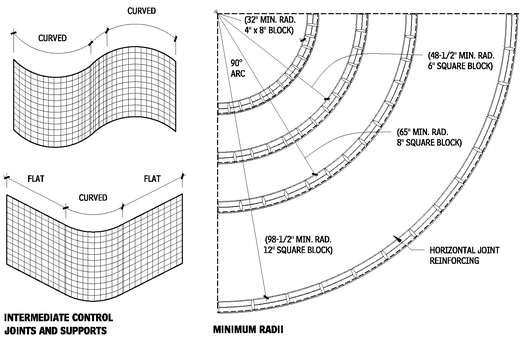
RADIUS MINIMUMS FOR CURVED PANEL CONSTRUCTION
9.62
CURVED PANEL CONSTRUCTION
9.63
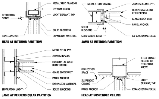
INTERIOR CONNECTION DETAILS
9.64
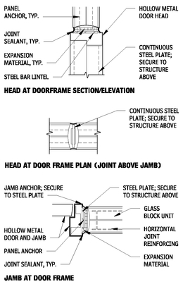
DOOR FRAME DETAILS
9.65
NOTES
9.63 a. It is suggested that curved areas be separated from flat areas by intermediate control joints and supports, as indicated in these drawings.
b. When straight ladder-type reinforcing is used on curved walls, the innermost parallel wire may be cut periodically and bent to accommodate the curvature of the wall.
Contributor:
Grace S. Lee, Rippeteau Architects, PC, Washington, DC.
STONE ASSEMBLIES
STONE USES AND PROPERTIES
GENERAL
Stone assemblies include both natural and cut stone that can be used in many construction applications. The major factors affecting the suitability and use of stone for construction fall under two broad, but overlapping, categories: physical and structural properties and aesthetic qualities. The three factors of building stone that most influence its selection by design professionals for aesthetic reasons are pattern, texture, and color. Consideration also should be given to cost, availability, weathering characteristics, physical properties, and size limitations.
Stone patterns are highly varied, and provide special features that make building stone a unique material. Texture ranges from coarse fragments to fine grains and crystalline structures. Texture also varies with the hardness of minerals composing the stone. To accurately compare stone colors, the rock color chart published by the Geological Society of America (Boulder, Colorado) is recommended. Samples also may be used to establish acceptable color ranges for a particular installation.
Pattern, texture, and color all are affected by how the stone is fabricated and finished. Granites tend to hold their color and pattern, whereas limestone color and pattern change with exposure. Textures may range from rough and flamed finishes to honed or polished surfaces. The harder the stone, the better it takes and holds a polish.
Stone is obtained by quarrying and has two general shapes: cut and rubble.
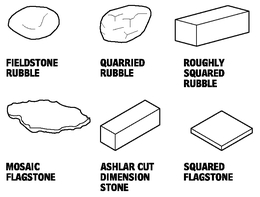
• Rubble is irregular in size and shape. Collected natural stone includes excavated stone, field stone and riverbed stone, it may be weathered smooth, but remains irregular and uneven. The second type of rubble, quarry rubble, includes the fragments of stone left over from the cutting and removal of large stone slabs at the quarry. It has freshly broken faces, which may be sharp and angular.
• Cut stone is either dimension stone or cleft-faced stone. Cut stone is delivered from fabricators who have cut and dressed the stone to a specific size, squared to dimension each way, and to a specific thickness. Surface treatments include a rough or natural split face, smooth, slightly textured, or polished finishes. Ashlar is a type of flat-faced dimension stone, generally in small squares or rectangles, with sawed or dressed beds and joints, while dimension stone is typically larger blocks.
PHYSICAL PROPERTIES OF STONE
The physical characteristics of a particular stone must be suitable for its intended use. It is important to determine the physical properties of the actual stone being used rather than using values from a generic table, which can be very misleading. Considerations of the physical properties of the stone being selected include modulus of rupture, shear strength, coefficient of expansion, creep deflection, compressive strength, modulus of elasticity, moisture resistance, and weatherability.
In addition to accessibility and ease of quarrying, building stone must satisfy requirements for strength, hardness, workability, porosity, durability, and appearance.
• Typically, the compressive strength of building stone is many times higher than required by the loads imposed on it in contemporary construction. Flexural and shear strength are relatively low. Both compressive strength and hardness are proportional to silica content.
• Hardness of stone is critically important only in horizontal planes such as flooring and paving, but hardness does have a direct influence on workability. Characteristics may vary from soft sandstone, which is easily scratched, to very hard stones such as granite.
• Workability refers to the ease with which a stone may be sawed, shaped, dressed, or carved, and will directly affect the cost of production. Workability decreases as the percentage of silica increases. Limestone, for instance, which contains little silica, is easily cut, drilled, and processed. Granite, in contrast, has a high silica content, and is the most difficult stone to cut and finish.
• Porosity, the percentage of void content, affects a stone’s absorption of moisture, thus influencing its ability to withstand frost action and repeated freeze/thaw cycles. Pore spaces are usually continuous, and often form microscopic cracks of irregular shape. Sandstone and limestone are more porous than granite and marble. Due to its porosity, stone selection should take into consideration both application and adjacent construction materials, such as sealant, that may cause staining of the stone.
• Closely linked to porosity are grain and texture, which influence the ease with which stones may be split, and for ornamental purposes contribute to aesthetic effects as much as color.
• Durability of stone, or its resistance to wear and weathering, is also considered analogous to silica content. This is perhaps the most important characteristic of stone because it affects the life span of a structure. Granite is more durable than other building stones because it contains more silica.
In terms of practicality and long-term cost, durability is the most important consideration in selecting building stones. Suitability will depend not only on the characteristics of the stone but also on local environmental and climatic conditions. Water is the most active agent in the destruction of stone. In warm, dry climates, almost any stone may be used with good results. Stones of the same general type such as limestone, sandstone, and marble differ greatly in durability based on softness and porosity. Soft, porous stones are more liable to absorb water and to flake or deteriorate in heavy frosts, and may not be suitable in the colder and moister northern climates.
Most stone used for exterior building construction is relatively volume-stable, returning to its original dimensions after undergoing thermal expansion and contraction through a range of temperatures. Some fine-grained, uniformly textured, relatively pure marbles, however, retain small incremental volume increases after each heating cycle. Marble is actually composed of layers of crystals, and repeated thermal and moisture cycles tend to make these crystals loosen and slide apart. The marble becomes less dense when it expands during heating, but does not return to its prior state during the cooling cycle. This irreversible expansion is called hysteresis. In relatively thick veneers, the greater expansion on the exposed exterior surface is restrained or accommodated by the unaffected interior mass. In thin veneers, however, dilation of the surface region can easily overcome the restraint of the inner layers, causing a “dishing” effect because the greatest expansion is across the diagonal axis. Expansion of the exterior face of marble panels also increases the porosity of the stone and its vulnerability to attack by atmospheric acids and cyclic freezing.
TYPES OF STONE
The three rock classes are igneous, sedimentary, and metamorphic. Despite their abundant variety, relatively few types of stone are suitable as building materials. Granite, marble, limestone, sandstone, and slate are the most common building stones in the United States. Many others, such as quartzite and serpentine, are used locally or regionally, but to a much lesser extent.
GRANITE
Granite is an igneous rock composed primarily of silica quartz, feldspar, mica, and hornblende. Colors vary from red, pink, brown, buff, gray, and cream to dark green and black. Granite is classified as fine, medium, or coarse grained. It is very hard, strong, and durable, and is noted for its weathering and abrasion resistance. Compressive strength may range from 7700 to 60,000 psi, but ASTM C 615, “Standard Specification for Granite Dimension Stone” requires a minimum of 19,000 psi for acceptable performance in building construction. While the hardness of the stone lends itself to a highly polished surface, it also makes sawing and cutting very difficult. Granite is used for flooring, paneling, veneer, column facings, stair treads, flagstones, and in landscape applications. Carving or lettering on granite, which was formerly done by hand or pneumatic tools, is now performed by, computer-assisted stonecutting equipment to achieve a high degree of precision.
LIMESTONE
Limestone is a sedimentary rock, which is durable and easily worked. It consists chiefly of calcium carbonate, but many contain magnesium carbonates in varying proportions, sand or clay, carbonaceous matter, or iron oxides, which may color the stone. The most “pure” form is crystalline limestone, in which calcium carbonate crystals predominate, producing a fairly uniform white or light gray stone of smooth texture. It is highest in strength and lowest in absorption of the various types of limestone. Dolomitic limestone is somewhat crystalline in form, and has a greater variety of texture. Oolitic limestone is noncrystalline, has no cleavage planes, and is very uniform in composition and structure.
The compressive strength of limestone varies from 1800 to 28,000 psi, depending on the silica content. ASTM C 568, “Standard Specification for Limestone Dimension Stone” classifies limestone in three categories : I (low-density); II (medium-density); and III (high-density), with minimum required compressive strengths of 1,800, 4,000, and 8,000 psi, respectively. Limestone is much softer, more porous, and more absorptive than granite. Although it is quite soft when first taken from the ground, limestone weathers hard upon exposure. Its durability is greatest in drier climates.
Impurities affect the color of limestone. Iron oxides produce reddish or yellowish tones, while organic materials such as peat give a gray tint. Limestone textures are graded as:
• A - Statuary
• B - Select
• C - Standard
• D - Rustic
• E - Variegated
• F - Old Gothic
Grades A, B, C, and D come in buff or gray, and vary in grain from fine to coarse. Grade E is a mixture of buff and gray, and is of unselected grain size. Grade F is a mixture of D and E and includes stone with seams and markings.
Limestone is used as cut stone for veneer, caps, lintels, copings, sills, and moldings, and as ashlar with either rough or finished faces. Veneer panels or slabs may be sliced in thicknesses ranging from 1 in. to 6 in. and face sizes from 3 ft by 5 ft to 5 ft by 14 ft. As panel size increases, panel thickness must increase as well. Collected and quarry rubble are often used as rustic veneers on residential and low-rise commercial buildings. Travertine is a porous limestone characterized by small pockets or voids. The pockets common to travertine may be filled to provide a consistent surface, prior to polishing. This natural and unusual texturing presents an attractive decorative surface highly suited to facing materials and veneer slabs.
The denser varieties of limestone, including travertine, can be polished, and for that reason are sometimes classed as marble. The dividing line between limestone and marble is often difficult to determine.
MARBLE
Marble is a crystallized, metamorphosed form of noncrystalline limestone or dolomite. Its texture is naturally fine, permitting a highly polished surface. Marble is found in a wide range of colors, and its crystalline structure adds depth and luster to a polished surface. Pure marbles are white, without the pigmentation caused by mineral oxides. Brecciated marbles are made up of angular and rounded fragments embedded in a colored paste or cementing medium.
Marble often has compressive strengths as high as 20,000 psi, and when used in dry climates or in areas protected from precipitation, the stone is quite durable. Some varieties, however, deteriorate by weathering or exposure to industrial fumes and are suitable only for interior work. ASTM C 503, “Standard Specification for Marble Dimension Stone (Exterior)” covers four marble classifications, each with a minimum required compressive strength of 7500 psi: I, Calcite; II, Dolomite; III, Serpentine; and IV, Travertine. More than 200 imported and domestic marbles are available in the United States. Each has properties and characteristics that make it suitable for different types of construction.
Contributor:
Christine Beall, NCARB, CCS, Austin, Texas.
Marbles are classified as A, B, C, or D on the basis of working qualities, uniformity, flaws, and imperfections. For exterior applications, only group A, highest-quality materials should be used. The other groups are less durable and therefore less suitable for use in exterior unprotected areas. Group B marbles have less favorable working properties than Group A, and will have occasional natural faults requiring limited repair. Group C marbles have uncertain variations in working qualities; contain flaws, voids, veins, and lines of separation; and will always require some repair (known as sticking, waxing, filling, and reinforcing). Group D marbles have an even higher proportion of natural structural variations requiring repair, and have great variation in working qualities.
Marble is available as rough or finished dimension stone, as thin veneer slabs for wall and column facings, flooring, partitions, tiles, and other decorative surface work. Veneer slabs may be cut in thicknesses from 3/4 in. to 2 in. Light transmission and translucence diminish as thickness increases.
SLATE
Slate is a metamorphic rock, formed from sedimentary deposits of clay and shale. Slates containing large quantities of mica are stronger and more elastic than clay slates. The texture of slate is fine and compact, with very minute crystallization. It is characterized by distinct cleavage planes, permitting easy splitting of the stone into slabs 1/4 in. or more in thickness. Used in this form, slate provides an extremely durable material for flooring, roofing, sills, stair treads, and facings. ASTM C 629, “Standard Specification for Slate Dimension Stone” requires that both Type I exterior and Type II interior slate have a minimum modulus of rupture of 9000 psi across the grain, and 7200 psi along the grain.
Small quantities of other mineral ingredients give color to the various slates. Carbonaceous materials or iron sulfides produce dark colors such as black, blue, and gray; iron oxide produces red and purple; and chlorite produces green tints. “Select” slate is uniform in color and more costly than “ribbon” slate, which contains stripes of darker colors.
SANDSTONE
Sandstone is a sedimentary rock formed of sand or quartz grains. Its hardness and durability depend primarily on the type of cementing agent present. If cemented with silica and hardened under pressure, the stone is light in color, strong and durable. If the cementing agent is largely iron oxide, the stone is red or brown, and is softer and more easily cut. Lime and clay are less durable binders subject to deterioration by natural weathering. Sandstone can be categorized by grain size and cementing agent. Siliceous sandstone is cemented together with silica. Many siliceous sandstones contain iron, which is oxidized by acidic pollutants (or acidic cleaners), which turn the stone brown. Ferruginous sandstone is cemented together with iron oxide, so it is naturally red to deep brown in color. Calcareous sandstone is cemented together with calcium carbonate, which is sensitive to acids and can deteriorate rapidly in a polluted environment. Dolomitic sandstone is cemented together with dolomite, which is more resistant to acid. Argillaceous sandstone contains large amounts of clay, which can quickly deteriorate simply from exposure to rain.
FORMS OF BUILDING STONE
9.66
ASTM C 616, “Standard Specification for Quartz-Based Dimension Stone” includes three stone classifications. Type I, sandstone, is characterized by a minimum of 60 percent free silica content; Type II, quartzite sandstone, by 90 percent free silica; and Type III, quartzite, by 95 percent free silica content. As a reflection of these varying compositions, minimum compressive strengths are 2000 psi, 10,000 psi, and 20,000 psi, respectively. Absorption characteristics also differ significantly, ranging from 20 percent for Type I to 3 percent for Type II and 1 percent for Type III. When first taken from the ground, sandstone contains large quantities of water, which make it easy to cut. As the moisture evaporates, the stone becomes considerably harder.
Sandstones vary in color from buff, pink, and crimson to greenish brown, cream, and blue-gray. Both fine and coarse textures are found, some of which are highly porous and therefore low in durability. The structure of sandstone lends itself to smooth and textured finishes for cut stone typically used in veneers, moldings, sills, and copings. Sandstone is also available in rubble masonry.
FINISHES
Much of the stone that is produced for building construction has a sawn finish, but stone may also be further dressed with hand or machine tools for hammered finishes, polished finishes, honed or rubbed finishes. Honing is accomplished by rubbing the stone surface with an abrasive after it has been planed. Larger surfaces are done by machine, smaller surfaces and moldings by hand. Polished surfaces require repeated rubbing with increasingly finer abrasives. Only granite, marble, and some very dense limestones will take and hold a high polish. Power-driven lathes have been developed for turning columns, balusters, and other members that are round in section.
Hand-tooling is the oldest method of stone dressing. Working with pick, hammer, and chisels, the mason dresses each successive face of a stone, giving it the desired finish and texture. Hand-applied finishes include the bush-hammered, patent-hammered, pick-pointed, crandalled, and peen-hammered surface. Many of these finishes are now applied with pneumatic rather than hand tools, resulting in a more uniform surface. Ornate carving is still done by hand, both for new construction and for restoration and rehabilitation projects, although it is sometimes aided by pneumatic chisels.
Granite can be fabricated with a flame cut, or thermal finish to produce a fractured surface texture. It is most often selectively applied to portions of a surface to contrast with polished finish areas.
STONE MASONRY PATTERNS AND VENEER
NOTES
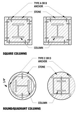
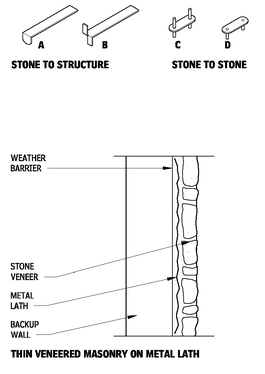
• Structural bond refers to the physical tying together of load-bearing and veneer portions of a composite wall. Structural bond can be accomplished with metal ties or with stone units set as headers into the backup.
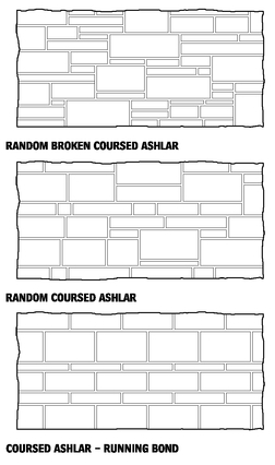
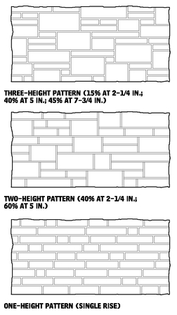
• Ashlar masonry is composed of squared-off building stone units of various sizes. Cut ashlar is dressed to specific design dimensions at the mill. Ashlar is often used in random lengths and heights.
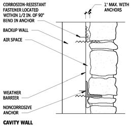
• Ties and anchors must be made of noncorrosive material. Chromium-nickel stainless steel Types 302 and 304 and eraydo alloy zinc are the most resistant to corrosion and staining. Use stainless steel Type 316 in highly corrosive environments. Copper, brass, and bronze will stain under some conditions. Local building codes often govern the types of metal that may be used for stone anchors.
• Nonstaining cement mortar should be used on porous and light-colored stones. At corners use extra ties and, when possible, larger stones. Joints for rough work are usually 1/2 in. to 1-1/2 in. and 3/8 to 3/4 in. for ashlar. Prevent electrochemical reaction between different metals combined in the same assembly by properly isolating or coating them.
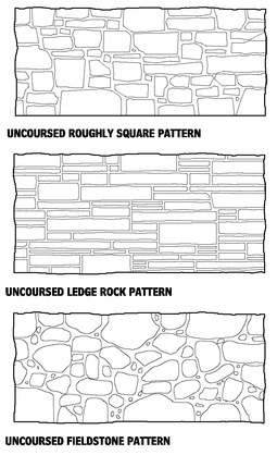
RUBBLE STONE MASONRY PATTERNS—ELEVATIONS
9.67
Contributors:
The McGuire & Shook Corporation, Indianapolis, Indiana; Christine Beall, NCARB, CCS, Autsin, Texas.
CUT STONE MASONRY PATTERNS—ELEVATIONS
9.68
CUT STONE MASONRY HEIGHT PATTERNS—ELEVATIONS
9.69
INSTALLATION DETAILS
9.70
ANCHORS
9.71
TYPICAL STONE VENEER SECTIONS
9.72
Contributors:
George M. Whiteside, III, AIA, and James D. Lloyd, Kennett Square, Pennsylvania; Building Stone Institute, New York City, New York; Alexander Keyes, Rippeteau Architects, PC, Washington, DC; Christine Beall, NCARB, CCS, Austin, Texas.
STONE DETAILS
TYPICAL STONE JOINT DIMENSIONS
9.73
RUSTICATED JOINTS
9.74
TYPICAL JOINT PROFILES
9.75
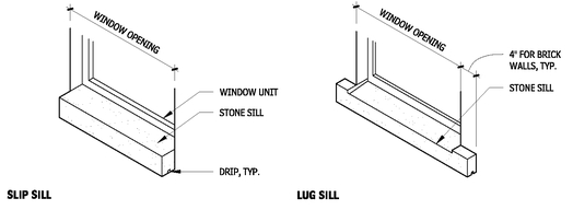
STONE SILL TYPES
9.76
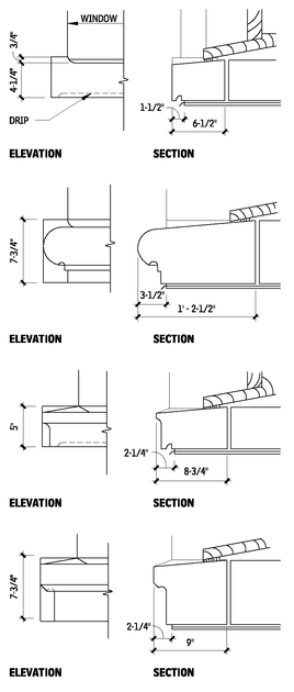
STONE LUG SILL PROFILES
9.77
SEE ALSO
Architectural Concrete Unit Masonry
Clay Unit Masonry
Concrete Unit Masonry
Glass Unit Masonry
Masonry Anchorage and Reinforcing
Masonry Cavity Drainage, Weepholes, and Vents
Masonry Control and Expansion Joints
Masonry Embedded Flashing
Masonry Grouting
Masonry Mortaring
Prefaced Concrete Unit Masonry
Stone Assemblies
Unit Masonry
Contributor:
Christine Beall, NCARB, CCS, Austin, Texas.
