13
INCLUSIVE DESIGN
INTRODUCTION
Inclusive design is an umbrella that acknowledges the diversity of human beings and in the process embraces a number of positions in relationship to people with disabilities and the built environment. Some positions are mandated and some are advocated (driven by public demand). The litany of terminology describing these positions can be perplexing and lead to an ineffectual blurring of the critical differences in meaning, derivation, and approach; therefore, a number of relevant terms are defined here as a preface to the discussions presented in this chapter:
• Universal design: “The design of products and environments to be usable by all people, to the greatest extent possible, without the need for adaptation or specialized design.” (Ron Mace, architect and founder of the Center for Universal Design)
• Accessible design: Design focused on people with disabilities (primarily people with physical and sensory limitations) as a percentage of the population. Minimum standards are mandated via building codes and regulations, technical standards, and civil rights laws such as the Americans with Disabilities Act (ADA) and the Fair Housing Amendments Act (FHAA).
• Americans with Disabilities Act (ADA): Federal civil rights law that prohibits discrimination on the basis of disability in employment, state and local government, places of public accommodation, transportation, and telecommunications. The ADA includes the Standards for Accessible Design.
• Fair Housing Act: Civil rights law that prohibits discrimination in housing on the basis of race, color, religion, sex, disability, familial status, and national origin. The Fair Housing Amendments Act includes the Fair Housing Accessibility Guidelines.
Many architects currently think that universal design and accessibility are synonymous. In fact, universal design is not accessibility, although it is underpinned by accessibility codes and standards, as well as all other required codes and standards. Accessibility standards use a prescriptive, technical approach based on a percentage framework required by law. Universal design is an approach to good design, which posits that by considering the full range of human ability across our lifetimes (small/big, young/old, with varying abilities across every size, every stage of life), we can design better environments for everyone.
This chapter will explain the differences and relationship between two very different approaches to design: one that addresses the full range of human experience and abilities, and is subsequently a condition of sustainability; the second that is derived from a percentage mentality and is subsequently more narrowly focused.
Contributors:
Karen J. King, RA, University of New Mexico, Albuquerque, New Mexico;
Rebecca Ingram Architect, Albuquerque, New Mexico.
UNIVERSAL DESIGN
Our individual physical realities are in a constant state of change across the human lifetime. We are not static. We are young and old, with many shades of in-between; we are small and big, with many variations; we are every ethnicity, in many combinations; we possess all abilities, with infinite variations. Our lives are constituted of differing and changing cadence. This is normal for our species, occurring naturally as well as by our exercise of free will. To design universally is to design for the human experience of the built environment.
The movement toward a design process that puts human experience at the beginning is not new. Universal design is most successful when fully integrated within a project, rendering it invisible and untitled. Its underpinnings as a design movement are attributed to a correlation between improved functional capability and the removal of barriers in the built environment. In the 1970s, architect Michael Bednar suggested that the value in this correlation extends to all of us, not just the few. In the 1980s, Mace would define and give the movement its name and become one of its most recognizable faces. “Universal design is the design of products and environments to be usable by all people, to the greatest extent possible, without the need for adaptation or specialized design.”
In the 1990s, Mace worked with a group of fellow advocates and designers (architects, product designers, engineers, and environmental design researchers) to create the Principles of Universal Design, providing a first step for increasing markets through the design of more widely usable products and environments. This marked a significant shift away from the prescriptive technical approach delineated in codes and standards and established an alternative performance-based criteria focused on issues of usability.
The seven principles establish baseline performance criteria for a wide range of designed products and conditions. They still serve very well in many instances where a one-to-one correlation between improved functional capability and the removal of barriers can readily be employed and discerned. However, the making and experience of architecture rarely presents a one-to-one correlation. The assembly of a spatial experience described by materials and products often results in a more complex overlay of multiple principles and the emergence of universal attributes that expand the scope of the original seven principles. The authors of the original principles recognized that they were establishing an evolving
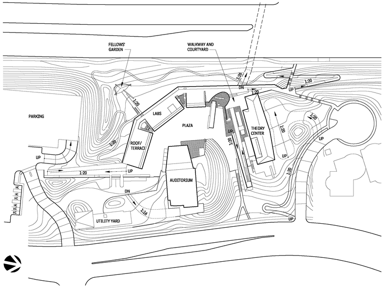
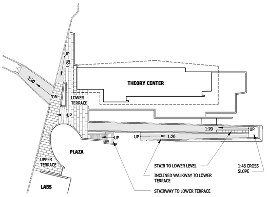
SITE PLAN WITH INTEGRATED UNIVERSAL CIRCULATION
13.1
Source: Tod Williams Billie Tsien Architects, New York City, New York.
Contributors:
Karen J. King, RA, University of New Mexico, Albuquerque, New Mexico; Rebecca Ingram Architect, Albuquerque, New Mexico.
SECTION AT CARVED-IN COURTYARD WITH TERRACE ABOVE
13.2
Source: Tod Williams Billie Tsien Architects, New York City, New York.
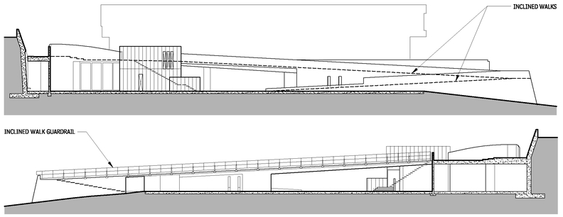
INCLINED WALKWAY—EAST ELEVATION AT LABS
13.3
Source: Tod Williams Billie Tsien Architects, New York City, New York.
framework that could expand as each discipline seized upon and expanded the opportunities inherent in the original intent.
In keeping with the original intent (“ . . . usable by all people, to the greatest extent possible, without the need for adaptation or specialized design”), the attributes of universal design presented here are sometimes a clean fit with the existing principles—sometimes a complex overlay and sometimes emergent. The presentation in this chapter of a particular attribute does not ensure that the project meets every principle or complies with every required code or standard that underpins it. Rather, the principles are presented as examples of critical thinking and detail execution that result in architectural experiences that enrich our lives—all our lives.
SEVEN PRINCIPLES OF UNIVERSAL DESIGN
PRINCIPLE ONE: EQUITABLE USE
The design is useful and marketable to people with diverse abilities.
• Provide the same means of use for all users: identical whenever possible; equivalent when not.
• Avoid segregating or stigmatizing any users.
• Make provisions for privacy, security, and safety equally available to all users.
• Make the design appealing to all users.
EXAMPLE: NEUROSCIENCES INSTITUTE
Tod Williams, FAIA and Billie Tsien, AIA blend ideas of program, topography, and motion in their design for the Neurosciences Institute in La Jolla, California. The buildings enclose a public outdoor space, into which a scientific auditorium is inserted. The auditorium, together with its planted berm, operates in a richly combined manner to set up one of the entries into the plaza, being read as an object, defining closure, and directing view. A series of inclined walks (1:20 or less) both take advantage of existing topographies and invent new ones, while connecting places internal (the plaza and the terraces above the labs) and external (parking and the Scripps Institute under the major roadway).
A laboratory building and one end of the theory building are carved into the topography to form an inhabitable retaining wall bordering the road above.
The inclined walks, along with a variety of stairs, are an integral part of a circuit designed to be a journey of discussion, contemplation, and discovery—a journey that anyone can take. As a matter of “ethics and aesthetics,” the architects have seamlessly integrated universal access into a tectonic essay on movement, creating an ever-changing spatial experience.
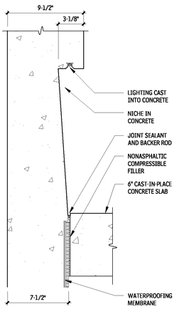
INTEGRATED LIGHTING—INCLINED WALKWAY (TYPICAL)
13.4
Source: Tod Williams Billie Tsien Architects, New York City, New York.
NOTE
13.4 All concrete this sheet to be sandblasted and sealed.
Contributors:
The Principles of Universal Design, North Carolina State University, Center for Universal Design, 1997. Compiled by advocates: Bettye Rose Connell, Mike Jones, AIA, Ron Mace, Jim Mueller, Abir Mullick, Elaine Ostroff, Honorary AIA, John Sanford, Ed Steinfeld, Molly Story, and Gregg Vanderheiden. Major funding provided by the National Institute on Disability and Rehabilitation Research, U.S. Department of Education.
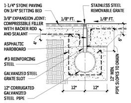
GRATE AND DRAIN DETAIL—AUDITORIUM PLAZA (TYPICAL AT INCLINED WALKWAYS)
13.5
Source: Tod Williams Billie Tsien Architects, New York City, New York.
INCLINED WALK ELEVATIONS—THEORY BUILDING
13.6
Source: Tod Williams Billie Tsien Architects, New York City, New York.
INCLINED WALKWAY—TERRACE-LEVEL PLAN
13.7
Source: Tod Williams Billie Tsien Architects, New York City, New York.
AUDITORIUM PLANS WITH INCLINED WALKS
13.8
Source: Tod Williams Billie Tsien Architects, New York City, New York.
NOTE
13.8 Inclined walkways continue in the scientific auditorium, connecting the upper and lower level seating.
INCLINED WALKWAY AND VESTIBULE SECTION WITH BENCHES—AUDITORIUM
13.9
Source: Tod Williams Billie Tsien Architects, New York City, New York.
PRINCIPLE TWO: FLEXIBILITY IN USE
The design accommodates a wide range of individual preferences and abilities.
• Provide choice in methods of use.
• Accommodate right- or left-handed access in use.
• Facilitate the user’s accuracy and precision.
• Provide adaptability to the user’s pace.
EXAMPLE: SCHALL RESIDENCE
Passing through the big wall and arriving at the car court of the Schall house reveals a hidden realm, an oasis in the desert climate of Phoenix, Arizona.
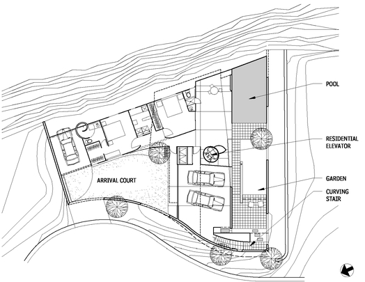
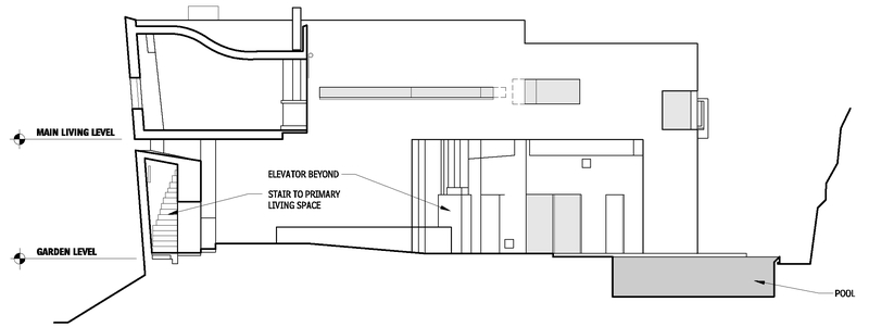
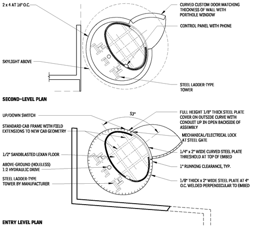
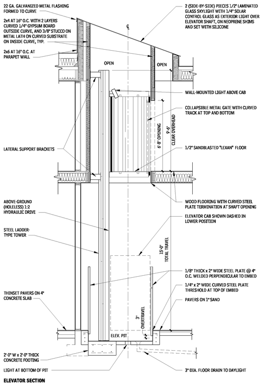
Guest quarters and gardens fill the entry level, effectively screening out the suburban world just beyond its walls. The primary living spaces are on the second level, and getting there is a matter of choice and options. A residential elevator, which passes from exterior to interior space, and a mysterious curving stair, provide passage in a manner that people with a range of abilities can use. The architecture, by Wendell Burnette, AIA, offers choice in how people move through the house, in keeping with the idea of creating multiple possibilities for living inside and outside, as well as on and above the ground plane.
ENTRY-LEVEL PLAN WITH CIRCULATION CHOICES—STAIR AND ELEVATOR
13.10
Source: Wendell Burnette Architects, Phoenix, Arizona.
SECTION SHOWING DISAPPEARING STAIR
13.11
Source: Wendell Burnette Architects, Phoenix, Arizona.
PRINCIPLE THREE: SIMPLE AND INTUITIVE USE
Use of the design is easy to understand, regardless of the user’s experience, knowledge, language skills, or current concentration level.
• Eliminate unnecessary complexity.
• Be consistent with user’s expectations and intuition.
• Accommodate a wide range of literacy and language skills.
• Arrange information consistent with its importance.
• Provide effective prompting and feedback during and after task completion.
ELEVATOR SECTION AND PLANS
13.12
Source: Wendell Burnette Architects, Phoenix, Arizona.
Source: Wendell Burnette Architects, Phoenix, Arizona.
EXAMPLE: PITTSBURGH CHILDREN’S MUSEUM
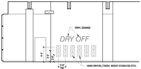
At the Pittsburgh Children’s Museum, the architect, Koning Eizenberg Architecture, and the exhibit designers, Springboard Architecture Communication Design, turned a mundane hand dryer into something more. They took an object that is simple to use and clear in its utility, multiplied it, mounted it within multiple reach ranges, and transformed it into an experience.
PRINCIPLE FOUR: PERCEPTIBLE INFORMATION
The design communicates necessary information effectively to the user, regardless of ambient conditions or the user’s sensory abilities.
• Use different modes (pictorial, verbal, tactile) for redundant presentation of essential information.
• Maximize “legibility” of essential information.
• Differentiate elements in ways that can be described (i.e., make it easier to give instructions or directions).
• Provide compatibility with a variety of techniques or devices used by people with sensory limitations.
PRINCIPLE FIVE: TOLERANCE FOR ERROR
The design minimizes hazards and the adverse consequences of accidental or unintended actions.
• Arrange elements to minimize hazards and errors: most used elements, most accessible; hazardous elements eliminated, isolated, or shielded. Make provisions for privacy, security, and safety equally available to all users.
• Provide warnings of hazards and errors.
• Provide fail-safe features.
• Discourage unconscious action in tasks that require vigilance.
PRINCIPLE SIX: LOW PHYSICAL EFFORT
The design can be used efficiently and comfortably and with a minimum of fatigue.
• Allow the user to maintain a neutral body position.
• Use reasonable operating forces.
• Minimize repetitive actions.
• Minimize sustained physical effort.
PRINCIPLE SEVEN: SIZE AND SPACE
FOR APPROACH AND USE
Appropriate size and space is provided for approach, reach, manipulation, and use regardless of user’s body size, posture, or mobility.
• Provide a clear line of sight to important elements for any seated or standing user.
• Make reach to all components comfortable for any seated or standing user.
• Accommodate variations in hand grip and size.
• Provide adequate space for the use of assistive devices or personal assistance.
EXAMPLE: ANDERSON RESIDENCE
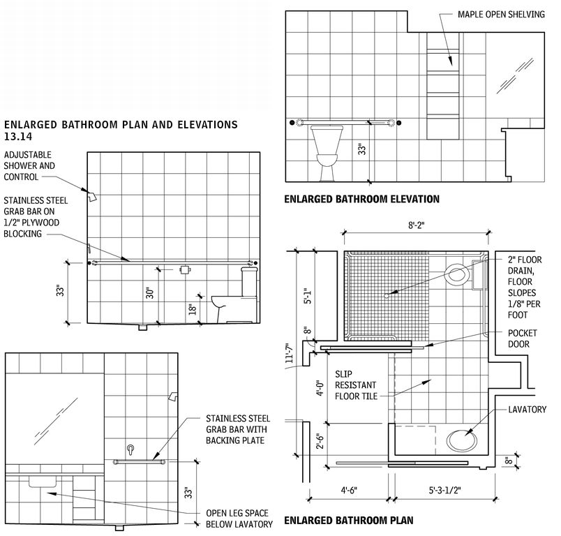
The bathroom for the Anderson Remodel in Albuquerque, New Mexico, by Geoffrey C. Adams, AIA, with Rebecca Ingram Architect and Karen J. King, RA, addresses a number of issues in a relatively small space.
Often, a second bathroom must serve visitors as well as people who reside in the house. This bath connects to an adjacent bedroom and to a hallway that is lit by daylight and leads to the public space of the house. Pocket doors, designed as a variation on the shoji screen, allow private access from the bedroom, while borrowing daylight from the hall. Alternately, the bath can be open for visitors and closed off from the bedroom. An additional division of the shower and water closet from the lavatory and grooming area offers flexibility in use for family and people who are more familiar with one another; privacy with quick proximity for people who may require some assistance; a staging area for assistive equipment; and a transitional zone for hosting groups of people.
The shower and water closet form a wet room, lined with grab bars that read as just another layer to the space. This approach is becoming more common because the design of grab bars has evolved beyond institutional utilization. They double as towel bars, while increasing safety. Open shelving was designed with visual cueing in mind, and for multiple-reach ranges (tall to small).
WATERPLAY ENVIRONMENT—WALL OF DRYERS
13.13
Source: Springboard Architecture Communication Design LLC, Pittsburgh, Pennsylvania.
The doors move easily on a caster system and are made of translucent plastic filled with blanket insulation. Being very lightweight, these doors reduce the likelihood of anyone being injured by a slamming door. Additionally, the use of sliding doors reduces the congestion associated with swinging doors; it also reduces the necessary maneuvering clearance for those using assistive devices.
ENLARGED BATHROOM PLAN AND ELEVATIONS
13.14
Source: Geoffrey C. Adams, AIA, with Rebecca Ingram Architect and Karen J. King, RA, Albuquerque, New Mexico.
ACCESSIBLE DESIGN
Accessible is a design term that was first introduced in the 1950s to describe elements of the physical environment that can be used by people with disabilities. Originally, the term described facilities that could be accessed by wheelchair users, but it has evolved to include designs for a wider group of people with more diverse functional requirements.
Society’s need for accessible design has increased as a result of continuing medical advances. Concurrent with the medical advances has been the development of new building technologies, such as residential elevators, wheelchair lifts, and power-door operators, that have made the provision of accessible facilities more practical and less expensive. Accessible design will continue to change as medical advances and building technologies continue to evolve.
From an architect’s perspective, there is a difference between appropriate accessible design for public facilities and the best approach for private, custom, accessible projects. Public accessibility standards establish general design specifications that broadly meet the targeted population’s needs. By contrast, custom accessible design should address the specific needs of an individual user.
CODES, LAWS, AND REGULATIONS
Although still an evolving field, there is already a proliferation of laws and codes governing the implementation of accessible design; therefore, architects must educate themselves, and stay current, in both the principles and the legal requirements of accessibility.
REGULATORY HISTORY OF ACCESSIBLE DESIGN
In 1961, the American National Standards Institute (ANSI) published “Accessible and Usable Buildings and Facilities,” A117.1; the first national standard for accessible design. After its initial publication, many state and local jurisdictions began to adopt ANSI A117.1 as their accessibility code, although they often modified selected standards to suit their communities. ANSI A117.1 quickly became the most widely used accessibility standard in the United States.
ANSI A117.1 is periodically revised. In 1980, it was expanded to include housing standards focused primarily on the needs of wheelchair users (specifically paraplegics). In an effort to encourage states to adopt the standards and to promote uniformity; the 1986 revision eliminated all scoping requirements.
Scoping is the extent to which a standard is applied; for example, a standard may be applied to all project elements or to only a fraction of the elements. The 1980 ANSI A117.1 standard, for instance, requires provision of a “reasonable number” of wheelchair seating spaces in places of assembly but not fewer than two spaces. After publication of the 1986 ANSI A117.1 standard, scoping was left to the discretion of the local adopting authority, which usually based it on national model codes. ANSI A117.1 includes the “technical” requirement—or “how to”—make building elements accessible.
In 1998, ANSI A117.1 was expanded to include the technical requirements for dwelling and sleeping units consistent with the requirements in the Fair Housing Act (FHA).
As ICC/ANSI A117.1 has evolved to include new information and technologies, legislation has been passed in response, including:
• Architectural Barriers Act (ABA): Passed in 1968, the ABA was the first federal legislation that required accessible design in federal facilities.
• Rehabilitation Act: Congress enacted this act in 1973 to address the absence of federal accessibility standards, as well as the lack of an enforcement mechanism. In addition, the act required facilities built with federal funds, and facilities built by entities that receive federal funds, to be accessible to persons with disabilities. Section 502 of the 1973 Rehabilitation Act created a new federal agency, the Architectural and Transportation Barriers Compliance Board (Access Board) to develop and issue minimum guidelines for design standards to be established by four standard-setting agencies.
• Uniform Federal Accessibility Standards (UFAS): In 1984, the Access Board issued the Uniform Federal Accessibility Standards (UFAS), which were established by the Department of Defense (DOD), the Department of Housing and Urban Development (HUD), the General Services Administration (GSA), and the U.S. Postal Service (USPS). UFAS is similar in format and content to the 1980 edition of A117.1.
• Fair Housing Amendments Act (FHAA): In 1988, Congress amended the Fair Housing Amendments Act (FHAA) to prohibit discriminating against individuals on the basis of disability. Although the Fair Housing Act Guidelines (FHAG) include design requirements, the FHAA is a civil rights law, not a building code. And because it is a federal law, neither state nor local building authorities can officially interpret the FHAG requirements, nor can local building inspectors enforce them. The 1988 FHAA was the first federal law to regulate private residential construction.
• Americans with Disabilities Act (ADA): In 1990, President George Herbert Walker Bush signed the ADA, a landmark piece of legislation that provided new civil rights protections for people with disabilities. Its guidelines included new federal accessibility standards and addressed the design and operation of privately owned public accommodations and state and local government facilities and programs.
• ADA Accessibility Guidelines (ADAAG): The ADAAG are very similar to the 1986 edition of ANSI A117.1 standards. ADA did not include housing design requirements because they were addressed in the earlier FHAA.
The Access Board is revising and updating its accessibility guidelines for buildings and facilities covered by the ADA of 1990 and the ABA of 1968. The final ADA/ABA Guidelines, dated July 23, 2004, will serve as the basis for the minimum standards when adopted by other federal agencies responsible for issuing enforceable standards. For the current status of this adoption process, visit the Access Board Web site (
www.access-board.gov).
RELATIONSHIP BETWEEN CIVIL RIGHTS
LAWS AND BUILDING CODES
The enactment of the 1988 FHAA and 1990 ADA created a complex relationship between federal laws and the local building codes that already existed throughout the United States. Although many of the accessible design requirements in the civil rights laws and the codes are similar, there have been considerable differences. During the last few years, however, there has been a significant effort to harmonize national model codes and ICC/ANSI A117.1 with the federal requirements.
Building codes are specific to a legal jurisdiction, such as a state, county, township, or city. These state/local regulations are usually based on national model codes developed by the International Code Council (ICC) (previously BOCA, ICBO, and SBCCI) and the National Fire Protection Association (NFPA). The state and local jurisdictions may modify the model codes and, as part of their review and enforcement process, make administrative rulings and interpretations. Over time, these modifications and interpretations make the design requirements of each municipality unique even though the underlying code is based on a national model.
Building officials use local codes to review architectural and engineering plans before they permit construction. They also perform on-site inspections to verify that the completed construction is in compliance.
Unlike municipal officials, federal agencies do not issue building permits and typically do not inspect construction. Furthermore, the federal government does not issue rulings or interpretations for individual projects. Civil rights law enforcement is a “complaintbased process” that HUD administers for fair housing and the Department of Justice (DOJ) administers for the ADA. These agencies may choose to act on a citizen complaint, or a complainant may elect to seek direct relief through federal courts. Legal decisions regarding such complaints will gradually refine unclear design and construction components of federal civil rights laws. Architects must therefore monitor federal court rulings made throughout the United States to ensure they are apprised of the most current design standard information.
As civil rights laws, the FHAA and ADA include provisions for both facility design and construction and facility operation and management. Provisions that address operation and management create new legal responsibilities that are shared between facility designers and facility operators.
This arrangement changes the traditional architect-client relationship and alters the way architects must do business. For example, architects should carefully record programming decisions, as the intended use of a new space often establishes its accessibility requirements. ADA requirements for an employee workspace, for example, are different from those for a public space. If a facility operator later changes the use of a space, compliance becomes the owner’s rather than the architect’s responsibility. Another change is that architects must now evaluate an owner’s project funding sources to determine the project’s federal accessibility requirements. This precautionary step can prevent an architect’s failure to comply with federal laws such as the 1973 Rehabilitation Act as a result of inaccurate funding information.
Terminology common to both civil rights law and building code standards can be confusing, because the same words may have different meanings. Because architects must deal with both types of standards, they should carefully review the definitions included in each.
ADA AND FHAA DESIGN REQUIREMENTS
The Americans with Disabilities Act (ADA) and the Fair Housing Amendments Act (FHAA) are the two broad federal civil rights laws that address accessible design and construction of both public and private facilities. The ADA applies to a wide range of public accommodations offered by private entities (Title III) and municipal facilities (Title II); the FHAA covers multifamily housing. Other federal laws such as the 1973 Rehabilitation Act may also apply to some projects. Architects should be aware that in many aspects federal civil rights laws are different from building codes. That means receiving a building permit does not indicate that a project design complies with these federal laws.
ADA REQUIREMENTS
The ADA includes design requirements for new facility construction, and for additions to and alterations of existing facilities that are owned, leased, or operated by both private entities and local governments. However, design standards and management responsibilities differ between the two owner groups.
Standards and responsibilities are described in the ADA, in Title III for private entities and in Title II for local governments. Title III includes design standards and scoping for general application and for certain specific building types, including transient lodging, medical care facilities, and libraries. Regulations issued by DOJ are contained in 28 CFR, Part 36.
Owners and operators of existing private facilities that serve the public have ADA construction responsibilities under what is called “barrier removal.” Local governments also have the responsibility of making all their new and existing programs accessible. Meeting this ADA responsibility for municipal programs may sometimes require new construction or physical modifications to existing facilities. The ADA also prescribes employer responsibilities for changing their policies or modifying their facilities to accommodate employees with disabilities (Title I).
Several ADA concepts determine design requirements, such as “path-of-travel” components for renovation projects and the “elevator exception” for small multistory buildings. It is imperative that architects familiarize themselves with all aspects of the law, as well as with the design standards.
Contributors:
Karen J. King, RA, University of New Mexico, Albuquerque, New Mexico; Rebecca Ingram Architect, Albuquerque, New Mexico; Kim A. Beasley, AIA, and Thomas D. Davies Jr., AIA, Paralyzed Veterans of America Architecture, Washington, DC.
ADA Title II requirements are based on the concept of “program accessibility,” which is similar to Section 504 of the 1973 Rehabilitation Act for Federal Programs. ADA requires state and local governments to provide access to all their programs for people with disabilities. Local government program responsibility includes policies and operations as well as the built environment. To provide access to existing inaccessible programs, state and local governments must develop a “transition plan” that lists the necessary changes. Inaccessible programs can be addressed either by altering policies and procedures or by modifying physical structures or by a combination of both strategies.
FHAA REQUIREMENTS
The FHAA addresses new multifamily housing constructed either by private entities or local governments. Generally, the FHAA covers projects with four or more total dwelling or sleeping units in one structure that are built for sale or lease. This includes apartments and condominiums, as well as all types of congregate living arrangements such as dormitories, boarding houses, sorority and fraternity houses, group homes, assisted-living facilities and nursing homes. Typically, townhouses are exempted because they are multistory units. Existing housing structures and remodeling, conversion, or reuse projects are not covered by FHAA. The law’s design standards include requirements for both individual dwelling units and common-use facilities such as lobbies, corridors, and parking.
The Fair Housing Accessibility Guidelines (FHAG) allow the exclusion of certain dwelling units because of site considerations such as steep topography and floodplains. The guidelines include site practicality tests for analyzing site constraints. Several major scoping issues such as multistory dwelling units and multiple ground-floor levels are discussed in the supplementary information included in the FHAG. Prior to project design, architects should carefully review this material as well as the guidelines themselves.
FEDERAL LEGISLATIVE PROCESS
To help understand current civil rights law design requirements and monitor the publication of new standards, architects should become familiar with the federal legislative process. Information on federal design standards is available within specific acts, in the resultant regulations, and in published guidelines. Additional information is available in the legislative history of an act and in the numerous documents issued during the “rule-making process.”
The administrative process for implementing federal laws requires public notice (in the Federal Register) and a public comment period for any proposed new regulations or guidelines. Architects should monitor this ongoing process to track the new standards that are periodically added to the existing accessibility guidelines and to verify their adoption status. The architectural guidelines for laws such as the ADA are also periodically revised through the same rule-making process.
Technical assistance manuals (TAMs) are another design information source. Administering agencies such as the DOJ and HUD periodically publish these manuals to clarify existing guidelines or standards.
APPLICABLE FEDERAL STANDARDS
FOR SPECIFIC PROJECTS
The first step in evaluating the accessibility requirements for a specific project is to determine which laws and regulations apply. Project accessibility requirements may be determined by answering the following questions:
• What type of building or structure will be built?
• Who owns the facility?
• Where will the construction funds originate?
• What other federal funding will the project’s owner receive?
• Who are the intended users of a space or component?
Table 13.15 lists the applicable standards for many types of projects.
APPLICABLE ACCESSIBILITY STANDARDS FOR SAMPLE PROJECTS
13.15
| PROJECT DESCRIPTION | FEDERAL LAWS | BUILDING CODES |
|---|
| Federally owned project of any type | 1968 Architectural Barriers Act 1973 Rehabilitation Act Other standards as described by the agency | State and/or local building codes may apply. |
| Project that utilizes federal funds or is built by the recipient of federal funds (private or government) | 1968 Architectural Barriers Act 1973 Rehabilitation Act, UFAS Other standards appropriate with ownership use and type | State and/or local building codes may apply. |
| Local government-owned commercial or public facility | ADA Title II 1973 Rehabilitation Act | State and/or local building codes may apply. |
| Local government-owned multifamily housing | ADA Title II 1973 Rehabilitation Act 1988 Fair Housing Amendments Act | State and/or local building codes may apply. |
| Privately owned public accommodation or commercial facility | ADA Title III | State and/or local building codes may apply. |
| Privately owned multifamily housing | 1988 Fair Housing Amendments Act (Public accommodation spaces must meet ADA.) | State and/or local building codes may apply. |
| Privately leased, government-owned public accommodation | ADA Title III-Tenant ADA Title II-Owner | State and/or local building codes may apply. |
| Government-leased, privately owned public accommodation ADA | 1973 Rehabilitation Act-Tenant ADA Title II-Tenant Title III-Owner | State and/or local building codes may apply. |
| Church-operated, church-owned facility | None | State and/or local building codes may apply. |
| Privately operated, church-owned facility | ADA Title III-Tenant None-Owner | State and/or local building codes may apply. |
| Church-operated, privately owned facility | None-Tenant ADA Title III-Owner | State and/or local building codes may apply. |
FEDERAL RULE-MAKING PROCESS
13.16
The technical material covered in the discussions here is drawn from the minimum legal standards required to make buildings, sites, and their constituent parts accessible. Note that these are “minimums” based on a calculated percentage of the population and, as such, are still quite challenging for many individuals. For many reasons, including deviations in finish material dimensions and construction errors, architects should consider exceeding the minimums and would be well advised to gain an understanding of how people with disabilities use spaces.
NOTES
13.15 Temporary facilities must meet the same federal standards as similar permanent facilities.
State and local building codes may apply for all types of projects.
Contributors:
Kim A. Beasley, AIA, and Thomas D. Davies Jr., AIA, Paralyzed Veterans of America Architecture, Washington, DC.
BUILDING BLOCKS
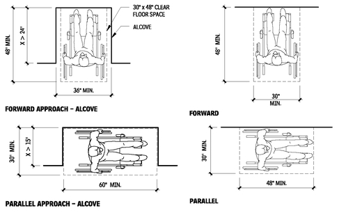
MANEUVERING CLEARANCES
13.17
MANEUVERING CLEARANCES
13.18
WHEELCHAIR TURNING SPACE
13.19
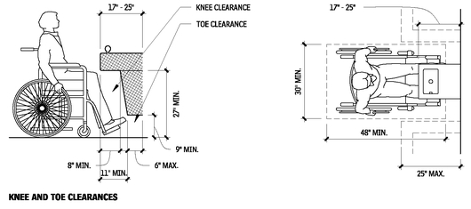
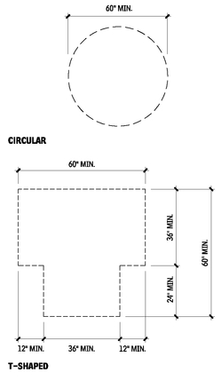
Knee and toe clearance that is included as part of a T-shaped turning space is allowed only at either the base of the T or on one arm of the T. In some configurations, the obstruction of part of the T-shape may make it impossible for a wheelchair user to maneuver to the desired location. Floor surfaces of a turning space must have a slope that is not steeper than 1:48.
NOTES
13.17 a. Floor surfaces of a clear floor space must have a slope not steeper than 1:48.
b. One full, unobstructed side of the clear floor space must adjoin or overlap an accessible route or adjoin another clear floor space.
Contributors:
Kim A. Beasley, AIA, and Thomas D. Davies Jr., AIA, Paralyzed Veterans of America Architecture, Washington, DC.
REACH RANGES FOR ACCESSIBILITY
PARALLEL/SIDE REACH LIMITS
13.20
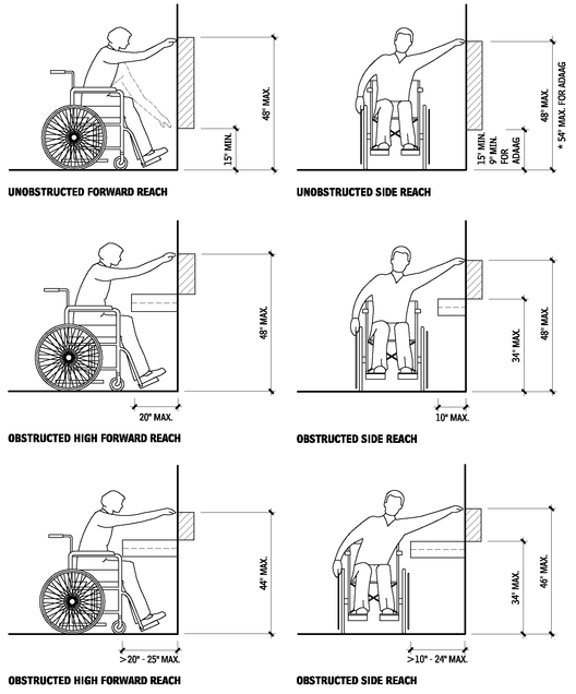
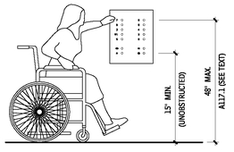
ICC/ANSI A117.1 requires the unobstructed side reach to be 15 in. minimum to 48 in. maximum, with these exceptions:
1. ICC/ANSI A117.1 provides exception for existing elements located 54 in. maximum above the floor or ground.
2. ICC/ANSI A117.1 provides exception for elevator car controls, allowing buttons at 54 in. maximum, with a parallel approach, where the elevator serves more than 16 openings. This exception may be revisited in future editions, when the elevator industry has had an opportunity to develop alternate control configurations.
3. ICC/ANSI A117.1 does not apply the 48-in. restriction to tactile signs. Tactile signs must be installed so the tactile characters are between 48 and 60 in. above the floor. Below this height, tactile characters are difficult to read by standing persons, as the hand must be bent awkwardly or turned over (similar to reading upside down) to read the message.
REACH RANGES
13.21
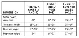
CHILDREN’S REACH RANGES FROM A WHEELCHAIR (IN.)
13.22
Contributor:
Lawrence G. Perry, AIA, Silver Spring, Maryland.
OPERABLE PARTS
Accessible controls and operating mechanisms should be operable with one hand and not require tight grasping, pinching, or twisting of the wrist. Operating force must not exceed 5 lb.
PROTRUDING OBJECTS IN CIRCULATION PATHS
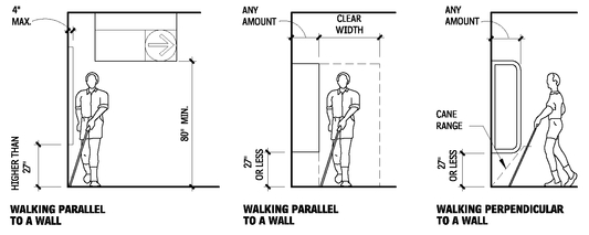
FREESTANDING OBJECTS
13.23
REDUCED VERTICAL CLEARANCE
13.24
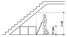
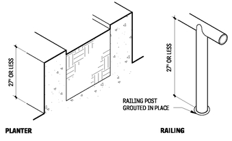
OVERHEAD HAZARD PROTECTION—EXAMPLES
13.25
DIMENSIONS OF PROTRUDING OBJECTS
13.26
NOTES
13.24 a. Protection from overhead hazards can be provided by built-in elements such as planters or railings, or curbs.
b. Designers can reduce or eliminate most overhead hazards (e.g., low-headroom hazards can be avoided by enclosing areas under stairs and escalators).
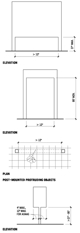
13.26 a. Wall sconces, fire extinguisher cabinets, drinking fountains, signs, and suspended lighting fixtures are examples of protruding objects.
b. Some standards allow doorstops and door closers 78 in. minimum above the floor.
c. Protruding objects are not permitted to reduce the required width of an accessible route.
Contributor:
Lawrence G. Perry, AIA, Silver Spring, Maryland.
ACCESSIBLE ROUTES AND WALKING SURFACES
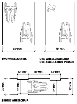
CLEAR WIDTH OF AN ACCESSIBLE ROUTE
13.27
CHANGES IN LEVEL
13.28
FLOOR AND GROUND SURFACES
13.29
CLEAR WIDTH AT TURNS
13.30
Source: ICC/ANSI A117.1.
NOTES
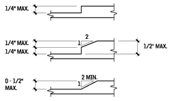
13.27 Clear width of the accessible route must be 36 in.; however, it may be reduced to 32 in. for a distance of 24 in., as shown. 13.28 a. Changes in level greater than 1/2 in. must be ramped.
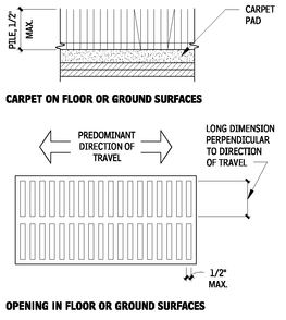
b. Some standards prohibit changes in level in clear floor space, maneuvering clearances, wheelchair turning space, and access aisles. 13.29 a. All surfaces must be firm, stable, and slip-resistant.
b. Carpets must be securely attached with a firm pad, or no pad, and a level loop, textured loop, level cut pile, or level cut/uncut pile texture.
c. Other openings, such as in-wood decking or ornamental gratings, must be designed so that a 1/2-in.-diameter sphere cannot pass through the opening. The potential for wood shrinkage should be considered.
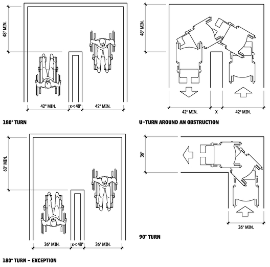
13.30 If x is less than 48 in., the route must be 42 in. minimum, except where the clear width at the turn is 60 in. minimum.
Contributor:
Lawrence G. Perry, AIA, Silver Spring, Maryland.
REQUIREMENTS FOR ACCESSIBLE ROUTES
Accessible routes are generally required as follows:
• Site arrival points: From each type of site arrival point (public transportation stops, accessible parking spaces, passenger loading zones, and public streets or sidewalks) to an accessible entrance. Consult the applicable regulation to determine the required number of accessible entrances. Building codes generally require that at least 50 percent of the public entrances, but no less than one, be accessible. Under the Fair Housing Accessibility Guidelines (FHAG), site conditions may allow some buildings to be exempt from this requirement.
• Within a site: Between accessible buildings, facilities, elements, and spaces on the site.
• Intent: The intent of this requirement is not to require accessible routes where no “connection” is otherwise intended between buildings or facilities, but to ensure that where a connection is intended an accessible connection is also provided.
• FHAG vehicular route exception: FHAG allows a vehicular route to be provided in lieu of an accessible route between covered dwelling units and public and common-use site facilities where the slope of the site or other restrictions prevents the use of an accessible route. Accessible parking spaces are required at the covered dwelling units and at the facilities served only by the vehicular route.
• Building code vehicular route exception: Model building codes also allow the use of a vehicular route in lieu of an accessible route where the only means of access between two accessible facilities is “a vehicular way, not intended for pedestrian access.” This exception is not limited to slope or other site restrictions.
• Multilevel buildings and facilities: Between all levels, including mezzanines, in multistory buildings, unless exempted.
• ADA elevator exception: Buildings with only two floors are exempt from providing an accessible route to the upper or lower level. Buildings with less than 3000 sq ft per floor, regardless of height, are exempt from providing an accessible route to upper or lower floor levels. Neither exception applies to shopping centers, offices of professional health care providers, public transportation terminals, or state and local government facilities.
• Building code elevator exception: Model building codes generally exempt a maximum aggregate area of 3000 sq ft, regardless of the number of levels. Similar to the ADA restrictions, this exception cannot be used in offices of health care providers, passenger transportation facilities, or mercantile occupancies with multiple tenants. Consult the applicable local code.
• FHAG elevator requirements: Model code and FHAG elevator requirements for buildings containing dwelling units, and not public or common-use spaces. The presence of an elevator determines the extent of units covered (and the floors required to be served by an accessible route). When elevators are provided, they generally must serve all floors; an exception is provided for elevators serving only as a means of access from a garage to the lowest floor with dwelling units. When elevators are not provided, only the “ground floor” units are subject to the FHAG and model code Type B requirements. In mixed-use construction, an accessible route is required to the first level containing dwelling units, regardless of its location. Consult FHAG and model codes for specific requirements.
• Levels not containing accessible elements or spaces: For facilities in which only a percentage of the spaces provided are required to be accessible (assembly, residential, institutional, and storage), the model codes do not require an accessible route to serve levels not containing required accessible spaces. For example, a motel would not require an accessible route to upper floors if all required accessible units or rooms and common areas were located on the accessible level. Separate requirements for dispersion of accessible elements and spaces may still require multiple accessible levels. Consult the applicable local code.
• Accessible spaces and elements: To all spaces and elements that are required to be accessible.
• Toilet rooms and bathrooms: ADA and the model codes generally require that all toilet and bathing rooms be accessible. This does not trigger a requirement for accessible routes if the floor level is not otherwise required to have an accessible route.
• Alterations: The ADA and the model building codes generally do not require that altered elements trigger a requirement for accessible routes to the elements, unless covered under specific “primary function” requirements. In alterations involving “primary function” areas, the accessible route obligation is triggered but is subject to specific limitations. Consult the ADA and the applicable local code.
COMPONENTS OF ACCESSIBLE ROUTES
Accessible routes are permitted to include the following elements:
• Walking surfaces with a slope of less than 1:20
• Curb ramps
• Ramps
• Elevators
• Platform (wheelchair) lifts (The use of lifts in new construction is limited to locations where they are specifically permitted by the applicable regulations. Lifts are generally permitted to be used as part of an accessible route in alterations.)
Each component has specific technical criteria that must be applied for use as part of an accessible route. Consult the applicable code or regulation.
LOCATION OF ACCESSIBLE ROUTES
Accessible routes should be located as follows:
• Interior routes: Where an accessible route is required between floor levels, and the general circulation path between levels is an interior route, the accessible route must also be an interior route.
• Relation to circulation paths: Accessible routes must “coincide with, or be located in, the same area as a general circulation path.” Avoid making the accessible route a “second-class” means of circulation. Consult the applicable regulations for additional specific requirements regarding location of accessible routes.
• Directional signs: Where the accessible route departs from the general circulation path and is not easily identified, directional signs should be provided as necessary to indicate the accessible route. The signs should be located so that a person does not need to backtrack.
CURBS AND PARKING
Follow these design guidelines for accessible curb ramps and passenger loading.
• Design storm drainage utilities to shed water away from curb ramps.
• The dimensions shown in Figures 13.31 to 13.33 are for new construction. For alterations when these dimensions are impractical, refer to guidelines and standards.
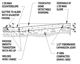
• Refer to applicable codes, standards, and regulations for detectable warning requirements and locations.
ACCESSIBLE CURB RAMP PLAN
13.31
CURB RAMP SECTION
13.32
Contributor:
Lawrence G. Perry, AIA, Silver Spring, Maryland.
CURB RAMP TYPES
13.33
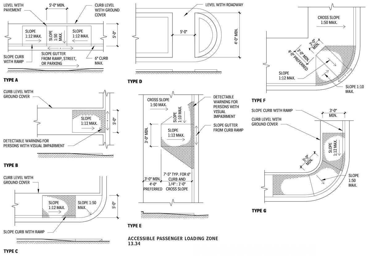
PASSENGER LOADING ZONES
Where passenger loading zones are provided, at least one accessible parking loading zone must be provided. An accessible parking loading zone is also required where there is valet parking.
Accessible passenger loading zones must have a 96-in.-wide, minimum, by 20-ft-long vehicle pull-up space, with an adjacent access aisle that is 60 in. wide and as long as the vehicle pull-up space. The access aisle must be marked, at the same level as the vehicle pull-up space, and adjoin an accessible route.
The vehicle pull-up space and access aisle must be level, with slopes no steeper than 1:48. The accessible parking loading zone and the vehicular route to the entrance and exit serving it must have a vertical clearance of 114 in. minimum.
ACCESSIBLE PASSENGER LOADING ZONE
13.34
NOTES
13.33 For types E and F, in alterations where there is no landing at the top of curb ramps, curb ramp side flares must not be steeper than 1:12.
Contributors:
Mary S. Smith, PE Walker Parking Consultants/Engineers, Inc., Indianapolis, Indiana; Mark J. Mazz, AIA, PA, Hyattsville, Maryland.
ACCESSIBLE PARKING
The information provided here conforms to the Americans with Disabilities Act Accessibility Guidelines for Buildings and Facilities (36 CFR 1191; July 26, 1991), also known as ADAAG, and Bulletin #6: Parking (August 2003), both issued by the Architectural and Transportation Barriers Compliance Board, and ICC/ANSI A117.1, 2003. State and local requirements may differ and the requirements providing the greater access apply.
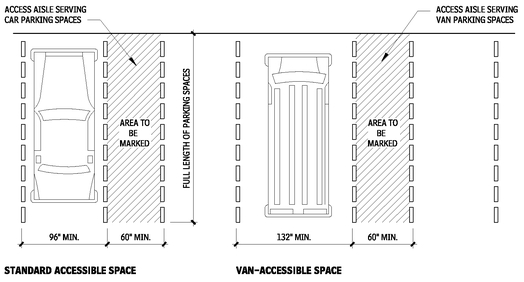
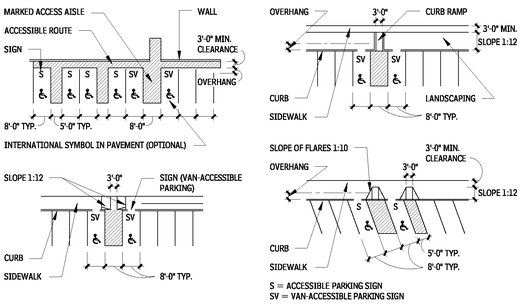
• Accessible parking stalls should be 8 ft wide with an adjacent 5ft access aisle.
• Van-accessible stalls should be 11 ft wide with an adjacent 5-ft access aisle; or they are permitted to be 8 ft wide with an adjacent 8 ft access aisle. The access aisle must be accessible from the passenger side of the vehicle. Backing into 90º stalls from a two-way aisle is an acceptable method of achieving this; but with angled parking, the aisle must be on the right side. Vehicular clearance at the van-accessible stall, adjacent access aisle, and along the path of travel to and from a van-accessible stall should be 8 ft-2 in. In parking structures, van-accessible stalls may be grouped on a single level.
• Access aisles must be clearly marked and be the same length as the adjacent parking space. They also must be at the same level as parking stalls (not above, at sidewalk height). Required curb ramps cannot be located in access aisles.
• Parking spaces and access aisles should be level with surface slopes, not exceeding 1:50 (2 percent) in any direction.
• The stalls required for a specific facility may be relocated to another location if equivalent or greater accessibility in terms of distance, cost, and convenience is ensured.
• Accessible stalls in the numbers shown in Table 13.35 must be included in all parking facilities.
• The access aisle must join an accessible route to the accessible entrance. It is recommended that accessible routes be configured to minimize wheelchair travel behind parked vehicles.
• Signs with the International Symbol of Accessibility are required for accessible spaces, unless there are four or fewer total spaces provided. Signs must be mounted 60 in. minimum from the ground surface to the bottom of the sign.
• Accessible parking spaces must be on the shortest accessible route to the accessible building entrance. If there is more than one accessible entrance with adjacent parking, accessible parking must be dispersed and located near the accessible entrances.
• The accessible parking spaces must be located on the shortest route to an accessible pedestrian entrance in parking facilities that do not serve a particular building.
• When different types of parking are provided—for example, surface, carport, and garage spaces—the accessible parking spaces must be dispersed among the various types.
REQUIRED MINIMUM NUMBER OF ACCESSIBLE PARKING SPACES
13.35
| TOTAL SPACES PROVIDED | REQUIRED MINIMUM NUMBER OF ACCESSIBLE SPACESa |
|---|
| 1 to 25 | 1 |
| 26 to 50 | 2 |
| 51 to 75 | 3 |
| 76 to 100 | 4 |
| 101 to 150 | 5 |
| 151 to 200 | 6 |
| 201 to 300 | 7 |
| 301 to 400 | 8 |
| 401 to 500 | 9 |
| 501 to 1000 | 2% of total |
| More than 1000 | 20, plus one for each 100 over 1000 |
PARKING SPACE AND ACCESS AISLE LAYOUT
13.36
ACCESSIBLE PARKING LAYOUTS
13.37
Following are exceptions to the requirements outlined in Table 13.98:
• At facilities providing outpatient medical care and other services, 10 percent of the parking spaces serving visitors and patients must be accessible.
• At facilities specializing in treatment or services for persons with mobility impairments, 20 percent of the spaces provided for visitors and patients must be accessible.
• The information in Table 13.35 does not apply to valet parking facilities, but such facilities must have an accessible loading zone. One or more self-park, van-accessible stalls are recommended for patrons with specially-equipped driving controls.
• The requirements for residential facilities differ slightly among applicable codes and guidelines, but generally 2 percent of the parking is required to be accessible. This parking must be dispersed among the various types of parking, including surface, covered carports, and detached garages.
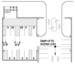
ACCESSIBLE PARKING IN DEDICATED BAY
13.38
NOTES
13.35 a. For every six or fraction of six required accessible spaces, at least one must be a van-accessible parking space
Contributors
Mary S. Smith, PE, Walker Parking Consultants/Engineers, Inc., Indianapolis, Indiana; Mark J. Mazz, AIA, PA, Hyattsville, Maryland.
ACCESSIBLE RAMPS
RAMPS
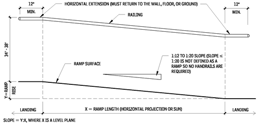
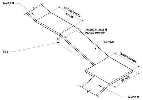
• Accessible ramps must have running slopes of 1:12 or less; surfaces with a running slope greater than 1:20 are considered ramps. All design parameters shown on Figure 13.39 are based on ICC/ANSI A117.1. Provide ramps with the least possible running slope. Wherever possible, accompany ramps with stairs for use by those individuals for whom distance presents a greater barrier than steps.
• Design outdoor ramps and approaches so water will not accumulate on the surface. Maximum cross slope is 1:48.
• Landings should be level at top and bottom of ramp run and at least as wide as the run leading to it. A 60 by 60 in. landing is required where ramp changes direction. Provide level maneuvering clearances for doors adjacent to landings. If doors are subject to locking, landings must be sized to provide a wheelchair turning space.
• Handrails are required on both sides when rise is greater than 6 in.
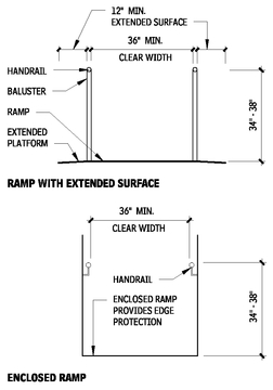
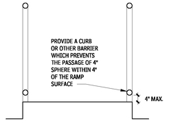
• Edge protection is required at ramps and landings. Refer to local building codes for guard requirements.
COMPONENTS OF A RAMP
13.39
HANDRAIL DESIGN
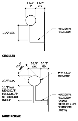
13.40
RAMP SECTIONS
13.41
Dimensions are based on ICC/ANSI A117.1. Provide continuous handrails at both sides of ramps and stairs and at the inside handrail of switchback or dogleg ramps and stairs. If handrails are not continuous at bottom, top, or landings, provide handrail extensions as shown in the ramp example in Figure 13.39; ends of handrails must be rounded or returned smoothly to floor, wall, or post. Provide handrails of size and configuration shown and gripping surfaces uninterrupted by newel posts or other construction elements; handrails must not rotate within their fittings. The handrails and adjacent surfaces must be free from sharp or abrasive elements.
CURB OR BARRIER
13.42
Contributor:
Lawrence G. Perry, AIA, Silver Spring, Maryland.
RAMP LANDINGS
13.43
RAMP EDGE PROTECTION DETAILS
13.44
ELEVATORS
Model codes may allow or require elevators to serve as a means of egress in some circumstances when standby power is provided.
ELEVATOR LOBBY
13.45
NOTE
13.43 Required handrails and ramp edge protection are not shown in this drawing. Building codes require a guard when the drop-off adjacent to any walking surface is greater than 30 in. This would include ramps, stairs, and landings.
Contributor:
Lawrence G. Perry, AIA, Silver Spring, Maryland.
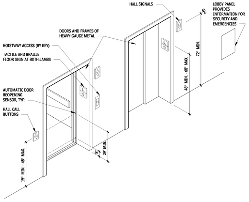
Elevator doors must open and close automatically and have a reopening device that will stop and reopen the car and hoistway door if the door is obstructed. Although the device cannot require contact to activate, contact can occur before the door reverses direction.The device must remain effective for at least 20 seconds.
Tactile designations at each jamb of hoistway doors should be 2 in. high, a maximum of 60 in. above the floor. A five-pointed star should be included at the main entry level.
Hall call buttons should be raised or flush, 15 to 48 in. unobstructed above the floor measured to the center line of the highest operable part, with the up button located above the down button.
Audible hall signals should sound once for cars traveling in the up direction and twice for cars traveling down. Check the applicable regulations for required decibel level and frequency of audible signals. In-car signals are permitted in lieu of hall signals, as long as they meet all the requirements for visibility and timing.
DESTINATION-ORIENTED ELEVATOR SYSTEMS
Destination-oriented elevator systems assign passengers to specific cars by requiring them to enter their destination floor at a keypad or by other means, such as use of a coded identification card. ICC/ANSI A117.1 provides detailed accessibility criteria for this type of elevator system.
Destination-oriented elevator systems must provide both an audible and a visible signal to indicate the responding car. The audible signal is activated by pressing a tactile button identified by the International Symbol for Accessibility. The tactile button must be located immediately below the keypad or floor buttons. A visible display is required in the car to identify the registered destinations for each trip, and an automatic verbal announcement is required to announce the floor as the car stops.Tactile signs at hoistway jambs are required to identify not only the floor level but also each car.
ICC/ANSI A117.1 allows use of a telephone-style keypad in lieu of buttons for each floor. Keypads used for destination floor input must have a telephone keypad arrangement, with a tactile dot on the number-5 key.
ELEVATOR EMERGENCY COMMUNICATIONS
Elevator cars must provide an emergency two-way communication system between the car and a point outside the hoistway. Controls must be located within accessible reach ranges. When the system includes a handset, the cord must be at least 29 in. long. The system must provide both audible and visible signals; it cannot be limited to voice communication.
ELEVATOR CAR POSITION INDICATORS
Within elevator cars, audible and visible signals are required to identify the location of the car. Visible signals at least 1/2-in. high must be provided for each floor the car serves; these signals must illuminate to indicate the floors at which the car stops or passes.
Audible signals for new elevators must be automatic verbal announcements that indicate the floor at each stop. Exceptions allow the use of audible signals for some low-rise hydraulic elevators.
ELEVATOR CAR CONTROL PANELS
ICC/ANSI A117.1 requires all elevator car controls to be 15 in. minimum and 48 in. maximum above the floor. An exception is provided for elevator cars serving 16 or more openings, where a parallel approach is provided. Controls as high as 54 in. are allowed. When car control buttons are higher than 48 in. sequential step scanning must be provided. Existing elevators allow controls at 54 in. with a parallel approach until the panel is changed out. Buttons must be at least 3/4 in. in diameter and can be raised or flush. Existing recessed buttons are generally permitted to remain. Buttons for floor designations should be located in ascending order. Visual characters, tactile characters, and Braille are required to identify buttons. Tactile characters and Braille should be to the immediate left of each button.
CONTROL PANEL HEIGHT
13.46
ASME A17.1, “Safety Code for Elevators and Escalators,” applies to all elevators and escalators and covers general elevator safety and operational requirements. It has been adopted in virtually all jurisdictions. All sizes shown in this discussion are based on ICC/ANSI A117.1, which contains extensive accessibility provisions for passenger elevators, destination-oriented elevator systems, limiteduse /limited-application elevators, and private residence elevators. The ASME A18.1, “Safety Standard for Platform Lifts and Stairway Chairlifts,” applies to all lifts, along with other applicable codes and standards. Consult the applicable accessibility regulations for elevator, escalator, and lifts for exceptions and requirements.
Contributor:
Lawrence G. Perry, AIA, Silver Spring, Maryland.
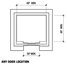
INSIDE DIMENSIONS OF ACCESSIBLE ELEVATOR CARS
13.47
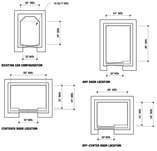
A 5/8-in. tolerance is permitted at 36-in. elevator doors, allowing the use of standard 35-3/8 in. clear-width doors. Any other car configuration that provides a 36-in. door and either a 60-in. diameter or T-shaped wheelchair turning space within the car, with the door in the closed position, is permitted. Inside car dimensions are intended to allow an individual in a wheelchair to enter the car, access the controls, and exit.
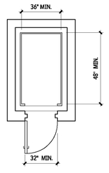
PRIVATE RESIDENCE ELEVATOR
13.48
This type of elevator is permitted as part of an accessible route within dwelling units. Car size shown is per ICC/ANSI A117.1. Verify the car size requirements of applicable accessibility regulations. Controls are located in a side wall 12 in. minimum from an adjacent wall. Doors must be located on the narrow end of the car. Car door/gates are required to be power-operated. Cars with openings on only one end require a person in a wheelchair to either enter or exit by moving backward; therefore, in a single-opening configuration, the hoistway doors/gate must be low-energy, power-operated doors. Cars with openings on each end allow a wheelchair user to roll through (enter and exit in a forward direction); manual, self-closing hoistway doors/gates are permitted. A telephone with a cord length of 29 in. and signal device are required in the car.
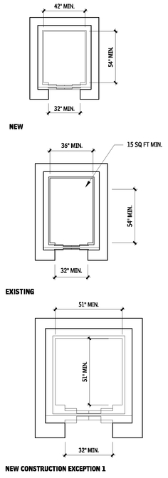
LIMITED-USE/LIMITED-APPLICATION ELEVATOR
13.49
Limited-use/limited-application (LULA) elevators are permitted to be used as part of an accessible route in certain conditions. Check applicable accessibility regulations for permitted installations. LULAs must comply with ASME A17.1. LULA elevators have a smaller car size, requiring a person in a wheelchair to either enter or exit by moving backward, unless the car has openings on each end. Car size and vertical travel is limited by ASME A17.1. Because LULAs move more slowly than other passenger elevators, they may not be appropriate when large numbers of people must be served. Car controls are centered on a side wall. Low-energy, power-operated swing doors are permitted at the hoistway entrance, provided they remain open for 20 seconds when activated. See ICC/ANSI A117.1 for emergency communication, signage, control and signal requirements.
WHEELCHAIR LIFTS
VERTICAL WHEELCHAIR LIFTS
Vertical wheelchair (platform) lifts are generally permitted to be used as part of an accessible route in new construction only to reach limited access or small spaces, such as:
• Performing areas in assembly occupancies
• Wheelchair spaces in assembly occupancies
• Seating spaces in outdoor dining with A5 occupancy (bleachers, grandstands, stadiums, ect.)
• Courtrooms
• Spaces not open to the public with an occupant load of no more than five spaces within a dwelling unit
In some regulations, wheelchair lifts are permitted where site constraints prevent the use of ramps or elevators.
VERTICAL WHEELCHAIR LIFTS
13.50
When vertical wheelchair lifts are used in new construction, an accessible means of egress may be required from the spaces served by the lifts. These lifts are not permitted to be used as part of an accessible means of egress except where allowed as part of an accessible route by model codes. In such circumstances, standby power is required.
Vertical Wheelchair lifts are generally permitted as part of an accessible route in alterations to existing buildings.
Vertical Wheelchair lifts that are part of an accessible route are required to comply with ASME A18.1 and must provide a wheelchair-sized clear floor space, level floor surfaces, and accessible operable parts. These lifts are not permitted to be attendantoperated; they must allow for unassisted entry and exit.
ICC/ANSI A117.1 allows self-closing manual doors or gates on lifts with doors or gates on opposite sides (a roll-through configuration). Other lifts must have low-energy, power-operated doors or gates that remain open for at least 20 seconds. Doors/gates located on the ends of lifts must provide 32 in. clear width; doors/gates located on the side of a lift must provide 42 in. clear width.
Contributor:
Lawrence G. Perry, AIA, Silver Spring, Maryland.
GENERAL
Not all lifts comply with ADAAG and ICC/ANSI A117.1 requirements. Verify applicable regulations before selecting a specific type of lift. Consult ASME 18.1, “Safety Standard for Platform Lifts and Stairway Chairlifts.”
Wheelchair lifts are suitable for retrofits of buildings that are not barrier-free. Bridges are available from manufacturers for installation over stairs. Recommended speed is 10 to 19 fpm. Capacity should be 500 to 750 lb.
Lifts operate on standard household current and are suitable for interior or exterior applications.
VERTICAL WHEELCHAIR LIFT REQUIREMENTS
13.51
| TYPICAL | PRIVATE RESIDENCE |
|---|
| 42” high door for top and bottom landings; mechanical/ electrical interlock, solid construction | 36” high door for top landing; bottom landing can have guard (other requirements similar to 42” high door) |
| Platform sides: 42” high, solid construction | Platform sides 36” high, solid construction |
| Grab rails | Same |
| Enclosure or telescoping toe guard | Obstruction switch on platform |
| Maximum travel 12’ | Maximum travel 10’ |
| Automatic guard 6” at bottom landing in lieu of door |
| Push button operation for rider | Push button operation for rider |
WHEELCHAIR LIFTS
13.52
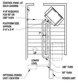
Inclined wheelchair lifts can be adapted to straight-run and spiral stairs. Standard types run along guide rails or tubes fastened to solid wall, stairs, or floor structure. Power units may be placed at the top or bottom of the lift run or in the lift chassis, depending on the manufacturer. Some inclined lift systems fold up out of the way for daily stair use.
Recommended speed is 20 to 25 fpm on straight runs, 10 fpm on curved sections. Capacity should be 500 lb. The typical platform size is 30 by 40 in. Check local code capacities. A chairlift cannot serve as part of a required accessible route.
INCLINED WHEELCHAIR LIFT REQUIREMENTS
13.53
| TYPICAL RESIDENCE | PRIVATE |
|---|
| 42” high self-closing door: solid construction, mechanical/ electrical interlock, lower landing | 36” high self-closing door: solid construction, mechanical/ electrical interlock, upper landing |
| 42” platform side guard: not used as exit; solid construction | 36” platform side guard: not used as exit; solid construction |
| 6” guard: permitted in lieu of side guard | 6” guard: permitted in lieu of side guard |
| 6” retractable guard: to prevent wheelchair rolling off platform | 6” retractable guard: to prevent wheelchair rolling off platform |
| Door required at bottom landing | Underside obstruction switch bottom landing |
| Travel three floors maximum | Travel three floors maximum |
| Push button operation by rider | Push button operation by rider |
Contributor:
Eric K. Beach, Rippeteau Architects, PC, Washington DC.
INCLINED WHEELCHAIR LIFT
13.54
INCLINED WHEELCHAIR LIFT PLAN WITH TURNS
13.55
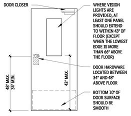
ACCESSIBLE DOORS
ACCESSIBLE DOOR FEATURES
13.56
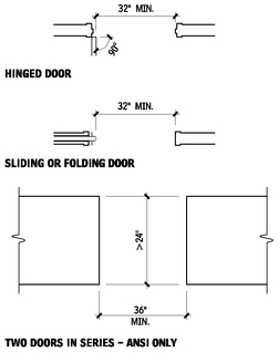
CLEAR WIDTH OF ACCESSIBLE DOORWAYS
13.57
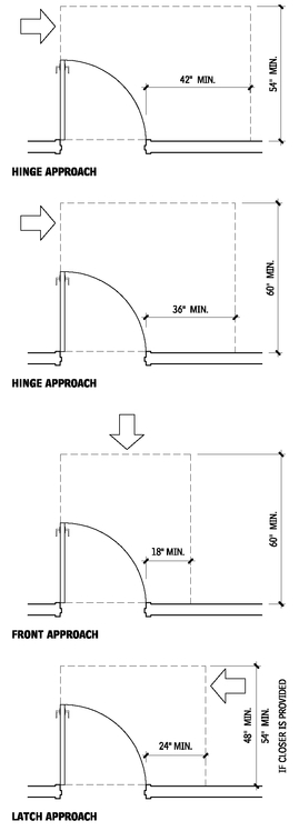
PULL-SIDE MANEUVERING CLEARANCE AT SWINGING DOORS
13.58
NOTES
13.56 a. Door Hardware: Specify hardware that can be operated with one hand, without tight grasping, pinching, or twisting of the wrist.
b. Thresholds: Thresholds are typically limited to 1/2 in. maximum height; however, some standards allow a 3/4-in. height beveled at a 1:2 maximum slope for existing or altered thresholds and patio sliding doors in some dwelling units.
c. Opening force: Interior doors (other than fire doors) should be able to be operated with 5 lb of force. Exterior doors and fire doors may be regulated by the authority having jurisdiction.
d. Door closers must be adjusted so that there is at least a five-second interval from the time the door moves from 90º to 12º open.
Contributors:
Eric K. Beach, Rippeteau Architects, PC, Washington, DC; Lawrence G. Perry, AIA, Silver Spring, Maryland.
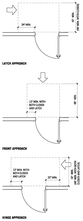
PUSH-SIDE MANEUVERING CLEARANCE AT SWINGING DOORS
13.59
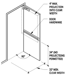
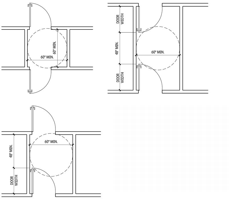
For a hinged door, the clear width is measured between the face of the door and the door stop with the door open at a 90° angle. For a sliding or folding door, the clear width is measured between the edge of the door and the jamb with the door fully open. Hardware must be accessible with the door in fully open position. Openings and doors without doorways more than 24 in. in depth must have a clear width of 36 in. minimum. Doors in dwelling units covered by FHAG are permitted to have a “nominal” 32-in. clear width. HUD allows a 2 ft-10 in. with 31-5/8-in. clear width swing door to satisfy this requirement. ICC/ANSI A117.1 allows a 31-3/4-in. clear width.
PROJECTIONS INTO CLEAR WIDTH
13.60
TWO DOORS IN SERIES—ICC/ANSI A117.1 ONLY
13.61
Source: ICC/ANSI A117.1.
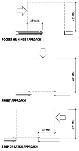
Manual doors and doorways and manual gates on accessible routes must comply. With double-leaf doors and gates, at least one of the active leaves must comply. Maneuvering clearances include the full width of the door. Maneuvering clearances are also required at power-assisted doors. Maneuvering clearances are not applicable at full-powered automatic doors or low-energy power-operated doors. The floor and ground surface within the required maneuvering clearance of a door must not slope more than 1:48, and must be stable, firm, and slip-resistant. Where any obstruction within 18 in. of the latch side of a doorway projects more than 8 in. beyond the face of the door (e.g., a recessed door) maneuvering clearances for a forward approach must be provided. Maneuvering clearances are required only on the exterior side of the primary entry door of dwelling units covered by the Fair Housing Accessibility Guidelines
(FHAG).
NOTES
13.60 Exceptions
a. Door closers and door stops are permitted 78 in. above the floor. b. For alterations, a 5/8-in. maximum projection is permitted for the latch-side stop.
Contributor:
Lawrence G. Perry, AIA, Silver Spring, Maryland.
MANEUVERING CLEARANCE AT SLIDING AND FOLDING DOORS
13.62
ACCESSIBLE COMMUNICATIONS FEATURES
TACTILE SIGNS
Tactile signage with raised characters and Braille are required on signs provided as permanent designations of rooms and spaces. ICC/ANSI A117.1 allows either combined tactile/visual characters or separate tactile characters with redundant visual characters. By providing duplicate characters, the tactile characters can be made easier to read by touch, and a wider variety of visual characters can be used. Room numbers, room names, exit stairs, and restrooms are examples of spaces with “permanent” designations. Tactile characters must be located between 48 and 60 in. above the floor or ground.
Tactile signs at doors must be located so that a person reading the sign will not be hit by a door that is being opened. ICC/ANSI A117.1 allows door-mounted tactile signs on the push side of doors with closers, which do not have hold-open devices. Tactile signs located on the pull side of doors should be located so that an 18-in. by 18-in. “safe” zone, centered on the sign, is provided beyond the arc of any door swing between the closed position and the 45° open position. At double doors with two active leafs, signs must be located on the right-hand side or, if no wall space is available, on the nearest adjacent wall.
Signs that provide directional information to, or information about, permanent spaces are required to comply with specific requirements for visual characters. Minimum character heights are regulated both by the height of the sign above the floor and by the intended viewing distance. Consult the applicable regulations for signs required to identify specific accessible features, spaces, or elements.
FIRE PROTECTION ANS ALARM
Fire detection alarm systems are not required by accessibility regulations, but when they are provided they are required to include accessibility-related features. Visible-alarm notification appliances, intended to alert persons with hearing impairments, are the primary accessibility component of fire alarm systems. Criteria for the placement of visible alarms, the intensity of each appliance, the intensity of the signal throughout the covered area, and the cumulative effect of multiple appliances are all regulated in an attempt to ensure that the signal is immediately noticed, without creating light patterns that could trigger seizures in persons with photosensitivity.
The National Fire Alarm Code, NFPA 72, contains the criteria for visible alarms. ICC/ANSI A117.1 references this standard, and requires visible alarms to be:
• Powered by a commercial light and power source
• Permanently connected to the wiring of the premises electric system
• Permanently installed
Where alarms are provided, visible alarms are required in all public and common-use areas, including restrooms. Visible alarms are not required in individual employee workstations, but the wiring system must support the integrated addition of one, if required by an employee. Verify these and other requirements specific to the occupancy classification in the applicable building code and federal laws.
DETECTABLE WARNINGS
13.63
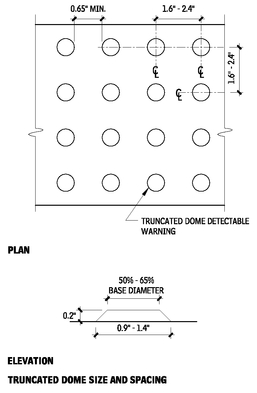
Detectable warnings are required at passenger transit platforms whose edges border a drop-off where no screen or guard is provided. The detectable warning should be a 24-in.-wide strip of truncated domes, contrasting with the adjacent walking surface.
Consult applicable codes and federal requirements regarding the current status of the requirements for detectable warnings at hazardous vehicular ways.
ASSISTIVE LISTENING SYSTEMS
Stadiums, theaters, auditoriums, lecture halls, and similar fixedseating assembly areas are required to provide assistive listening systems when an audio amplification system is provided. Courtrooms are required to have assistive listening systems whether or not an audio application system is provided.
Check the applicable requirements for the number of receivers required, as they vary from just over 1 to 4 percent of the total capacity of the assembly area. At least 25 percent of the receivers should be hearing-aid compatible.
Signs should be provided at ticketing areas or other clearly visible locations, indicating the availability of the assistive listening system. Signs should include the International Symbol of Access for hearing loss.
Contributor:
Lawrence G. Perry, AIA, Silver Spring, Maryland.
AUTOMATIC BANKING SYSTEMS AND TRANSPORTATION FARE COLLECTION EQUIPMENT
Where automatic teller machines (ATMs) or fare collection equipment are provided, generally at least one machine is required to be accessible. ICC/ANSI A117.1 lists extensive criteria addressing the input and output requirements of these machines, which are intended to make them usable by someone with a vision or hearing impairment. A117.1 requires operable parts to be not more than 48 in. above the floor or ground.
TELEPHONES
Accessible public telephones are required where coin-operated public pay telephones, coinless public pay telephones, public closed-circuit telephones, courtesy phones, or other types of public telephones are provided. One wheelchair-accessible phone is required on each floor or level where phones are provided; where more than one bank is provided on a floor or level, at least one phone at each bank must be wheelchair-accessible. ICC/ANSI A117.1 requires that all operable parts of wheelchair-accessible phones be located a maximum of 48 in. above the floor or ground. Federal regulations require all new telephone equipment to be hearing-aid-compatible.
VOLUME-CONTROL TELEPHONES
Check applicable requirements for the number of and amplification requirements for telephones with volume control, which vary among the building code and federal requirements. Telephones with volume control must be identified by signs, unless all telephones have volume control.
TEXT TELEPHONES (TTYs)
Consult the applicable standards for the required number and location of TTYs. Model codes, based on the recommendations of the ADAAG Review Committee, provide for an increased number of TTYs based on whether the building is publicly or privately owned and the number of phones at the site, in the building, on each floor, and at each bank of phones. Additional requirements may apply for hospitals, transportation facilities, highway rest stops, emergency roadside stops, service plazas, and detention and correctional facilities. Public TTYs should be identified by the international TTY symbol. Directional signs to TTYs should be provided at banks of public telephones not providing TTYs. In addition, there may be requirements for shelves and outlets at banks of telephones without TTYs, to allow use of a portable TTY.
TELEPHONES
13.64
ACCESSIBLE TOILETS AND BATHROOMS
GRAB BARS
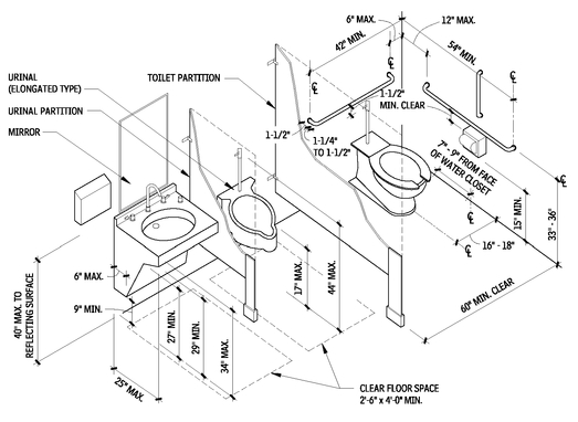
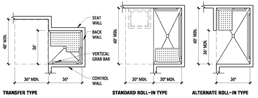
LOCATION OF ACCESSIBLE FIXTURES AND ACCESSORIES
13.65
NOTES
13.65 a. If the partition is greater than or equal to 2 ft-0 in. deep, urinal clear floor spaces must be 3 ft wide.
b. Mirrors located above lavatories, sinks, and vanities must be mounted with the bottom edge of the reflecting surface 40 in. maximum above the floor. Other mirrors must be mounted with bottom edge of the reflecting surface 35 in. maximum above the floor.
c. Vertical grab bars are required by ICC/ANSI A117.1.
Contributor:
Lawrence G. Perry, AIA, Silver Spring, Maryland.
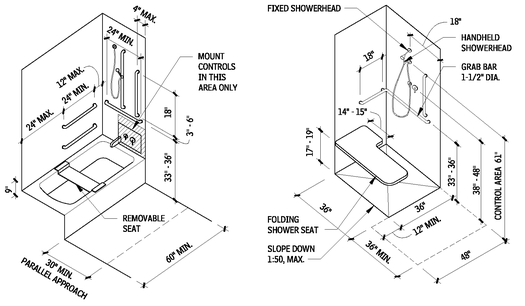
ACCESSIBLE BATHTUB AND SHOWER
13.66
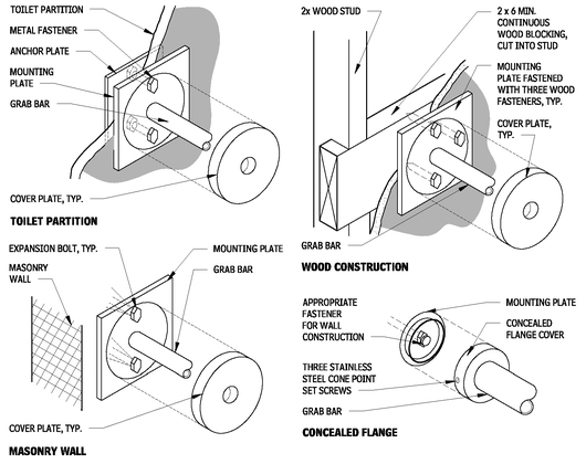
GRAB BAR ATTACHMENT DETAILS
13.67
Size: 1-1/2 in. or 1-1/4 in. O.D. with 1-1/2 in. clearance at the wall.
Material: Stainless steel chrome-plated brass with knurled finish (optional).
Installation: Concealed or exposed fasteners; return all ends to the wall, intermediate supports at 3 ft maximum. Use heavy-duty bars and methods of installation.
Other grab bars are available for particular situations. Consult ICC/ANSI A117.1 and ADAAG requirements, as well as applicable local and federal regulations.
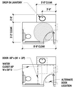
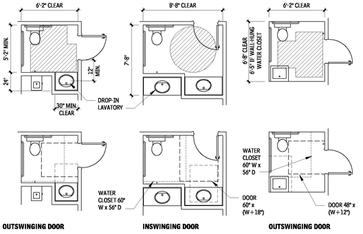
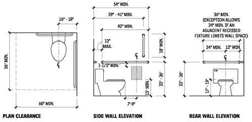
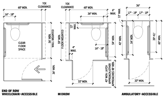
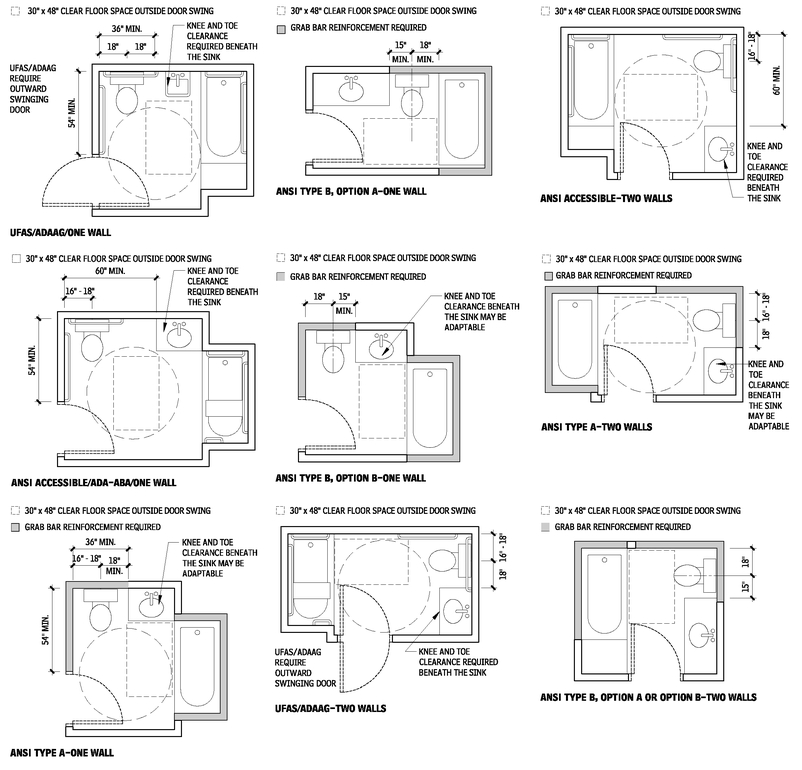
ACCESSIBLE TOILET ROOMS
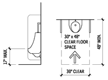
All dimensional criteria in this discussion are based on ICC/ANSI A117.1, and on adult anthropometrics.
• In new construction, all public and common-use toilet rooms are generally required to be accessible.
• Where multiple single-user toilet rooms or bathing rooms are clustered in a single location and each serves the same population, 5 percent, but not less than one of the rooms must be accessible. The accessible room(s) must be identified by signs.
• Single-user toilet and bathing rooms provided within a private office are permitted to be adaptable. Making the room accessible is permitted to involve replacement of the water closet and lavatory, changing the swing of the door, and installing grab bars in previously reinforced walls.
• In accessible toilet and bathing rooms, at least one of each type of fixture and accessory provided must be accessible.
• A wheelchair turning space is required within accessible toilet and bathing rooms.
• Doors are not permitted to swing into the required clear floor space at any fixture, except in single-user rooms, where a clear floor space is provided beyond the swing of the door.
UNISEX TOILET AND BATHING ROOMS
ASSEMBLY AND MERCANTILE OCCUPANCIES
• Recent model codes require accessible unisex toilet and bathing rooms in certain assembly and mercantile occupancies. These unisex rooms are beneficial for parents with small children and for persons with disabilities who require personal assistance in using toilet facilities, as the assistant may be a person of the opposite sex. This requirement applies when a total of six or more water closets (or water closets and urinals) is provided in the facility or in certain occupancy areas.
• Fixtures provided in unisex rooms are permitted to be included in the number of required plumbing fixtures.
• Unisex facilities must be located within 500 ft, and within one floor, of separate-sex facilities. In facilities with security checkpoints, such as airport terminals, unisex facilities must be located on the same side of the checkpoint as the separate-sex facilities they serve.
• Unisex toilet rooms require a single water closet and lavatory, or as an exception, a urinal, in addition to the water closet.
• When bathing fixtures are provided in separate-sex facilities, an accessible shower or bathtub must be provided in the unisex bathing room.
• If storage is provided in separate-sex facilities, it must be provided in the unisex bathing room.
• Doors to unisex toilet and bathing rooms must be securable from within the room.
ALTERATIONS
• Accessible unisex toilet and bathing rooms are permitted in alterations in lieu of altering existing separate-sex facilities in certain conditions.
• Unisex rooms must be located in the same area and on the same floor as the existing inaccessible facilities.
TOILET ROOM LAYOUTS
• Variations are in the direction of the door swing and whether the width or depth is the more constraining dimension. Dimensions show comfortable minimums and preferred dimensions.
• Overall room dimensions include a 2-in. construction tolerance.
• Each layout shows the required clear floor space for the fixtures and the doors. Frequently, the clear floor space at the fixture is more stringent than the 60-in. diameter or the T-shaped maneuvering space required. Both must be considered.
• Door maneuvering clearances: Variables include direction of swing, direction of approach, size of door, and door hardware. See “Accessible Doors” in this chapter.
• Doors to bathrooms are assumed to be 36 in. wide, with a closer and latch for privacy. Where noted, the overall dimension may decrease if there is no closer.
• Maneuvering clearances at the base of water closets are based on American Standard models (floor-mounted tank type and wall-mounted, flush-valve type), mounted according to the manufacturer’s recommendations. Confirm actual water closet dimensions.
NOTES
13.66 a. Vertical grab bars are required by ICC/ANSI A117.1. b. The space in front of the transfer shower must also meet alcove provisions if the adjacent walls confine access to the clear floor space in front of the shower.
Contributors:
Mark J. Mazz, AIA, Hyattsville, Maryland; Lawrence G. Perry, AIA, Silver Spring, Maryland.
• Maneuvering clearances below lavatories are based on American Standard models (wall-hung and mounted in countertop). Confirm actual lavatory dimensions.
SHORT AND COMPACT PLANS
13.68
LAVATORY ON SIDE WALL
13.69
LAVATORY ON OPPOSITE WALL
13.70
TOILET COMPARTMENTS
• Where toilet compartments are provided, at least one compartment must be wheelchair-accessible.
• Where six or more toilet compartments are provided in a toilet room, in addition to the wheelchair-accessible compartment, a 36-in.-wide ambulatory accessible compartment is required.
ACCESSIBLE TOILET AND BATHING FIXTURES
Requirements for accessible residential fixtures are discussed throughout this chapter. All dimensional criteria are based on ICC/ANSI A117.1 and adult anthropometrics, unless otherwise indicated.
WATER CLOSETS AND URINALS
• ICC/ANSI A117.1 allow water closets to be located 16 to 18 in. from the side wall in wheelchair-accessible stalls, and 17 to 19 in. in ambulatory accessible stalls. Other regulations may require this dimension to be 18 in.
• ICC/ANSI A117.1 prohibits other fixtures within the required clearances for the water closet. Previous editions and other regulations allow other configurations with a lavatory within the water closet clearance.
• The top of the water closet seat must be 17 to 19 in. above the floor. Seats must not be sprung to return to a lifted position.
• ICC/ANSI A117.1 requires a vertical grab bar located on the side wall; previous editions and other regulations may not.
• The hatched area on Figure 13.97 indicates the allowable location of the toilet paper dispenser. Outlet must be within the range shown. Dispensers should allow continuous paper flow, not control delivery.
• ICC/ANSI A117.1 allows a stall-type urinal; it does not require an elongated urinal rim for a wall urinal. Other regulations may.
• Manually operated flush controls must be located 44 in. maximum above the floor.
WATER CLOSETS
13.71
Contributors:
Mark J. Mazz, AIA, P.A., Hyattsville, Maryland; Lawrence G. Perry, AIA, Silver Spring, Maryland.
URINALS
13.72
TOILET COMPARTMENTS
• Toe clearance 9 in. high and 6 in. deep is required at the front and at least one side of accessible toilet compartments. Toe clearance is not required when the compartment size exceeds the minimum dimension by 6 in. or more.
• Left- or right-handed configurations are permitted.
• The door to the toilet compartment must be self-closing and have a pull on both sides near the latch.
LAVATORIES
• Knee and toe clearance is required below accessible lavatories. The lavatory overflow is permitted to project into the knee clearance.
• All exposed pipes located beneath accessible lavatories must be insulated or located so as to protect users from contact with the pipes.
• Lavatory controls should be within accessible reach range, be operable with one hand, and not require tight grasping, pinching, or twisting of the wrist. Automatic controls are acceptable. Manually activated, self-closing faucets should operate for not less than 10 seconds.
BATHTUBS
• Bathtub controls, other than drain stoppers, must be located on an end wall between the tub rim and grab bar and between the open side of the tub and the midpoint of the tub width.
• A 59-in. minimum length shower spray unit is required.
• Tub enclosures must not obstruct controls or interfere with transfer from a wheelchair to the tub. Enclosures must not have tracks mounted on the tub rim.
• ICC/ANSI A117.1 does not allow a sink with knee clearance at the foot end of the tub. Other regulations may.
• ICC/ANSI A117.1 requires an 18-in. minimum long vertical grab bar on the control wall, 3 to 6 in. maximum above the horizontal grab bar, which is 4 in. maximum inward from the front edge of the bathtub. Other regulations may not have these requirements.
TOILET COMPARTMENTS
13.73
LAVATORIES
13.74
BATHTUBS
13.75
Contributor:
Lawrence G. Perry, AIA, Silver Spring, Maryland.
SHOWERS
13.76
SHOWER COMPARTMENTS
• Shower compartment thresholds are not permitted to exceed 1/2 in. Design should anticipate water escaping from the compartment.
• A fixed, folding, or removable seat is required in transfer-type compartments. Seats in roll-in showers, where provided, should be located on the wall adjacent to the control wall and should be folding-type seats. Seats can be rectangular or L-shaped; see ICC/ANSI A117.1 for details.
• A 59-in. minimum length shower spray unit is required.
• Shower enclosures, where provided, must not obstruct controls or interfere with transfer from a wheelchair.
• In transfer-type showers, ICC/ANSI A117.1 requires an 18-in. minimum long vertical grab bar on the control wall, 3 to 6 in. maximum above the horizontal grab bar, which is 4 in. maximum inward from the front edge of the bathtub. Other regulations may not have these requirements.
CHILDREN’S FIXTURES
ICC/ANSI A117.1 and ADAAG provide technical requirements based on children’s dimensions and anthropometrics for water closets, toilet compartments, lavatories, and sinks, when used primarily by people 12 years old and younger. The dimensions should be applied consistently within the restroom.
Toilet compartments for children’s use require a depth of 59 in. for both wall-hung and floor-mounted water closets, and a toe clearance of 12 in. high, 6 in. minimum, beyond the partition on the front and one side. Toilet compartments that are 65 in. minimum deep are not required to have toe clearance.
Table 13.77 lists dimensions for water closets serving children, and provides additional guidance specific to the age group served. The specifications chosen should correspond to the age group of primary user and should be applied consistently in the installation of the water closet and the related grab bars and dispensers.
Sinks and lavatories for children ages 6 to 12 with a 31-in. maximum rim or counter surface may have a knee clearance of 24 in. minimum. Parallel approach is permitted at lavatories and sinks used primarily by children ages 5 and younger.
WATER CLOSETS FOR CHILDREN
13.77
ACCESSIBLE RESIDENTIAL BATHROOMS
ACCESSIBILITY STANDARDS FOR BATHROOMS
Although toilet room and fixture design standards were an important part of the first ANSI A117.1 standards in 1961, bathroom standards with mobility features for residential dwellings were not included until the 1981 edition. Four years later, the Uniform Federal Accessibility Standard (UFAS) published nearly identical bathroom standards for dwellings included in federal projects. In most multifamily projects, whether privately or publicly funded, between 1 and 5 percent of the total dwellings must meet the ANSI or UFAS standards for full wheelchair accessibility. The exact scoping requirement depends on the specific codes or laws.
In 1988, the Fair Housing Amendments Act (FHAA) was amended to include protection against discrimination on the basis of disability. The FHAA applies to buildings with four or more dwelling units intended to be used as a residence, whether the housing is for rent or for sale, and whether it is privately or publicly funded.
This includes apartments, condominiums, residential shelters, and long-term care facilities. Although the requirements are less stringent than those found in ICC/ANSI A117.1 Accessible Units and UFAS, the FHAA requirements are more broadly applied to all units in buildings with one or more elevators, and ground floor units in buildings without elevators. The Fair Housing Accessibility Guidelines (FHAG) include two options for bathroom design, designated as Option A and Option B. The primary difference is that Option B provides a more accessible approach to the bathtub. In covered dwellings with two or more bathrooms, all bathrooms must comply with Option A, or at least one must comply with Option B requirements. In covered units with one bathroom, either Option A or B may be used.
The Americans with Disabilities Act (ADA) and the Americans with Disability Act Accessibility Guidelines (ADAAG) provide accessibility requirements for units in transient lodging, medical care and long-term care facilities, and detention and correction facilities. Some residential facilities may be covered by both the ADA and the FHAA, for example dormitories and nursing homes. The final ADA/ ABA Guidelines dated July 23, 2004 revise ADAAG, and will serve as the basis for the minimum standards when adopted by other federal agencies responsible for issuing enforceable standards. These guidelines include updates to requirements for units and also include new requirements for “Residential Units” that are not included here. The ADAAG bathroom layouts accompanying this discussion reflect the ADAAG (Appendix A 28 CFR Part 36) criteria and the final ADA/ABA Guidelines for transient lodging. Refer to the Access Board Web site (
www.access-board.gov) for the current status of this adoption process.
ICC/ANSI A117.1 includes the technical requirements for three types of dwelling and sleeping units with mobility features:
• Accessible units: The number of accessible units required by the building code typically is based on the total number of units provided in the facility.
• Type A dwelling units: Type A dwelling units are required by the building code in multifamily residential facilities, including apartment buildings, condominiums, monasteries, and convents. The number of units required to comply with these requirements is generally based on a percentage of the total number of units provided; refer to the applicable building code.
• Type B dwelling units: The requirements for Type B dwelling units are intended to be consistent with the technical requirements of the FHAA.
The technical requirements for the bathrooms vary significantly among these types. Accessible units are most accessible, and they are generally required by the building code in public and institutional residential facilities, including nursing homes, hospitals, detention facilities, dormitories, boarding houses and hotels.
There has been an effort in the code development community to make the technical requirements for residential units in ICC/ANSI A117.1 consistent with those found in the federal requirements. It should be noted that in addition to the guidelines, the regulations are also an important part of these federal laws. To ensure compliance, architects should consult the codes, laws, and appropriate regulations, and carefully verify the requirements applicable to their projects before proceeding with the design and construction of residential housing.
MANEUVERING SPACE
An accessible bathroom must meet specified plan requirements, depending on the standards used. Each bathroom plan must provide the fixture clearances required by the applicable standard. In addition, general maneuvering space must be provided, although the amount of space varies by unit type.
ICC/ANSI A117.1 Accessible Unit and Type A, UFAS, and ADAAG require either a 5-ft diameter circle or a 5-ft T-shaped wheelchair turning area. Maneuvering space can generally include knee and toe space under fixtures and accessories.
Bathrooms in ICC/ANSI A117.1 Type B and FHAG must be “usable” rather than “accessible;” therefore, the minimum maneuvering clearance is less. In these units, there must be enough clear space to position a wheelchair clear of the door swing. This requirement is described as a rectangular space 30 by 48 in. All of the standards permit required floor space for fixtures to overlap with required maneuvering space. ADAAG standards, however, do not permit the bathroom door (even in single-user facilities) to swing into any fixture clearance. In almost all situations, this requirement effectively necessitates that the door swing out into the adjacent hall or bedroom. This has been revised in the final ADA/ABA Guidelines.
BATHROOM ENTRY DOORS
Different unit types require different-size bathroom entry doors. ICC/ANSI A117.1 Accessible Unit and Type A, UFAS, and ADAAG require installation of at least a 3-ft door to provide the full 32-in. clear opening. Additionally, they include requirements for maneuvering clearances. ICC/ANSI A117.1 Type B and FHAG permit a 2 ft 10 in. door clearance to provide a “nominal” 32-in. clear opening; door maneuvering clearances are not required.
GRAB BARS
The grab bar arrangement can influence the floor plan of an accessible bathroom. The grab bar requirements of ICC/ANSI A117.1 Accessible and Type A, UFAS, and ADAAG can become critical factors in water closet and bathroom arrangements. ICC/ANSI A117.1 Type B and FHAG unit grab bar standards permit a shorter side grab bar, and allow the installation of swing-up grab bars, so the wall adjacent to the water closet may be shorter or omitted entirely.
ADAPTABLE FEATURES
In residential bathroom design, adaptability was a new term when introduced in the 1980 ANSI edition. Adaptability, in this case, is defined as “the capability of certain ... elements ... to be altered or added so as to accommodate the needs of persons with or without disabilities, or to accommodate the needs of persons with different types or degrees of disabilities.”
Contributor:
Lawrence G. Perry, AIA, Silver Spring, Maryland.
BATHROOM LAYOUTS
13.78
NOTES
13.78 a. ANSI Accessible refers to ICC/ANSI A117.1 Accessible Units.
b. ANSI A refers to ICC/ANSI A117.1 Type A unit.
c. ANSI B refers to ICC/ANSI A117.1 Type B unit.
Contributors:
Kim A. Beasley, AIA, and Thomas D. Davies Jr., AIA, Paralyzed Veterans of America Architecture, Washington, DC.
In accessible bathrooms, adaptable elements might typically include “removable” base cabinets that can be eliminated, when necessary, to provide knee space below vanities, and hidden wall reinforcing that will facilitate later installation of grab bars around certain plumbing fixtures. It is important that cabinets be of the same quality as those in nonaccessible units and that the flooring and wall finishes be extended beneath and behind so that when the cabinet is removed, the bathroom maintains a finished appearance.
Although the term adaptability is not included in ICC/ANSI A117.1, this standard allows removable base cabinets and reinforcement for the later installation grab bars in ICC/ANSI Type A and Type B units.
OTHER RESIDENTIAL BATHROOMS
As with all custom design, the design of accessible bathrooms for single-family custom homes or remodeling projects should be tailored to the individual homeowners. For example, if a master bathroom is planned for a wheelchair user, the design should reflect that person’s individual requirements and preferences.
PLUMBING FIXTURE REQUIREMENTS
Fixture requirements vary among the common accessibility standards and guidelines. The most significant differences are found between those required to comply with FHAA and the requirements for ICC/ANSI A117.1 Accessible Unit and Type A, UFAS, and ADAAG. The final ADA/ABA Guidelines dated July 23, 2004 revised ADAAG, and will serve as the basis for the minimum standards when adopted by other federal agencies responsible for issuing enforceable standards.
These guidelines include updates to requirements for units as well as new requirements for “Residential Units.” The ADAAG fixture space diagrams shown in Figures 13.79 to 13.81 reflect the ADAAG
(Appendix A, 28 CFR Part 36) criteria, not the final ADA/ABA Guidelines. Refer to the Access Board Web site (
www.accessboard.gov) for the current status of this adoption process.
Approach clearance requirements for the different accessibility standards are illustrated in Figures 13.79 to 13.81. For other requirements, such as grab bar installations or faucet specifications, architects should refer to the code(s) or standard(s) that apply to their projects.
WATER CLOSET STANDARDS
The differences in the minimum clear floor space requirements for water closets are related to the allowed proximity of adjacent fixtures and required locations for grab bars. In ICC/ANSI A117.1 Accessible Units, no other fixture is permitted in the required clearance, and the water closet must be located adjacent to a side wall to accommodate grab bars.
UFAS, ICC/ANSI A117.1 Type A, and ADAAG also require an adjacent side wall, but allow a lavatory with knee clearance 18 in. minimum from the centerline of the water closet. ICC/ANSI A117.1 Type A allows “adaptable” cabinetry beneath the lavatory, provided it can be removed without removing or replacing the lavatory, the flooring extends under the cabinetry, and the walls surrounding the cabinetry are finished. ICC/ANSI A117.1 Type B/FHAA allow a sink or vanity with or without knee clearance 15 in. minimum from the centerline of water closet. The water closet is not required to be adjacent to the side wall, but it must have 18 in. minimum clearance to accommodate the future installation of swing-up or floor-mounted grab bars.
In addition to clearance requirements, UFAS, ICC/ANSI A117.1 Accessible Unit, and ADAAG include provisions for toilet seat height (17 to 19 in. AFF) and the location and operation of flush controls and toilet paper dispensers. ICC/ANSI A117.1 Type A requirements also include seat height (15 to 19 in. AFF) and the location and operation of flush controls. ICC/ANSI A117.1 Accessible Unit, UFAS, and ADAAG specify the extent and location of the required grab bars; ICC/ANSI A117.1 Type A, ICC/ANSI A117.1 Type B, and FHAG require reinforcement for future installation of grab bars.
LAVATORY AND VANITY STANDARDS
The major differences between accessibility standards for lavatories and vanities are related to the need for forward-approach clearance with knee space. All unit types require this approach, with the exception of FHAG/ICC/ANSI A117.1 Type B, which allow a parallel approach centered on the basin. ADAAG, ICC/ANSI A117.1 Accessible Unit, ICC/ANSI A117.1 Type A, and UFAS also include requirements for faucets, mirror height, and pipe protection. ICC/ANSI A117.1 Accessible Unit includes a provision requiring comparable vanity space, in terms of size and proximity to the lavatory, in accessible units as provided in the nonaccessible units in a project.
BATHTUB AND TUB/SHOWER STANDARDS
The accessible bathtub standards also have subtle differences. For bathtubs without permanent seats, ICC/ANSI A117.1 Accessible Unit requires a 30-in. clearance parallel to the length of the bathtub. For bathtubs with permanent seats, ICC/ANSI A117.1 Accessible Unit requires 12 in. beyond the seat to allow room for a wheelchair user to align the wheelchair for transferring to the seat. ICC/ANSI A117.1 Type A requires these same clearances, but allows a countertop or cabinetry (not a sink) at the foot end, provided it can be removed and the flooring extends underneath. UFAS and ADAAG allow an accessible lavatory with knee clearance in the foot end clearance.
WATER CLOSET SPACE REQUIREMENTS
13.79
LAVATORY AND SHOWER SPACE REQUIREMENTS
13.80
Contributors:
Kim A. Beasley, AIA, and Thomas D. Davies Jr., AIA, Paralyzed Veterans of America Architecture, Washington, DC; Rebecca Ingram, Architect, Albuquerque, New Mexico.
BATHTUB SPACE REQUIREMENTS
13.81
FHAG and ICC/ANSI A117.1 Type B provide two bathroom options. Option A allows a parallel approach, which can include a lavatory with knee clearance, or a perpendicular approach into which a toilet may encroach. Option B requires a clear 30 by 48 in. approach parallel to the bathtub, beginning at the control wall. Of these alternatives, Option B is more accessible because it provides greater access to the controls. ICC/ANSI A117.1 Accessible Unit, ICC/ANSI A117.1 Type A, UFAS, and ADAAG all have additional requirements for the location and operation of the showerhead and faucet controls. ICC/ANSI A117.1 Accessible Unit, UFAS, and ADAAG specify the extent and location of the required grab bars; ICC/ANSI A117.1 Type A, ICC/ANSI A117.1 Type B, and FHAG require reinforcement for future installation of grab bars.
TRANSFER-TYPE STALL SHOWER
AND ROLL-IN UNIT STANDARDS
Accessible showers include both transfer stalls (where a bather moves from a wheelchair to a bench or portable seat) and roll-in stalls (where a bather remains seated in a special shower chair and is either pushed by an attendant or self-propelled into the stall). ICC/ANSI A117.1 Accessible Unit, UFAS, and ADAAG require installation of a built-in stall seat in stall type and alternate roll-in type showers. ICC/ANSI A117.1 Type A requires reinforcement for future installation of a shower seat. ICC/ANSI A117.1 Type B and FHAG also require reinforcement, except in showers that are greater than 36 by 36 in. ICC/ANSI A117.1 Accessible Unit, ICC/ANSI A117.1 Type A, UFAS, and ADAAG include requirements regarding the location and operation of the showerhead and operating controls, threshold configuration, and water temperature. ICC/ANSI A117.1 Accessible Unit, UFAS, and ADAAG specify the extent and location of the required grab bars; ICC/ANSI A117.1 Type A, ICC/ANSI A117.1 Type B, and FHAG require reinforcement for future installation of grab bars.
ACCESSIBLE RESIDENTIAL KITCHENS
ACCESSIBILITY GUIDELINES
The 1980 ANSI A117.1 and the 1984 UFAS were the first to include kitchen design standards with features for wheelchair users. In most multifamily housing, between 1 and 5 percent of the total dwelling units must be wheelchair-accessible, depending on local building codes or federal standards. The kitchen standards in the 1988 Fair Housing Amendments Act (FHAA), a federal civil rights law, include requirements for “usable kitchens” in multifamily housing. Fair Housing standards must be applied to between 20 and 100 percent of the total project units, with some exceptions, depending on the configuration of the buildings, whether they are equipped with a passenger elevator, and the site topography.
The ADA/ABA Guidelines provide new requirements for “Residential Units,” which are not included here. Refer to the Access Board Web site (
www.access-board.gov) for the current status of this adoption process.
The ICC/ANSI A117.1 includes the technical requirements for three types of dwelling units with mobility features, and the technical requirements for the kitchens vary among these types:
• Accessible units: These units are most accessible and they are generally required by the building code in public and institutional residential facilities, including dormitories, boarding houses, and hotels.
• Type A units: These are typically required by the building code in multifamily residential facilities, including apartment buildings. The number of units required to comply with these requirements is based on a percentage of the total number of units provided.
• Type B units: These are intended to be consistent with the technical requirements of the Fair Housing Amendments Act.
Architects should carefully verify which kitchen requirements are appropriate for their specific projects because these unit types have very different design standards. HUD has designated “safe harbors” for compliance with the FHAA.
Accessible kitchens should reflect conventional layout principles with regard to proper workflow and functional adjacencies. As with conventional custom design, accessible kitchen designs for single-family custom homes or remodeling projects should suit the specific needs and preferences of the homeowners.
FIXTURE AND APPLIANCE REQUIREMENTS
The three general types of wheelchair standards for residential kitchens are:
• Overall kitchen maneuvering clearance
• Approach clearances for individual fixtures and appliances
• Other fixture specifications such as basin depths, switch locations, and faucet configurations
ICC/ANSI A117.1 Accessible Unit, ICC/ANSI A117.1 Type A, and UFAS standards for appliances and plumbing fixtures are much more accessible than ICC/ANSI A117.1 Type B/FHAG, as detailed in Table 13.108. All require that sufficient clear floor space be provided at fixtures or appliances to accommodate either a parallel or front approach, depending on the applicable design standard.
Fair Housing guidelines and most building code standards require a clear floor space at most kitchen fixtures and appliances. This space can permit a parallel or a perpendicular (front) wheelchair approach, depending on the fixture or appliance selected or the decision of the designer. HUD has interpreted its FHAA guidelines to require centering of the clear floor space on the appliance or fixture. This is not a requirement of ICC/ANSI A117.1.
Some clearance standards do not have a functional basis, however. For example, in order to be useful, a parallel approach to a dishwasher must be offset to allow the bottom-hinged door to be fully lowered. An adjacent knee space at either the kitchen sink or an open, end-of-counter location provides optimum wheelchair access to a dishwasher. A parallel approach to a refrigerator is more practical than a front approach because the user’s longer horizontal reach will allow full access to the interior.
Appliance clearances may depend on specific appliance features. For example, oven clearances depend on whether the door is sideor bottom-hinged. Overall maneuvering clearances must take into consideration the depth of any projecting appliances. If the kitchen design is based on specific assumptions regarding appliances, the architect should carefully note that fact on the drawings to ensure compliance.
A critical point regarding clear floor space and kitchen fixtures and appliances is the requirement to precisely center the floor space on the centerline of the appliance or fixture. Although this requirement was not explicitly stated in the Fair Housing guidelines, HUD interprets this to be a Fair Housing kitchen and bathroom requirement. In a kitchen plan, the impact can be significant. For example, to provide a parallel approach, fixtures or appliances less than 48 in. wide must be offset from either an end wall or an inside counter corner. A 30-in. refrigerator, for example, must be located 9 in. away from an end wall, or a forward approach must be provided; a 24-in. dishwasher must be located 12 in. away from an inside counter corner.
FLOOR SPACE AND KNEE SPACE REQUIREMENTS FOR FIXTURES AND APPLIANCES
13.82
NOTE
13.81 ANSI A allows for removable cabinetry in the clearance at the foot end. ADAAG and UFAS allow a lavatory.
13.82 a. Unless there is no conventional cooktop or range. b. Removable base cabinets permitted.
c. The door in the open position must not obstruct the sink or dishwasher approach clearances.
d. Side-hinged ovens are required to have a work surface with knee clearance adjacent to the latch side; bottom-hinged ovens may have the work surface with the clearance on either side.
e. Side-hinged ovens are required to have a counter adjacent to the latch side; bottom-hinged ovens may have the counter on either side.
Contributor:
Lawrence G. Perry, AIA, Silver Spring, Maryland.
Requirements for general maneuvering space within the kitchen and for counter heights also vary among standards. All require a minimum clearance between counters, countertops, appliances, or walls of (1) 40-in. in a galley aisle where a required fixture or work area knee space is provided or (2) a 60-in. aisle in U-shaped kitchens. In ICC/ANSI A117.1 Accessible Units, a pass-through kitchen must have two points of entry. If it is enclosed on three contiguous sides, it is considered a U-shaped kitchen and must have a wheelchair turning area. ICC/ANSI A117.1 Accessible Unit, ICC/ ANSI A117.1 Type A, and UFAS require a work surface either with an adjustable-height counter or a fixed counter at a height of 34 in. ICC/ANSI A117.1 Type A allows removable base cabinets for this work surface and the sink. ICC/ANSI A117.1 Type B/ FHAG does not include requirements for counter heights.
ICC/ANSI A117.1 ACCESSIBLE PASS-THROUGH AND ACCESSIBLE U-SHAPED
13.83
NOTE
13.83 A wheelchair turning area and accessible sink and work surface are required. In pass-through kitchens, the required turning area may include knee and toe clearances under the sink or work surface.
ICC/ANSI A117.1 TYPE A MINIMUM CLEARANCE AND TYPE A U-SHAPED
13.84
A wheelchair turning area and accessible or adaptable sink and work surface are required. In galley kitchens (minimum clearance) the required turning area may include knee and toe clearances under the sink or work surface.
ICC/ANSI A117.1 TYPE B MINIMUM CLEARANCE AND TYPE B U-SHAPED
13.85
A U-shaped counter arrangement must include a 5-ft clearance between the opposing counters (or appliances or walls) to comply with ICC/ANSI A117.1 Accessible Unit, ICC/ANSI A117.1 Type A, and ICC/ANSI A117.1 Type B. FHAA guidelines require a 5-ft clearance if a sink, range, or cooktop is installed in the base leg of the U. If the base leg fixture includes a knee space or removable base cabinets, the 5-ft clearance is not required.
NOTE
13.85 A wheelchair turning area and accessible or adaptable sink and work surface are required.
APPROACH DIAGRAM FOR FIXTURES OR APPLIANCES
13.86
KITCHEN SINK AND DISHWASHER
13.87
Locating the kitchen sink next to the dishwasher has accessibility benefits as well as functional advantages. The sink knee space provides convenient access for a wheelchair user to the adjacent dishwasher. The sink itself should be a shallow unit with easy-to-operate faucets. A tall spout and a pullout spray attachment are also recommended. Garbage disposals must be offset in order to provide full knee space under the sink.
KITCHEN STORAGE
13.88
The design of kitchen storage space for wheelchair users should provide both visual and physical access to cabinets, drawers, and pantries. Base cabinets, for example, can be specified to include pullout shelves or drawers that will provide easy access to items stored in the back of the cabinets. Similarly, shelf racks on pantry doors make it easier for the user to find and reach stored items.
STOVES AND COOKTOPS
13.89
A range or cooktop should have front- or side-mounted controls so the seated user does not need to reach over the heated surfaces. A smooth cooktop surface allows pots to be slid, rather than lifted, on and off the burners. Separate cooktop and oven units allow the alternative of providing knee space below the cooking surface, although this arrangement can also create safety issues.
REFRIGERATORS
13.90
Side-by-side models offer the user both freezer and refrigerator storage at all height levels, from the floor to the top shelf. Overand-under models can also be a satisfactory choice for many wheelchair users. Models with narrower doors are easier to operate, and the desired parallel access is easier to provide if the refrigerator doors swing back a full 180°.
ADAPTABLE FEATURES
The term adaptability is defined as “the capability of certain . . . elements . . . to be altered or added so as to accommodate the needs of persons with or without disabilities.” For accessible kitchens, adaptable elements might include removable base cabinets that can be eliminated to provide knee space below countertops, or adjustable-height countertop sections that can be raised and lowered. With adaptable cabinets, the flooring must extend beneath, and the walls must be finished, so that when the base cabinet is removed, the kitchen maintains a finished appearance.
Contributors:
Lawrence G. Perry, AIA, Silver Spring, Maryland; Rebecca Ingram Architect, Albuquerque, New Mexico.
