14
COMPUTING TECHNOLOGIES
INTRODUCTION
Computing technologies evolve rapidly, and their integration into the profession of architecture matches—if not exceeds—the pace of their development. Some technology-based tools are well established in architectural practice; others have unknown potential in their application to design, visualization, or project delivery.
Architects navigate between two attitudes toward computing technologies:
• Technology facilitates: It can help architects do what they have always done, but better, faster, and/or cheaper.
• Technology transforms: It can reshape what architects do, changing the premises upon which they operate.
An example of the first attitude are those firms that have changed the way they deliver services through building information modeling (BIM), but design within relatively conventional boundaries. An example of the second attitude are architects who use computing technology to explore design parameters too complex to study using analog techniques, which may include non-Euclidian geometries or precise airflows in and around a building. The project delivery for this second approach is not necessarily radically different from conventional delivery but is often altered because the highly specialized data can’t be manipulated through conventional means.
Most practices experiment with a range of applications for computing technology depending on the project; sometimes technology facilitates, sometimes it transforms. The variety of approaches have one thing in common, however: the architect plays a crucial role in the creation, coordination, and general management of data. Judging which technology to use and deciding on which tool to apply toward what end has become one of the most critical activities in which architects engage.
This chapter outlines the fundamental tools found in building information modeling (BIM).
Renée Cheng, University of Minnesota
BUILDING INFORMATION MODELING (BIM)
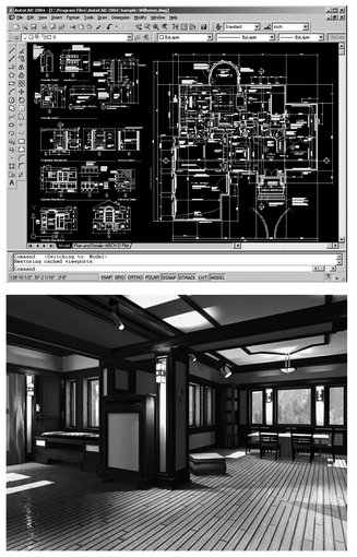
A data model in any given domain describes the attributes of the entities in that domain, as well as how these entities are related to each other. All computer programs deal with some kind of data, so they must have some type of underlying data model. Traditional 2D CAD and generic 3D modeling programs such as AutoCAD, MicroStation, Autodesk VIZ, and form • Z internally represent data using geometric entities such as points, lines, rectangles, planes, and so forth. Thus, although these applications can accurately describe geometry in any domain, they cannot capture domain-specific information about entities. The drawings and models of buildings created with these applications don’t carry much information about the building itself, and are essentially “dumb.” They are used primarily for producing documentation and for visualization.
To overcome the limited intelligence of general-purpose geometric representations, every design-related industry has been developing and using object-based data models that are specific to their domains. In the case of the building industry, both researchers at universities and commercial software vendors have worked to develop a data model that is constructed around building entities and their relationships to one another. Geometry is only one of the properties, of these building entities; thus, its primacy is greatly reduced, even though the interface to create the model is still primarily graphic. Such a data model is rich in information about the building, which can be extracted and used for various purposes, be it documentation, visualization, or analysis.
Building information modeling, (BIM) is the term that has been coined to describe the use of such a model. Several software applications are now available that are built upon this concept, such as ArchiCAD, the Bentley Building suite, the Autodesk Revit suite, and others.
BIM in itself is not a new concept. It has been the subject of architectural CAD research since the mid-1970s, when the earliest attempts were made to develop integrated design systems that could support a suite of applications capable of operating together, rather than just individually. In the industry, Graphisoft’s now 20-year-old solution, ArchiCAD, had building modeling capabilities right from its start. However, what is new is the push to replace CAD with BIM as the de facto standard in the building industry for integrating architecture, engineering, and construction. BIM is continuing to gain momentum rapidly in the building industry, and it is anticipated that most of the transition from CAD to BIM will be completed by the year 2010.
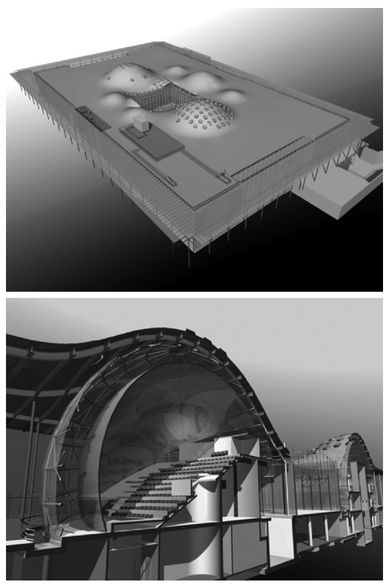
EXAMPLES OF APPLICATIONS THAT USE GEOMETRIC DATA MODELS. TOP: A BUILDING DRAWING IN AUTOCAD. BOTTOM: A ROOM INTERIOR MODELED USING FORM•Z
14.1
Source: Auto • Des • Sys, Inc.
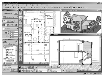
EXAMPLE OF USING A BIM APPLICATION, ARCHICAD, FOR BUILDING DESIGN: THE OPEN WINDOWS SHOW A PLAN, SECTION, AND 3D VIEW OF THE SAME BUILDING DATA MODEL
14.2
Source: Graphisoft
HOW BIM OVERCOMES THE LIMITATIONS OF CAD
Traditional 2D CAD technology has dominated the construction industry for decades, and technological progress has been severely constrained by the limited intelligence of such applications in representing buildings and the capability to extract the relevant information from the representation that is needed for design, analysis, construction management, operation, and so on. Drawings are no longer done manually, but the ubiquitous use of CAD applications in creating drawings has not revolutionized the construction industry in any way. CAD continues to have all the problems associated with manual drafting:
• It is tedious and time-consuming to create separate plans, sections, elevations, details, and so forth, of the same building.
• Any change made must be manually updated in all drawings and reports.
• There is no guarantee of accuracy, consistency, or completeness.
• Coordinating work based on these drawings between the different professionals is extremely difficult.
• Conflicts and errors are detected in abundance at the construction site, necessitating expensive fixes.
• At the end of the process, the owner/operator has nothing but a nonintelligent 2D representation of the building on which to base a lifetime of management, operation, and maintenance.
Analysis and evaluations of energy efficiency, circulation, egress, and other aspects of the building, haven’t really become an integral part of the design process as the building data is not available in any intelligent format and has to be tediously reentered into analysis tools. As a result, the quality of the building suffers. In short, CAD simply replicates the processes of manual drafting by reducing building representations to dumb graphic entities and does little to reduce the inefficiency, waste, errors, and escalating costs that are all too common in the design, construction, and operation of a building.
Unlike CAD, which is general-purpose, BIM is specific to building design: it represents a building using intelligent objects that know about their properties and about their relationship to other objects. Therefore, with BIM, a full 3D representation of the building can be created that simulates how it would be in real life; from this information-rich model, any kind of data needed for design, analysis, visualization, documentation, construction management, operation, and so on, can be derived.
The potential benefits of implementing BIM are manifold:
• Because it is customized for building design, it is faster and easier to create and edit a building model in a BIM application, compared to developing the drawings of the building in a CAD application.
• Once the model is created, all other requirements, including 2D documentation, schedules, reports, 3D renderings, and animations, can be automatically derived from it, improving speed and efficiency.
• All graphical and tabular views of the building are automatically synchronized when a change is made to the model, eliminating the inconsistencies found in construction documents created with conventional CAD software.
• The minimization of drafting allows greater focus on design.
• Interdisciplinary collaboration can be significantly improved, as it will be based on a shared building model.
• Better support for analysis and evaluation tools will allow the building to be thoroughly and vigorously tested before it is built, instituting much higher standards of quality control than those in place today.
• Conflicts are easier to identify in the building model and can be detected during the design phase, which can reduce the expensive fixes at construction time.
• The model created during the design phase can be reused for subsequent phases such as construction and facilities management, saving costs.
• The use of a “live” model for building maintenance can reduce operating costs significantly throughout the lifetime of the building.
In general, BIM is a technology that has the potential to integrate and dramatically streamline operations and processes in the architecture, building, and construction industries.
BIM AND RELATED TECHNOLOGIES
BIM does not work in isolation. What makes it particularly powerful in contrast to CAD is a host of related tools and technologies dealing with different aspects of building design and construction that work with it. This section provides an overview of various applications currently available that are either BIM applications or are complementary to BIM.
CORE BIM APPLICATIONS
The core tools for creating BIM models for architectural, structural, and HVAC, electrical, and plumbing design, as well as for constructability include the following commercially available applications.
BENTLEY BUILDING
The Bentley Building suite includes Bentley Architecture, Bentley Structural, Bentley Mechanical Systems, and Bentley Building Electrical Systems. All these solutions are built on top of Bentley’s existing CAD platform, MicroStation, and its vertical extension for the building industry, Triforma. This coordinates with Bentley’s belief in “not starting over” with a new solution for BIM, but providing an evolutionary ramp for users to transition from CAD to BIM.
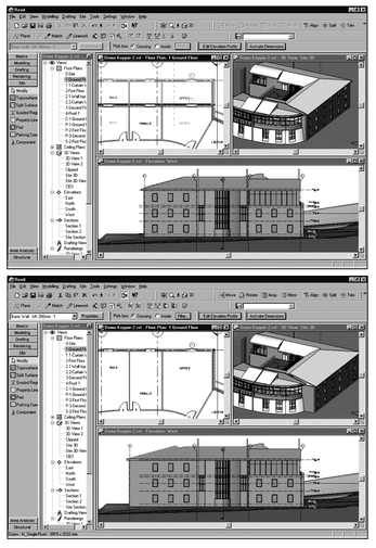
EXAMPLE OF HOW A CHANGE TO THE FOOTPRINT OF THE REAR WING MADE TO THE MODEL IN A BIM APPLICATION, REVIT (SHOWN IN THE UPPER IMAGE), IS AUTOMATICALLY REFLECTED IN ALL THE VIEWS (SHOWN IN THE LOWER IMAGE)
14.3
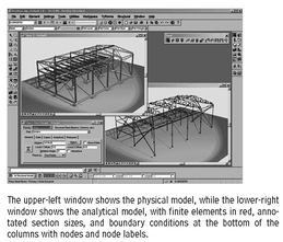
EXAMPLE OF A BUILDING PROJECT WITH STEEL FRAMING AND CONCRETE FOUNDATIONS, DESIGNED USING BENTLEY STRUCTURAL.
14.4
Source: Bentley
Bentley takes a “federated database” approach to BIM, meaning that not all the data related to the building is centralized in a single building model; instead, it is distributed across multiple applications and data stores in a coordinated fashion. Because the building data is decentralized rather than maintained as a monolithic block in a single model, it lends itself more easily to distributed work processes and sharing of information among design teams in multiple offices, as well as making the application more efficient for large projects.
ARCHICAD AND GRAPHICSOFT CONSTRUCTOR
Graphisoft offers ArchiCAD for architectural design, and Graphisoft Constructor for construction modeling. The core strengths of ArchiCAD are:
• A comprehensive feature set for the core architectural tasks of 3D building modeling, 2D documentation, and visualization
• A TeamWork module for collaboration that partitions the building model intelligently so that multiple users can work on it
• Support for openness with a full-fledged application programming interface (API), which allows the application to be customized, and add-ons to be developed to expand its capabilities
• Compatibility with Industry Foundation Classes (IFC) (see the later subsection, “Interoperability and the IFC Building Model”), which enables ArchiCAD to interoperate with other building applications for energy analysis, cost estimation, scheduling, and construction management.
ArchiCAD is based on the single model concept. The Constructor application includes the ArchiCAD modeling system for creating 3D construction models, a 4D sequencer for automatically linking the construction model to the project schedule, thus enabling different schedule alternatives to be analyzed, and a connector to a related estimating application.
EXAMPLE OF A CONSTRUCTION MODEL OF A PROJECT CREATED WITH GRAPHISOFT CONSTRUCTOR
14.5
Source: Graphisoft
ALLPLAN
Nemetschek’s Allplan family of products includes Allplan Architecture for architectural design, Allplan Engineering for all areas of construction engineering, Allplan Steel for steel design, and Allplan Precast Concrete for the design, manufacture, and delivery of Shop fabricated concrete elements.
AUTODESK REVIT
The Autodesk Revit family of products includes Autodesk Revit Building for architectural design, Autodesk Revit Structure for structural design, and an application for HVAC, electrical, and plumbing design The highlights of the Revit products are:
• A single building model
• A simple, elegant, and intuitive interface
• Parametric building components that simplify the creation and editing of the building model
• Intelligent built-in relationships among building components, as well as the capability to define custom relationships and dimensional constraints, all of which are maintained when changes are made
• Automatic generation and coordination of all views and documents, including schedules
• Instant update of all views when any change is made to the model, eliminating inconsistencies
• Immediate availability of 3D views, contributing to a more interactive design experience
REAL-WORLD EXAMPLE: LOBLOLLY RESIDENCE
To illustrate the application of BIM software, a real-world example is included here. It demonstrates how the Revit family of products was used in the construction of a single-family residence, the Loblolly house, in Taylors Island, Maryland, on the Chesapeake Bay.
This 1,800 sq ft weekend house was designed by KieranTimberlake Associates (KTA) from Philadelphia, Pennsylvania. With a tight construction schedule and without access to skilled local labor, the architects embraced the precision of off-site shop fabricated, site assembled construction. This necessitated a three-dimensional understanding of the building and its components, which led to their use of BIM software.
KTA’s systematic approach to Loblolly House allowed the architects to seamlessly combine standard on-site with unconventional off-site construction strategies. Use of Autodesk’s BIM software, Revit, enabled them to improve communication among themselves, engineers, fabricators, and contractors, to collapse all phases of the project into a virtual snapshot. Design decisions were made in tandem with detailing, building system, fabrication, and shipping decisions.
The holistic nature of a single virtual model circumnavigated many of the unknowns that slow down traditional building processes. By understanding Revit’s capabilities, as well as its limitations, KTA could customize the software in response to the specifics of the project. In many cases, they had to reteach the software how to “behave” with respect to issues of shop fabrication and modular construction. Proof of their mastery of the software is evident in the project’s 30-day overall construction schedule.
Aside from the advantages of designing in three dimensions, this holistic approach allowed for more efficient coordination between systems and components, as well as more effective management of part schedules and cost models. With BIM software, one model is the sole source of all project information: it drives all details, fabrication drawings, finish schedules, and parts lists. As a shop fabricated project, this degree of control became very important for KTA in Loblolly House.
This example describes the attributes and benefits of Autodesk’s Revit BIM software by examining each of the major construction components in the project: scaffolding, framing, cartridges, boxes, and skin.
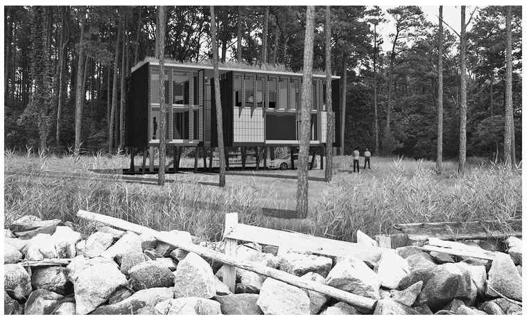
LOBLOLLY HOUSE-EXTERIOR RENDERING FROM BAY
14.6
View of Loblolly House from Chesapeake Bay.
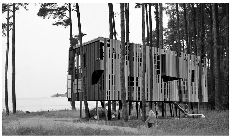
LOBLOLLY HOUSE-EXTERIOR RENDERING FROM DRIVEWAY
14.7
View of the approach to Loblolly House from the driveway.
SCAFFOLDING
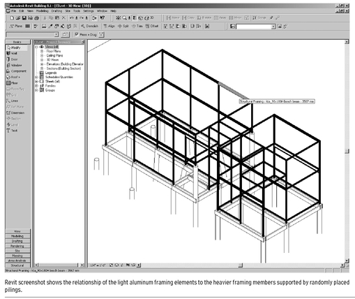
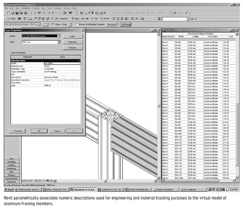
Fabricators extruded the aluminum profiles, which composed the structural frame, cut them to size, then shipped them to the site for assembly. The characteristics of these profiles required a great degree of accuracy, so KTA created a library of aluminum profiles within the Revit model. This enabled them to assemble the frame virtually, much as it would be erected on-site. Each aluminum component contained embedded data, including the size of the profile, length, manufacturer and distributor information, and cost.
Modeling the project in Revit also allowed KTA to accurately study sequencing, detailing, and tolerances during the early design phases of the project. In the case of the scaffolding and all of the project’s construction components, BIM software shortened the onsite assembly of all building elements above the piling foundation to an astonishing two weeks.
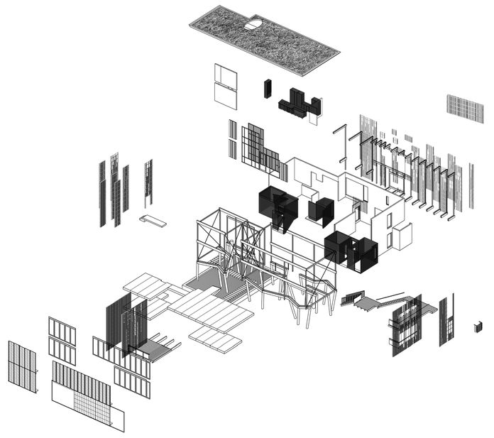
LOBLOLLY HOUSE-EXPLODED DRAWING OF COMPONENTS
14.8
Exploded axonometric of Loblolly house with its four major components: scaffolding, cartridges, boxes, and exterior skin.
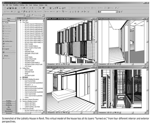
LOBLOLLY HOUSE-FOUR PERSPECTIVES
14.9
LOBLOLLY HOUSE-FRAMING
14.1-0
FRAMING
KTA used the schedule produced from the embedded information in Revit for a number of important purposes: coordination with the structural engineer, development of a cost model, and, most importantly, as a parts list for purchasing this material. Having a single model to which all participants in the design, fabrication, and construction of Loblolly House could refer greatly simplified communication and coordination of changes. This meant that material, detailing, and cost considerations found their way into the project very early in its development. Traditional, two-dimensional construction drawings gave way to a holistic virtual model.
LOBLOLLY HOUSE-DETAIL OF ALUMINUM EXTRUSION
14.11
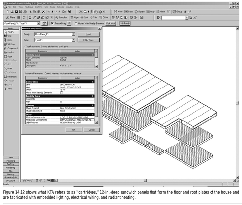
LOBLOLLY HOUSE-FLOOR AND ROOF DECK
14.12
CARTRIDGES
Shop fabricated elements that KTA refers to as “cartridges” formed the floor, ceiling, and roof. These 12-in.-deep sandwiches arrived at the site with mechanical and electrical components installed, including lighting, floor receptacles, and radiant heating. The architects divided the 4-ft-wide panels into types according to their length dimension, which varied according to the floors and space. Models of these components, which included all building materials and finishes, informed KTA’s approach to standardizing them.
This made the fabrication process more efficient. Because manufacturing limitations and the confinements of the structural frame dictated the dimensions of the panels, the components emerged almost as furniture, with restrictions built into their parameters. Within each floor/roof panel type, KTA embedded a schedule of facility service components. Again, this enabled them to produce a schedule that included the panel type, the number of recessed light fixtures within each panel, the number of floor receptacles, and so on. In addition to this information, the fabricator utilized the model as a base for fabrication drawings, eliminating the need for traditional construction drawings.
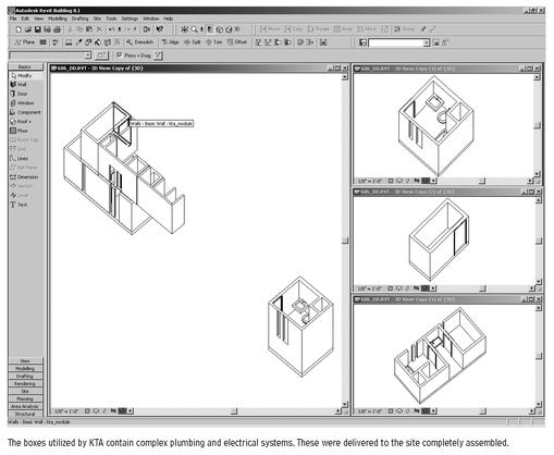
LOBLOLLY HOUSE-TWO FLOATING ROOMS
14.13
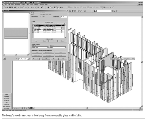
LOBLOLLY HOUSE-WOOD RAINSCREEN
14.14
BOXES
KTA describes boxes as spatial units fabricated off-site that contain the most complex and intricate elements of the house. In the kitchen box, fabricators constructed all cabinetry and fixtures as large furniture with integrated fixtures and systems, connected on-site to waiting utility hookups in the lateral coffers. In bathroom, closet, and mechanical boxes, KTA conceived of floors, walls, ceilings, glazing, roofs, finishes, fixtures, drainage systems, power, and lighting as being finished within the factory and lifted into place at waiting utility hookups.
Modeling these objects in 3D informed KTA’s approach to on-site erection. Because of aluminum frame conflicts, certain structural members were erected after modules were in place. The heightened understanding of interaction among systems informed the assembly strategy. As with other components, the Revit model enabled the architects to produce finish schedules, plumbing fixture schedules, and door schedules for the boxes. This was a beneficial communication tool for fabricators and manufacturers.
EXTERIOR SKIN
The construction team lifted and attached wood-framed, shop fabricated wall panels with a cedar rainscreen to the structural frame. Windows and glazing were also installed off-site. Transparent and translucent panels were off-the-shelf products designed with custom-hinged and sliding assemblies. Fabricators produced these off-site as multilevel units before attaching them to the structural frame on-site. Offset 16 in. from a fully retractable, double-glazed storefront, the whole assembly created a high-performance cavity wall.
Unlike typical walls built on-site, these wall modules had to respect the limitations of shipping. Therefore, awareness of their parameters was particularly useful during fabrication. KTA understood the performance requirements of constructing a functional rainscreen wall. Using Revit allowed them to closely monitor the relationship between off-the-shelf and custom components to render the screen operationally sound.
OTHER APPLICATIONS RELATED TO BIM
All component specification information is captured within a BIM model, which means that any kind of data needed for design, analysis, visualization, documentation, construction management, operation, and so on, can be derived from it, thus allowing the building to be simulated as it would be in real life. Some tools that work with the information in a BIM model are already available, and as the use of BIM becomes more widespread, future development is progressing for many more tools dealing with all aspects of design, construction, and operation.
BIM tools currently available include:
• Tools that check a BIM model for design and modeling errors: The best example of this tool category is the Solibri Model Checker, which “spell-checks” a BIM model to detect potential problems, conflicts, or design code violations, thereby ensuring the integrity of the model for downstream building analysis applications. It works primarily with a building model described in the IFC format (see the next subsection, “Interoperability and the IFC Building Model”).
• Tools that can detect conflicts and spatial interferences between the different disciplinary BIM models: One of the key benefits of BIM is its capability to facilitate multidisciplinary collaboration, particularly when BIM is being used by all the different disciplinary professionals involved in a project. This category of tools includes the architectural, structural, and HVAC components. Leading examples of such tools are the Bentley Interference Manager, which works with all the Bentley Building solutions, and the Clash Detective module in NavisWorks, which is a suite of applications for 3D design publishing and review that works with many different file formats.
•
Tools for energy analysis: These tools have a long history in the architecture, engineering, and construction (AEC) industry and have been used since the advent of computing. Prior to BIM, using these tools involved a great deal of manual entry of the building data, a tedious process that was prone to inaccuracy. With BIM, the building data is already available in a semantically meaningful form and the data can be directly input to an energy analysis tool. A leading example is Green Building Studio, a Web-based application that works with a gbXML file exported from several BIM applications and uses the building information it needs to perform a DOE-2 energy simulation. It allows a proposed design to be quickly evaluated for energy performance and makes it easy to compare the simulation results for multiple options by displaying them together in one table. Another example is ECOTECT, which allows daylighting analysis, as well as thermal analysis.
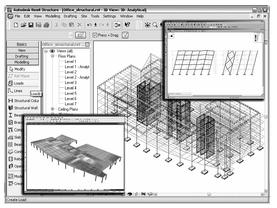
SCREENSHOT SHOWING BIDIRECTIONAL LINKS BETWEEN REVIT STRUCTURE AND STRUCTURAL ANALYSIS AND DESIGN APPLICATIONS
14.15
Source: Autodesk
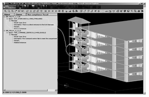
NONCOMPLIANCE RESULTS DETECTED BY E-PLANCHECK FOR A SPECIFIED CLAUSE IN A BUILDING. WHEN VIEWED IN COLOR, THE PROBLEM AREA IS HIGHLIGHTED IN RED IN THE VIEWER
14.16
Source: Courtesy of Novacitynets Pte. Ltd., Singapore
• Structural design and analysis tools:Similar to energy analysis tools, these tools also have a long history of use in the industry and have also traditionally relied on manual reentry of the building data. Now, BIM structural modeling tools such as Bentley Structural and Autodesk Revit Structure automatically link to structural design and analysis tools such as ETABS, STAAD.Pro, RAM Structural System, and RISA-3D. Some BIM applications provide a bidirectional link to the structural analysis tools, which not only automatically input the analytical model of the structure to those tools but also use the results of the analysis to automatically update the physical model and all the related documentation.
• Cost estimating tools: For cost estimating, BIM again removes the need for tedious, manual entry of building data into estimating tools, and provides the capability to directly link to the building model for quantity takeoff. Examples include Timberline Precision Estimating and Graphisoft Estimator. Graphisoft Estimator includes not only a model-based estimating system, which extracts quantity information from the construction model for producing estimates quickly and accurately, but also a traditional estimating system for easing the transition from manual takeoff-based estimating to model-based estimating. Additionally, it includes modules that divide the resources created by the estimating application into production zones and generate procurement requirements. Cost estimating modules also contain a 5D reporting system (i.e., 3D model plus time sequence plus cost) that uses the construction model as the link between cost and time and produces cost-loaded schedules for financial analysis.
• Specifications tools: Still in its infancy, only one example exists of a specifications tool that works with BIM. This is e-SPECS by InterSpec, which automatically creates and updates preliminary project specifications of a Revit BIM model, ensuring their coordination and accuracy.
• Code-checking tools: Of the various analysis and evaluation tools that can be supported by BIM, code-checking stands near the top of the list as one of the areas ripe for automation. It is well known that the process of checking code manually has many problems. It is very labor-intensive and time-consuming, prone to inconsistency (because codes can be interpreted differently by different individuals), and is usually not comprehensive because of time constraints. Because a BIM model is so information-rich, it should be able to support at least a partial code check. A system for automated code checking called CORENET e-PlanCheck has been under development in Singapore for several years. It is now being tested before a full public release. Like many of the analysis tools described in this section, it works on the basis of the IFC format.
INTEROPERABILITY AND THE IFC BUILDING MODEL
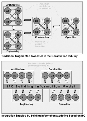
Most BIM applications by commercial vendors have proprietary internal data models and so cannot communicate their rich building information directly with each other unless the vendors develop specific translators for this purpose. Neither can they communicate with other third-party analysis or evaluation tools unless a link has been custom-developed or the product has an API. This inhibits the free flow of building information across the various applications used by the individual players, becoming an impediment to achieving the full potential of BIM. What is required is that these applications be able to easily “interoperate,” which is where the Industry Foundation Classes (IFC) comes in.
THE IFC MODEL
The IFC is an object-based building data model similar to that of commercial BIM applications, except that it is nonproprietary. It has been developed by the International Alliance for Interoperability (IAI), a global consortium of commercial companies and research organizations founded, in 1995, as an industry-based not-for-profit organization. The IFC model is intended to support interoperability across the individual, discipline-specific applications that are used to design, construct, and operate buildings by capturing information about all aspects of a building throughout its life cycle. It was specifically developed as a means to exchange model-based data between model-based applications in the AEC and facilities management (FM) industries, and is now supported by all of the major CAD/BIM vendors, as well as an increasing number of downstream analysis application vendors. With 14 chapters in 19 countries and 650 member companies funding its development, it is a truly global effort.
Because the IFC is an open data exchange format that captures building information, it can be used by the commercial BIM applications to exchange data with each other. This requires the application to be IFC-compliant, which means that it is capable of importing and exporting IFC files. Applications are assigned the IFC-compliant tag by going through an IAI-supervised product certification process. The IFC model specification is posted publicly and is accessible to anyone, so developers can work with it and build the necessary IFC import and export capabilities into their applications.
Looking at the actual IFC model itself in some more detail, it represents not just tangible building components such as walls, doors, beams, ceilings, furniture, and so on, but also more abstract concepts such as schedules, activities, spaces, organization, construction costs, and others in the form of entities. All entities can have a number of properties such as name, geometry, materials, finishes, relationships, and so on. The latest release of the IFC has a total of 623 entity definitions, which means that it represents 623 different kinds of components or concepts.
ARCHITECTURE OF THE IFC MODEL
The main architecture of the IFC model shows how the model has been designed. From the broadest perspective, the model is divided into four separate layers, representing four different levels. Each layer comprises several diverse categories, and it is within each category, or schema, that the individual entities are defined. For example, the Wall entity (called IfcWall) falls in the Shared Building Elements schema, which in turn belongs to the Interoperability layer. The layering system is designed in such a way that an entity at a given level can only be related to or reference an entity at the same or lower level, but not an entity at a higher level. The modular design of the overall architecture is intended to make the model easier to maintain and grow. Lower-level entities can be reused in higher-level definitions and a clear distinction can be made between the different AEC/FM disciplinary entities so that the model can be more easily implemented in individual, discipline-specific applications.
DIAGRAMS SHOWING DIFFERENCE BETWEEN TRADITIONAL PROCESSES IN THE CONSTRUCTION INDUSTRY AND THOSE ENABLED BY IFC-BASED BIM
14.17
A brief description of the four main layers of the IFC model architecture is given here, from the lowest to the highest:
1. Resource layer: This contains categories of entities representing basic properties such as geometry, material, quantity, measurement, date and time, cost, and so on that are generic and not specific to buildings. They function as resources that are used in defining the properties of entities in the upper layers. Several of the resource definitions have been adapted from the STandard for the Exchange of Product model data (STEP) standard.
2. Core layer: This layer contains entities that represent specific nonindustry and industrywide abstract concepts that are used to define entities in the higher layers. For example, the Kernel schema defines core concepts such as actor, group, process, product, relationship, and so on, which are used in all the higher-level entities of the model. The Product Extension schema defines abstract building components such as space, site, building, building element, annotation, and so on. The other two Extension schemas define process and control-related concepts such as task, procedure, work schedule, performance history, work approval, and so on.
3. Interoperability layer: This level comprises entity categories that are commonly used and shared among multiple building construction and facilities management applications. Thus, the Shared Building Elements schema has entity definitions for a beam, column, wall, door, and so on; the Shared Building Services Elements schema defines entities such as a flow segment, flow controller, fluid flow properties, sound properties, and so on; the Shared Facilities Elements schema has entity definitions for an asset, occupant, and furniture type; and so on. Most common building entities would be defined in this layer.
4. Domain layer: This, the highest level of the IFC model, contains entity definitions for concepts specific to individual domains such as architecture, structural engineering, facilities management, and so on. Examples include a space program for architecture; footing, pile, and plate entities for structural engineering; boilers, chillers, and coils for HVAC, and so on.
In a color rendition of the architecture diagram, some of the schemas are shown in green, in contrast to the other schemas that are shown in orange. The green schemas are part of ISO/PAS 16739, meaning that these model definitions have been certified by the Organization for Standardization. To qualify for this certification, these model definitions must meet certain quality control standards. The ISO certification, which was awarded in 2002, is critical to the IFC because it implies a certain level of maturity and stability for that part of the model, which in turn makes it easier for commercial companies to justify its implementation.
FUTURE OF THE IFC EFFORT
The Model Support Group of the IAI continues to develop the IFC model. Although the base platform, comprising the green-colored ISO-certified schemas shown in the overall architecture diagram, is now frozen, work continues on stabilizing the entity definitions in the other schemas, and on extending the capability of the model to represent more concepts in the different domains of building design, construction, and operation. The IFC model aims to serve the entire building community throughout the life cycle of a facility—a massive undertaking, by any standards—therefore it is likely that the development effort will continue for several years. At the same time, efforts will also be made to receive ISO certification for larger parts of the model, to establish more of it as a stable standard for continued commercial development.
The entire IFC effort itself has reached a critical juncture. The model has matured, and the ISO-certification in late 2002 for a large part of the model was a major achievement. With the industry slowly but irrevocably moving toward BIM, the IFC has become all the more critical as an exchange format for model-based data. At the same time, efforts are underway to utilize its information-rich description of a building in more advanced ways then as an exchange mechanism.
Examples of such ongoing IFC-based projects include ifc-mBomb in the United Kingdom, which is focused on IFC model-based operation and maintenance of buildings; the CORENET e-PlanCheck project in Singapore, described previously; and the IFC Model Server project in Finland, which stores the IFC model data in an Internetenabled database system, allowing IFC-compatible applications to communicate with each other via Web services.
SEE ALSO
Concrete Forming
Glazing
Metal Wall Panels
Precast Concrete
Contributors:
Text: Lachmi Khemlani, PhD, Founder, AECbytes and Arcwiz Consulting, Union City, California; Real-world examples: Marc Swackhamer, Assistant Professor, School of Architecture, University of Minnesota, Minneapolis, Minnesota.
