15
ARCHITECTURAL RESEARCH
INTRODUCTION
Architectural practitioners conduct research all the time to:
• Stay abreast of client trends
• Gather data on project programs and sites
• Survey the relevant work of colleagues
• Investigate the performance and availability of products and systems
• Evaluate options during construction
• Monitor building performance after its completion
Despite the prevalence of research in practice, however, relatively few architects have training in research methods or a full understanding of the range of architectural research being done. The goal of this chapter is to begin to fill that gap.
Architectural research has characteristics of both scientific or technical research, on one hand, and artistic or humanistic research, on the other. Christopher Frayling, rector of London’s Royal College of Art, has argued that all research in architecture revolves around one of two prepositions.
• Research “into” design encompasses the social sciences and humanities, such as historical and environment behavior research.
• Research “through” design embraces creative production, with the design process itself as a form of discovering new knowledge.
Among these two types of architectural research exist different methods of investigation. Whereas scientific researchers ask testable questions, conduct replicable experiments, draw general conclusions, and communicate through peer-reviewed journals or databases, architectural practitioners engage primarily in a far more applied form of research. They ask questions particular to a project, gather information mostly from existing sources, make decisions based on these findings, and communicate them through such vehicles as memos, drawings, models, and contract documents.
If architects can be said to do “basic” research, it typically occurs through design. But unlike the basic research of science or social science, design discovers new knowledge in a less linear, more iterative way, based less on experiment than on experience, and conveyed less through written papers and more through competitions, exhibitions, magazines, and monographs.
Although research pervades architectural practice, it remains relatively invisible for a couple of reasons. The field does not have a long tradition of documenting and communicating the research that goes into the work of its practitioners, as opposed to publishing the results of investigations in the form of completed buildings. Most architectural publications, for example, give scant attention to the design process, the critical thinking, or the detailed discoveries that often occur in the act of designing and constructing buildings. And even if publications welcomed such material, many architects hesitate sharing it, given the strong sense in the field of the proprietary nature of the work. Perhaps because of the close working relationship architects have with the construction industry and product suppliers, they sometimes act like a trade, keeping secrets, rather than a profession, sharing knowledge. That distinction has become particularly important now that designing and building have begun to merge in a variety of new delivery methods in response to changing market forces. As architects look for ways to distinguish themselves from their increasingly close contractor colleagues, research becomes a primary form of differentiation. By conducting and communicating research of all sorts, they increase their knowledge, raise their value, sharpen their identity, and improve the quality and performance of what they do.
NATURE OF RESEARCH
A user-centered POE focuses on the extent to which a building meets the needs of its users, according to environmental psychologists Kathleen Harder and John Bloomfield at the University of Minnesota. The evaluation centers on the people who use the building—both the primary users and those who visit the building.Their perceptions are needed to obtain a comprehensive understanding of a building’s strengths and weaknesses.
TYPES OF DATA
In a user-centered POE, two kinds of data are obtained: subjective and objective data.
• Subjective data are acquired by querying a variety of people who work in or visit the building about their perceptions of various aspects of the building. Two approaches are used to obtain subjective data: surveys and focus groups.
• Objective data are obtained by measuring physical characteristics of the building such as air quality, temperature, sound levels, and lighting levels.
The subjective and objective data are compared—where appropriate—and any mismatches are explored to identify potential solutions to problems.
TYPES OF QUESTIONS
Before acquiring the survey data, the client should be interviewed about the intended purpose and functionality of the building prior to construction. In addition, a walk-through should be conducted to gain an understanding of the layout and flow of activity in the building. This information assists in the development of a survey that addresses specific characteristics and dynamics of the building.
The survey questions should be carefully crafted to be neutral and unambiguous. For example,
• “Do you agree that the facility meets your needs?” is a leading question likely to result in an affirmative answer.
• “How does the facility meet your needs?” is ambiguous because it is not focused on any particular dimension. The problem with ambiguous questions is that the researcher may have one dimension in mind (e.g., how well does the facility meet job performance needs), while the respondent might respond to another dimension (e.g., whether the facility has easily accessible food). Consequently, the data will be difficult to interpret correctly.
Rather than either of these formulations, the question should be “How well does the facility meet your needs for performing your job?” because it focuses the respondent on a specific dimension without forcing a particular response. This neutral question is given with a seven-point category response scale, with “not at all well” anchoring one end of the continuum and “very well” anchoring the other end.
Develop different sets of questions for the various groups of people who access the building for different reasons. Different versions of the survey, each with slightly different content, are administered to individuals within the relevant groups. A multiple survey approach yields more comprehensive and accurate data. It also allows for the comparison of the responses between the different groups.
TECHNICAL RESEARCH
CASE STUDY: BUILDING DIAGNOSTICS
The development of appropriate repair methods arises from a thorough understanding of the condition and behavior of structures and construction materials. For each project, this understanding is gained through the use of selected diagnostic techniques. A wide variety of tools exist to help in the evaluation of existing conditions, diagnosis of problems, and development of appropriate methods of repair. The case study described here illustrates the diagnostic process.
Survey data are analyzed and interpreted. Also, where appropriate, the survey and physical data are compared. The results of this process aid in determining the areas to be explored in the focus groups.
FOCUS GROUPS
Several focus groups are formed. Each group is composed of people from similar levels in the organization. Do not recommend a mix of hierarchical levels because the presence of a supervisor can inhibit frank and valuable discussion. If there is a mix of hierarchical levels, then the discussion may be skewed toward what participants believe their superiors want to hear, rather than their actual perceptions. Custodians should comprise one focus group. They provide valuable insights into the building’s functionality and the way in which others are using it.
As a general rule, there should not be more than seven participants in any one focus group. Numbers larger than this tend to be unwieldy and can limit the input of some participants.
It is important to note that the person convening the focus group should be a facilitator, who must not regard him- or herself as a participant. In other words, the facilitator should not offer opinions; rather, the facilitator should encourage discussion in particular areas, listen carefully to the responses, and make notes.
FINAL REPORT
Based on the results obtained from the surveys, physical data, and focus groups, a report is generated noting building strengths and weaknesses. The report is useful for the current occupants and facilities management people, who may be able to make adjustments. It is also instructive for the building’s architects so they become aware of what works and does not work from the perspective of the users of the building.
HISTORICAL RESEARCH
Whether or not the project is a historic building or in a historic district, historical research plays an important role in architecture. The research can include investigation of the history of the site, the community, the client’s organization, the building type, the existing fabric of a structure, or a particular material or system.
Historical research depends greatly on the range and quality of sources, according to Otakar Macel in
Ways to Study and Research Urban, Architectural, and Technical Design (DUP Science, 2002). These include:
• Literature: The studies that have already been written about a subject
• Sources: The documentary material, printed or not, from the era of study
The sources are categorized in one of two ways:
• Primary: These include a building itself and the drawings and models of it.
• Secondary: These include what others said or wrote about the building, either at the time of its design and construction or afterward.
BACKGROUND
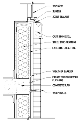
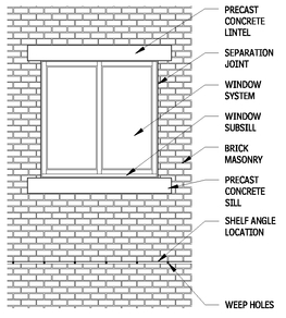
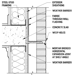
An investigation was performed to determine the causes of masonry distress and water leakage observed on a midrise building constructed in the 1990s in the northern United States. The exterior walls consisted principally of cavity wall construction with brick masonry cladding backed up by cold-formed metal framing. The steel studs were covered with exterior gypsum sheathing with a building paper weather barrier. A drainage cavity existed between the brick veneer and the building paper, with the weight of the brick supported by the foundation and by shelf angles at floor slabs. Precast concrete lintels and sills occurred at all windows. In this system, water that penetrated the brick veneer was intended to flow down within the drainage cavity behind the masonry to flashings installed at the shelf angles and lintels, and drain to the exterior through weep installed on the flexible flashing.
As in the design process, historical research demands an ongoing critique of the sources.
• Correctness: Is a source possibly false or biased toward or against the subject?
• Provenance: Where did the source come from, and is it reliable?
• Time: What is the date of the source and how does that relate to the subject?
• Origin: Who was the author of the source?
• Originality: Is the source or the information in it original form?
The sources also need to be ordered, of which several ways exist:
• Elementary information: Order the material according to time, place, subject, author, or any combination.
• Thematic organization: This orders the information according to type, based on function use or form or based on material and construction, for example.
The literature, too, needs to be ordered in a way that is useful. The ways of doing so include:
• Topographical ordering: Material is ordered according to published descriptive lists and inventories.
• Chronological ordering: Literature is sorted according to the era or date it was produced.
• Bibliographical ordering: The lists of books and other bibliographical materials dictate the way the information is organized.
• Monographic ordering: Material is ordered according to specific projects or people.
In terms of a building itself, the analysis of it takes two forms:
• Morphological analysis: This involves looking at the specific characteristics (what and how) of the work in order to compare it to others and to put it in a broader perspective (why). This can include the formal, functional, and structural aspects of the work, or its stylistic or conceptual aspects.
• Technical analysis: This can include looking at the site or material of a building or the construction methods used in it.
Evaluating the physical fabric of a historic building, says Barry Richardson in
Defects and Deterioration in Buildings (Spon, 2001)
, involves its own particular investigative process that involves the following tools:
• Moisture meter to assess moisture content of wood and other materials and assemblies
• Borescope and a small mirror to look into inaccessible or hard-to-see places
• Utility knife, claw hammer, crowbar, chisel, screwdrivers, saw, and electric drill
• Camera, plastic sealable bags or sealable envelopes for samples
• Sectional ladder, flashlight, notebook, waterproof pens or pencils
Research into the history and conditions of existing structures constitutes one of the largest areas of architectural research because of the widespread reuse of buildings. The following case study, by Harry Hunderman and Richard Weber of Wiss, Janney, Elstner Associates, offers some insight into how this is done.
The windows consisted of a thermally improved, aluminum-framed system, with fixed insulating glass (IG) units. The window assembly typically had two IG units with an intermediate vertical mullion and a thermally improved aluminum subsill, with end dams extending beneath the full length of the window. Aluminum and glass curtain walls extending several stories in height also interrupted the brick masonry cladding at several areas.
TYPICAL OVERALL WALL SECTION AT WINDOW AND SHELF ANGLE
15.1
INVESTIGATION
Problems observed in the exterior cladding included outward displacement (bulging) and cracking of the masonry and water leakage into the interior at various locations. The purpose of the investigation was to determine the causes of distress and leakage, evaluate the extent of the problems, and provide direction for repairs.
REVIEW OF DOCUMENTS
Prior to the field investigation, original architectural and structural documents were reviewed, as well as shop drawings and submittals from original construction. In addition, the review of maintenance records helped to understand the nature of existing construction and past problems and repairs.
VISUAL SURVEY
Following review of available documents, a visual survey of the building exterior walls was performed from grade, using binoculars and from the roof areas. This visual survey provided a general understanding of existing conditions and permitted the investigators to select the range and extent of further investigation required.
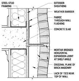
The visual survey of the brick veneer revealed numerous bond separations between masonry units and mortar. The extent of bond separations also suggested poor workmanship and tooling of the mortar joints during installation. These separations, as well as cracks and voids in the mortar, allowed an increased amount of water to enter into the drainage cavity behind the masonry. Efflorescence, observed on the brick masonry at several isolated locations, primarily above the shelf angles, results from the deposition of soluble salts on the masonry surface and usually indicates water moving through the masonry. In addition, cracking and bulging were observed at shelf angle locations, and control joints had completely compressed in areas where there appeared to be blockage of the horizontal control joint.
TYPICAL WALL ELEVATION AT WINDOW AND SHELF ANGLE
15.2
SECTION THROUGH SHELF ANGLE AS ORIGINALLY CONSTRUCTED
15.3
Visual observation also revealed a widespread failure of sealant joints at window perimeters and curtain walls, including both adhesive and cohesive failures. A visual survey of the interior, performed in conjunction with the exterior survey, showed water damage to interior finishes at numerous windows, primarily at the ends of the sill member. Based on the results of the visual survey, locations were selected for close-up inspection, inspection openings, and water leakage testing.
CLOSE - UP INSPECTION
A close-up inspection was performed at representative locations from suspended scaffolding (swing stages) and personnel lifts. The close-up inspection provided the opportunity for inspection openings, field-testing, removal of samples, and implementation of a variety of diagnostic techniques. Evaluating the precast concrete units demanded nondestructive test methods, which included sounding techniques (tapping with a hammer) to identify delaminations and voids, and a metal detector survey to identify the presence and general location of metal elements. A borescope, which uses a fiberoptic light source, was used to examine concealed conditions within the masonry wall through very small openings made in mortar joints. Sample removals included brick and mortar for laboratory testing, as discussed later in this section. During the metal detector survey for embedded brick ties, a lack of brick ties was detected near the floor lines. This allowed the masonry to displace outward at the shelf angles.
SECTION THROUGH SHELF ANGLE SHOWING BULGING
15.4
Inspection openings were performed at selected locations to permit examination of concealed conditions and to verify as-built construction. Inspection openings were made in the brick veneer at suspected sources of leakage and observed distress and at other locations of interest to expose the underlying construction to view. For example, inspection openings made at the shelf angle locations revealed that the through-wall flashing at the shelf angles consisted of paper-coated copper. The laminated sheet flashing was terminated at or behind the toe of the angle, rather than extending to the face of the masonry. The flashing was not sealed down to the steel angle. Because the flashing terminated at the edge of the steel and was not sealed down, any water flowing off the end of the flashing could contact the steel angle.
As another example of conditions revealed at inspection openings, the flashing at the window heads was found not to extend beyond the precast concrete lintel. Instead, flashing at these locations terminated approximately 2 in. beyond the window opening without end dams. Water collected by this flashing flowed laterally and would drop onto the top of the masonry at the jamb, as observed during testing.
WATER LEAKAGE TESTING
A visual survey on the building interior was completed to identify evidence of moisture infiltration. Water spray testing was performed at selected exterior locations to evaluate the resistance of wall construction and windows to water leakage. Four test methods were used.
In spray rack testing, water is introduced against the surface of the masonry with a rack of nozzles calibrated to deliver water at a rate of 5 gallons per square foot per hour. The spray rack was built and calibrated in accordance with ASTM E 1105, “Standard Test Method for Field Determination of Water Penetration for Installed Windows, Curtain Walls, and Doors by Uniform or Cyclic Static Pressure Difference.” The test was performed without an applied air pressure difference across the wall system. In water permeance testing, a 3-ft-wide by 4-ft-high chamber is mounted on the masonry surface. Water is applied as a sheet across the specimen within the chamber while air pressure is also applied. This test was performed in accordance with ASTM C 1601, “Standard Test Method for Field Determination of Water Penetration of Masonry Wall Surfaces.” The test determines the rate water penetrates the masonry during heavy, wind-driven rain conditions. The amount of water flowing into the masonry, rather than being circulated by the chamber and supply tank, is measured as the amount of water penetration into the wall. The tests were run for a period of four hours each at an applied air pressure of 10 psf across the exterior of the test area.
In wall drainage testing, water is applied through plastic tubing directly into the drainage cavity behind the brick veneer to evaluate the performance of the wall drainage system and its effectiveness in handling water that penetrates into the wall system. As specified in the American Architectural Manufacturers Association (AAMA) test method 501.2, “Quality Assurance and Diagnostic Water Leakage Field Check of Installed Storefronts, Curtain Walls, and Sloped Glazing Systems,” a calibrated hand-held nozzle is used to test the resistance of nonmoving joints to water penetration and to help isolate, or pinpoint, sources of water leakage.
Prior to performing water infiltration testing, finishes were removed to allow monitoring for leakage. This included the removal of the interior stool and gypsum board at leakage locations and surrounding windows to be tested. In this fashion, leakage occurring during testing could be readily observed and the sources pinpointed.
Water permeance testing was performed at two areas where the condition of the masonry was judged visually to be relatively good and exhibited few bond separations. The results of the testing indicated that the brick masonry had a relatively high permeance for a building of this age. The high permeance results in an increased amount of water that must be handled and drained by the wall flashing system, especially during heavy, wind-driven rains.
During testing of the through-wall flashing at the shelf angle, water leakage occurred at the intersection of the shelf angle and the curtain wall system. Water flowed onto the interior finishes and ran down the interior of the curtain wall frame. Water leakage also occurred at the underside of the concrete slab. This leakage occurred near splices in the shelf angles.
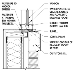
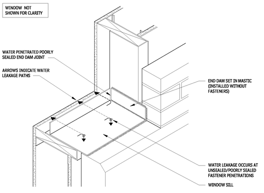
During testing of the masonry, water flowed behind the masonry at the window jamb and bypassed the window subsill/masonry intersection and flowed onto the interior sill framing. Water was directed into the subsill in many cases; however, at some locations, leakage occurred onto the wood blocking at the sill due to defects in the subsill end dam or poorly sealed joints between the end dam and the adjacent rough opening materials.
TYPICAL WINDOWSILL DETAIL
15.5
FLASHING AND END DAM LEAKAGE
15.6
During spray rack testing of the window system, water leakage readily occurred at the subsill. At locations where nozzle testing was performed to pinpoint leak locations, observation from the interior during the testing indicated that the leakage at the sill of the test windows was the result of water penetration at the subsill, particularly at fastener penetrations and at incompletely sealed end dams.
Because of the need to confirm paths of water movement at the windowsill, the window system was disassembled at several representative locations. The subsill was found to be fastened to the wood blocking below, with screws that penetrate the subsill; however, joint sealant was not present at some of these screw penetrations. Aluminum end dams were present at the terminations in the subsill; however, the seals between the end dams and the subsill were not complete in all areas.The end dams were not mechanically fastened to the subsill. Also, subsill fasteners penetrated the horizontal legs of the end dams at a number of locations.
Subsequently, laboratory testing of selected materials was performed to provide specific information about materials characteristics and causes of failure. For example, petrographic examination was performed on samples of precast concrete to confirm that no compositional problems appeared to be present. Petrographic studies involved a standardized microscopic examination of materials samples based on the methods outlined in ASTM C 856, “Petrographic Examination of Hardened Concrete,” to evaluate the overall quality and soundness of the materials. Compositional analysis of the mortar using methods of ASTM C 1324, “Standard Test Method for Examination and Analysis of Hardened Masonry Mortar,” including chemical methods to supplement petrographic examination, was performed to confirm that the mortar composition was in accordance with specification requirements. Absorption and saturation coefficient testing of brick was performed in accordance with ASTM C 216, “Standard Specification for Facing Brick (Solid Masonry Units Made from Clay or Shale).” Per ASTM C 216, five bricks were included in each test, and half of each brick was used as a test specimen. The results were obtained for the individual specimens and averages calculated, to compare the brick to requirements of ASTM C 216 performance. The information gathered through research and investigation was analyzed to determine the causes of observed distress and to inform decision making about appropriate repairs.
Contributors:
Harry Hunderman and Richard Weber, Wiss, Janney, Elstner Associates, Inc., Northbrook, Illinois.
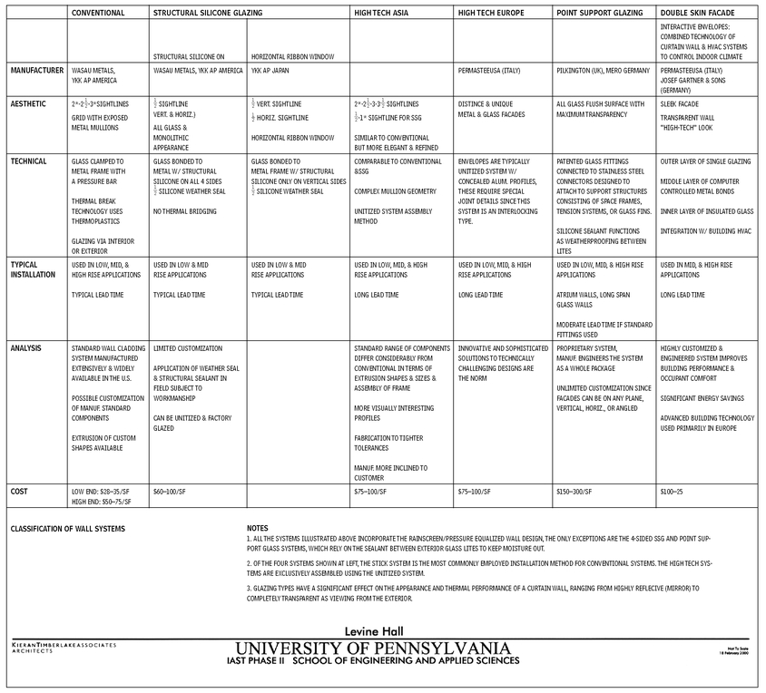
CURTAIN WALL TYPES
15.7
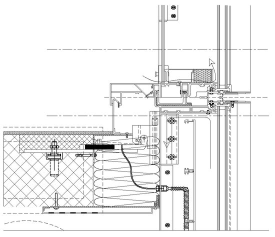
Contributor:
KieranTimberlake Associates LLP, Philadelphia, Pennsylvania.
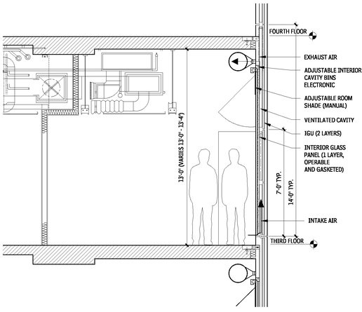
ACTIVE CURTAIN WALL SECTION
15.8
GLAZING DETAIL
15.9
