Chapter 2

3D Printing and Nanomanufacturing

JinGyu Ock2,*
Xuanyi Ma1,*
Wei Li2
Shaochen Chen1
1    Department of NanoEngineering, University of California, San Diego, La Jolla, CA, USA
2    Department of Mechanical Engineering, University of Texas, Austin, TX, USA
*    These authors contributed equally

Abstract

The rapid development of 3D printing and nanomanufacturing techniques has attracted tremendous attention within the field of bioengineering, in particular biomaterials and tissue engineering. Typical 3D printing and nanomanufacturing techniques use laser or UV light to fabricate 3D objects in a point-by-point or layer-by-layer fashion corresponding to 3D computer-aided design models. In this chapter, we give an overview of the existing 3D printing and nanomanufacturing techniques, particularly laser-assisted direct writing techniques and stereolithography systems. We describe the basic setups and processing principles of each system. We also introduce a variety of biomaterials, including their properties, applications, and the processing by the previously mentioned manufacturing systems. Furthermore, we emphasize the application of these 3D printing and nanomanufacturing techniques in the field of biomedical engineering with detailed examples of the state-of-the-art research that has been done worldwide. The cell lines, design guidelines, and parameters are reviewed as well.

Keywords

3D printing
additive manufacturing
nanomanufacturing
regenerative medicine
scaffold
tissue engineering

2.1. Introduction

Driven by the goal of creating biomimetic microenvironments that manifest natural tissue structures and compositions, developing three-dimensional (3D) constructs that incorporate (a) sophisticated patterning of extracellular matrix (ECM) components, (b) biomolecules, and (c) even cells has been a main research focus for studying biological problems and engineering tissues (Griffith, 2002; Orban et al., 2002; Sharma and Elisseeff, 2004). However, conventional fabrication methods used for manufacturing 3D scaffolds, such as electrospinning (Zong et al., 2005), fiber deposition (Moroni et al., 2006), freeze-drying (O’Brien et al., 2004), gas foaming (Yang et al., 2001; Nazarov et al., 2004), salt leaching (Roy et al., 2003), and porogen melting (Lin et al., 2003), do not allow precise control of the internal structural features and topology. In addition, many of the current 3D scaffolding systems are only capable of achieving either a bulk incorporation of biomolecules within the scaffolding matrix or an exogenous delivery of necessary chemicals, hormones, or growth factors through culture medium (Richardson et al., 2001; Johnstone et al., 1998; Nuttelman et al., 2004). An important step toward achieving the goal of creating precise, spatially patterned 3D microenvironments within a single scaffold for tissue engineering applications is the development of novel scaffold manufacturing techniques by which distributed environmental factors can be incorporated together in a simple yet precise and consistent fashion.
3D printing and nanomanufacturing, in particular laser-assisted direct writing techniques and stereolithography, are capable of efficiently fabricating complex 3D scaffolds with precise microarchitecture to achieve that step (Han et al., 2008; Lu et al., 2006; Mapili et al., 2005). Such fabrication systems provide the possibilities of incorporating cells inside the scaffold walls during fabrication of 3D constructs or seeding cells on the already patterned scaffolding surface. As a promising approach to develop user-defined precise 3D microenvironments with complex biological components, 3D printing has been used in a variety of applications ranging from tissue engineering scaffolding to cancer cell migration study and neural stem cell culture, with the potential of patterning multiple cell types in precise 3D locations.

2.2. 3D Printing and Nanomanufacturing Techniques

With the development of computer-aided design (CAD) technology and automation techniques, rapid and automatic additive manufacturing (AM) systems have advanced for the fabrication of complicated 3D structures over the past few decades. In general, the 3D model to be fabricated is first designed using CAD modeling software, such as Solidworks and AutoCAD. Generated 3D CAD data are then processed and sliced into layers of equal thickness, each of which is the cross-section of the 3D model at a certain level. Sliced data are imported into the AM system to fabricate 3D objects layer-by-layer. In this fabrication process, layers are cumulated vertically and fused to form the final physical object (Chua et al., 2010; Tan et al., 2005).

2.2.1. Selective Laser Sintering

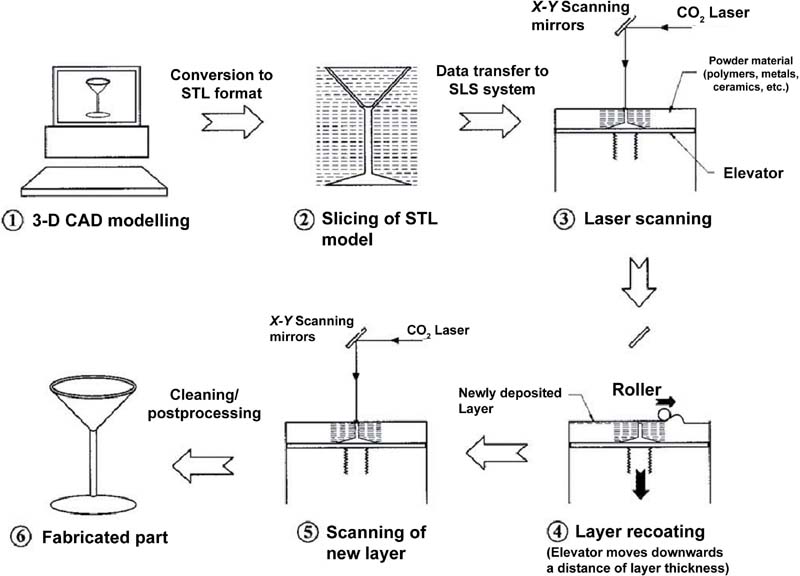
Selective laser sintering (SLS) (Tan et al., 2005; Duan et al., 2010; Kanczler et al., 2009; Liu et al., 2013; Williams et al., 2005) was developed and patented in the mid-1980s (Deckard, 1989). This technique uses a laser beam (usually CO2 laser) to sinter slices of powdered materials via repeated process of spreading layers and selectively heating and fusing each powdered layer in order to fabricate three-dimensional structures. Thus, the objects are formed layer-by-layer from sliced CAD data. During the process, the unmelted powders act as the support for the fused object. Figure 2.1 represents the selective laser sintering process.
image
Figure 2.1 A schematic layout of the SLS process (Tan et al., 2005).

2.2.2. Laser-Guided Direct Writing

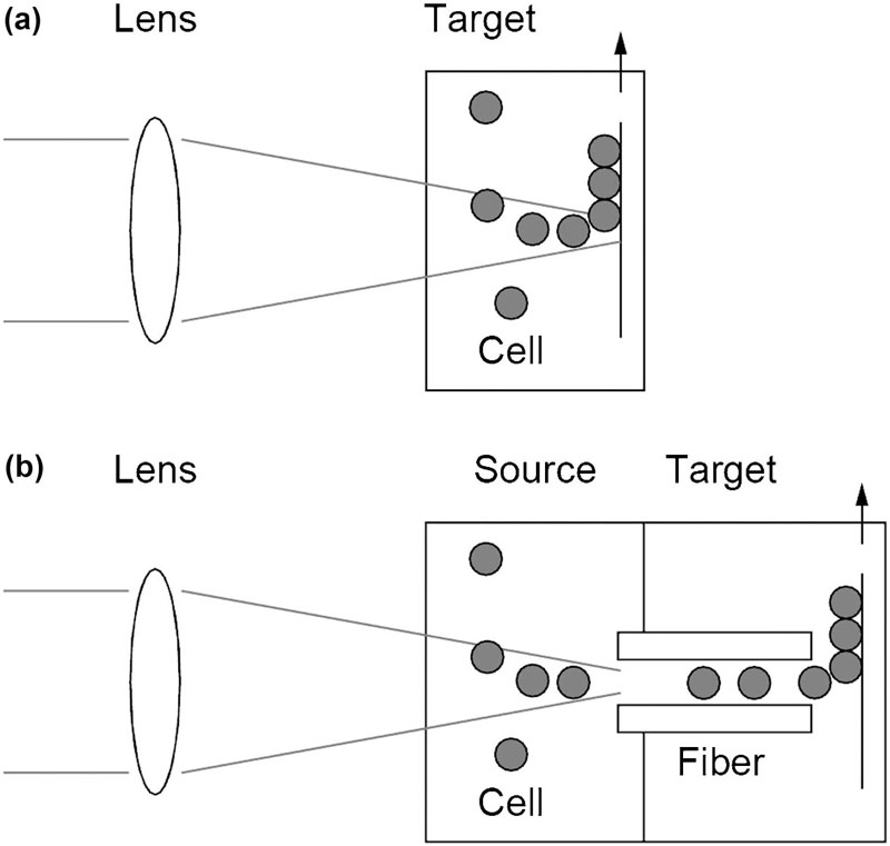
The laser-guided direct writing (LGDW) (Odde and Renn, 2000; Nahmias et al., 2005; Nahmias and Odde, 2006; Narasimhan et al., 2004; Rosenbalm et al., 2006) technique was first used for micropatterning of embryonic-chick spinal-cord cells (Odde and Renn, 1999). The driving force of the LGDW method arises from the scattering of laser light by microparticles or cells. In contrast to the high-numerical-aperture lens used in optical trapping systems, the LGDW system uses a low-numerical-aperture lens so as to provide an axial propelling force to the particle instead of trapping it in the vicinity of the focal point. Once a particle or cell interacts with the laser, it is drawn to the center of the beam where the intensity is maximal and simultaneously pushed along the axial direction of the laser beam by radiation pressure. The guided object is deposited on a target surface, which is placed vertically at a certain point along the optical axis. By moving the target surface relative to the laser beam, three dimensional patterns of particles can be drawn on the target surface. The basic concept of cell deposition of LGDW method is illustrated in Figure 2.2.
image
Figure 2.2 Laser-guided direct writing system. (a) Laser light is focused weakly into a suspension of particles. The particles are propelled by the light through the fluid and deposited on a target surface. Moving the target relative to the laser beam results in a line of particles being drawn. (b) Light is coupled into a hollow optical fiber and particles are carried through the fiber to the target surface. The process can be observed in real time by optical microscopy (Odde and Renn, 1999).

2.2.3. Laser-Induced Forward Transfer
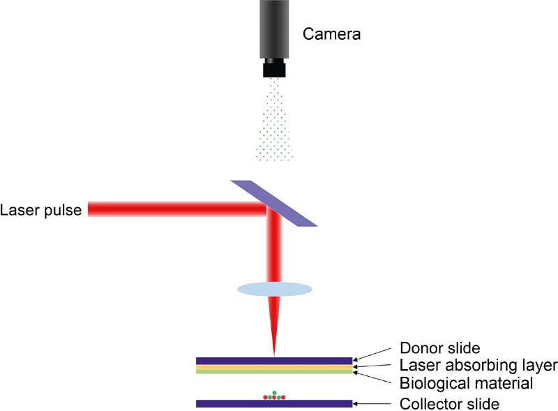
Laser-induced forward transfer (LIFT) (Koch et al., 2009, 2012; Gruene et al., 2010) mainly employs a high-powered pulse laser and two coplanar glass slides. The experimental setup is described in Figure 2.3. The upper slide, called “donor-slide”, is coated with an energy absorption metal layer and a layer of material containing cells. Laser pulses are focused on the metal layer via the glass slide, evaporating the laser absorbing layer locally. During the process, the laser pulse generates a high gas pressure that transfers the underlying cell compound toward the lower slide, referred to as “collector-slide.” The biological materials containing cells are usually a culture medium or hydrogel that provides a humid environment, thus preventing cell dehydration. Hydrogel has the additional function of sustaining cell structure.
image
Figure 2.3 A schematic of LIFT (Gruene et al., 2010; Koch et al., 2012; Ringeisen et al., 2004).

2.2.4. Matrix-Assisted Pulsed Laser Evaporation Direct Writing

The setup of matrix-assisted pulsed laser evaporation direct writing (MAPLE DW) (Ringeisen et al., 2004; Patz et al., 2006; Doraiswamy et al., 2007) is similar to the LIFT system shown in Figure 2.3. Instead of using a glass slide for the “donor-slide,” MAPLE DW employs an optically transparent quartz support called “ribbon.” The ribbon is coated with biological materials, such as Matrigel® or bioceramic. The biomaterials with cells are referred to as “matrix”. The substrate, similar to the “collector-slide”, may or may not be covered with hydrogel. Laser is focused on the interface of the quartz support and a laser-absorptive layer containing cells. The laser beam causes evaporation of part of the biomaterial layer, which generates gas bubbles locally. The gas bubbles result in the release and propulsion of the cell-seeded matrix to the receiving substrate.

2.2.5. Biological Laser Printing

Biological laser printing (BioLP) was developed by Barron et al. (Barron et al., 2004, 2005; Pirlo et al., 2012; Othon et al., 2008). It is similar to the previous two processes, LIFT and MAPLE DW, illustrated in Figure 2.3. BioLP utilizes an optically transparent quartz instead of the glass slide used in LIFT. Metal or metal oxide is coated on the quartz support as the laser absorption layer. The biomaterial layer with cells, such as powder, liquid, or gel, is coated on the laser-absorbing layer. The incident laser energy is focused and absorbed at the interface of the quartz support and laser absorption layer. The heat generated by the laser absorption layer causes vaporization of water in the biomaterial. The biomaterial is then transferred from the ribbon surface to the receiving substrate surface. Thus, this technique reduces potential damage to biological materials.

2.2.6. Stereolithography Techniques

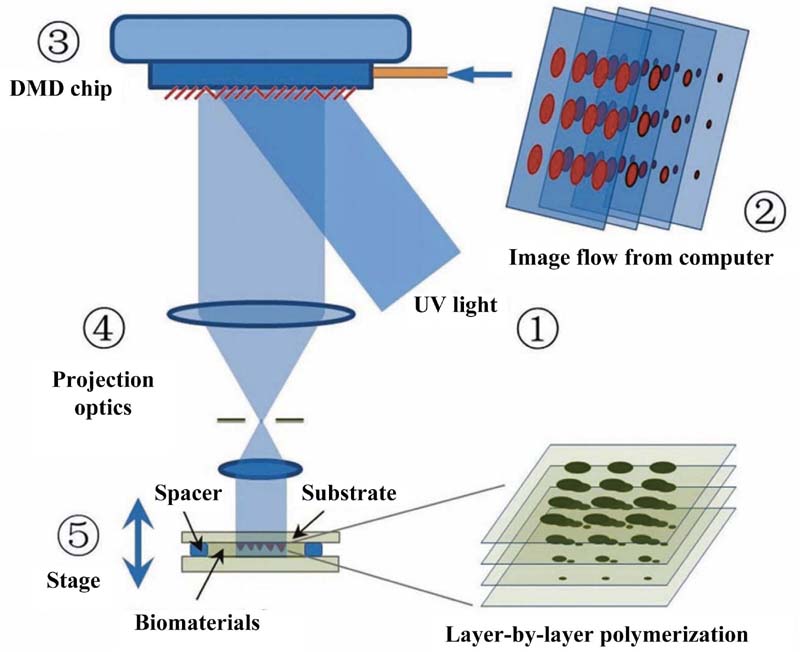
The stereolithography (STL) technique was developed by Hull in 1986 and was described in his patent “Apparatus for Production of Three-Dimensional Objects by Stereolithography” (Hull, 1986). Stereolithography is a technique of producing parts one layer at a time by curing a photoreactive resin with a UV laser or another similar power source. In addition to using a single-point laser, stereolithography can be performed with a digital micromirror-array device (DMD) (Suri et al., 2011; Gauvin et al., 2012; Soman et al., 2012, 2013; Lin et al., 2012). The DMD is an array of up to several millions of microsized mirrors that can be controlled independently to on and off state (Melchels et al., 2010). In this approach, the structure is not created via point-by-point scanning, but in a layer-wise fashion by curing the entire layer simultaneously. After one layer is fabricated, the platform is lowered or raised to cumulate a new layer. The thickness of each layer is controlled by the distance between the surface of the platform and the liquid resin surface. Based on the basic concept just mentioned, Zhang et al. developed a dynamic optical projection stereolithography (DOPsL) system for the rapid fabrication of complex 3D extracellular scaffolds (Zhang et al., 2012). The setup of the DOPsL system is shown in Figure 2.4. Since this DMD-based stereolithography technology simultaneously utilizes a million micromirrors rather than one single focused point, the DOPsL system offers superior processing speed compared to other nanofabrication techniques, thus making it more suitable for manufacturing large structures with complex details with a submicron resolution (Zhang et al., 2012). With many advantages, including rapid fabrication speed, maskless, flexibility, and relatively high resolution, the DOPsL system is an appealing platform for the manufacture of complex 3D designer scaffolds for in vitro tissue engineering as well as functional cellular constructs for in vivo implantation (Zhang et al., 2012).
image
Figure 2.4 Schematic setup of the DOPsL system (Zhang et al., 2012).
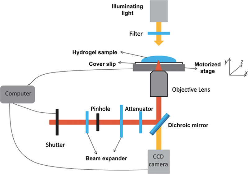
A special laser directing technique is two-photon polymerization (2PP) (Zhang and Chen, 2011; Zhang et al., 2013; Ovsianikov et al., 2011a, 2011b; Gebinoga et al., 2013), which has been used to produce nanoscale features due to its high fidelity and resolution. 2PP systems usually utilize a femtosecond laser to induce two-photon absorption (2PA). 2PA is a process by which one molecule is excited to a higher energy electronic state by the simultaneous absorption of two photons (Zhang and Chen, 2011). 2PA was described theoretically in 1931 by Goeppert-Mayer (Göppert-Mayer, 1931) and first demonstrated experimentally in 1961 by Kaiser and Garrett (Kaiser and Garrett, 1961) in a CaF2:Eu2+ crystal, and in 1962 by Abella in caesium vapor (Abella, 1962). Figure 2.5 shows a schematic of a typical 2PP fabrication system (Zhang and Chen, 2011). The laser used in the system is a Ti:sapphire femtosecond laser (100-fs pulses at a repetition rate of 80 MHz and wavelength of 800 nm). The laser beam is expanded and guided by a group of mirrors into an inverted microscope. It is then focused by an oil-immersion objective lens onto the sample that is mounted on a motorized stage with high resolution (< 20 nm), which moves three-dimensionally to draw a defined 3D nanostructure in the sample. The 3D structure is first designed in AutoCAD and then imported to the software of the motorized stage, which controls the motion of the stage in xyz directions. A CCD camera is used to monitor the fabrication process. The laser power can be continuously adjusted by an attenuator. With this femtosecond laser fabrication system, Zhang et al. were able to fabricate defined and complex 3D structures with a resolution of 100 nm (Zhang and Chen, 2011).
image
Figure 2.5 Schematic setup of a TPP fabrication system (Zhang and Chen, 2011).

2.2.7. Classification of Additive Biomanufacturing Techniques
Based on their working principles, the existing AM systems can mainly be categorized into three groups: (1) powder-fusion-based techniques, such as SLS; (2) particle- or cell-deposition-based techniques, such as LGDW, LIFT, and MAPLE DW; and (3) photo-polymerization-based techniques, such as stereolithography and 2PP (Duan and Wang, 2013).
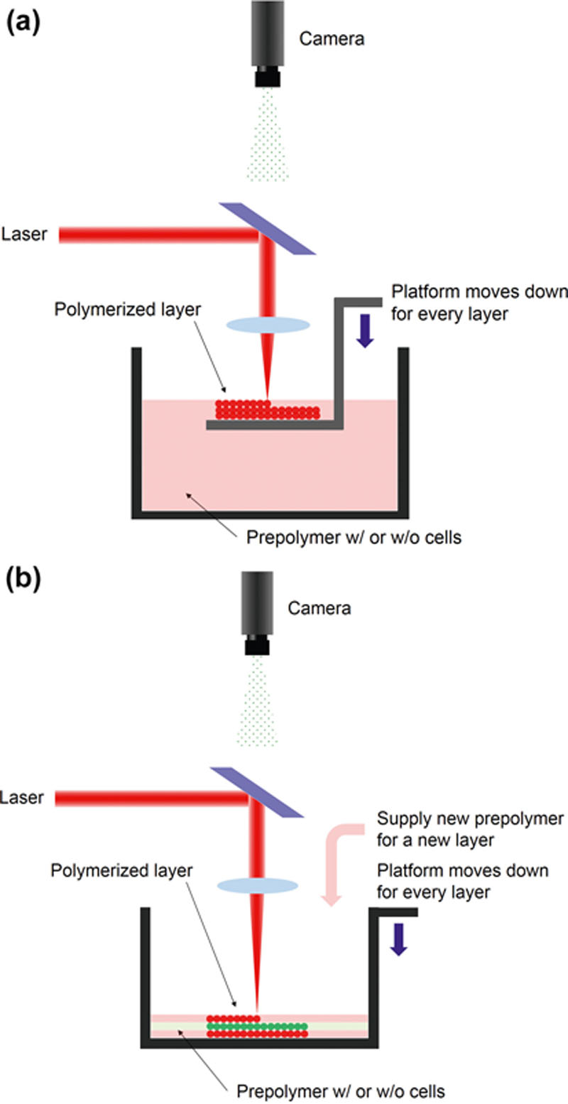
These additive manufacturing techniques can also be categorized based on their process configurations: top–down and bottom–up. Most forms of laser-assisted additive manufacturing, such as SLS, LG DW, LIFT, MAPLE DW, and BioLP, are classified as bottom–up approaches. The accumulation starts from the bottom of the platform and prepolymer materials are supplied for each layer. This approach has the advantage of fabricating multiple layers with different materials in each layer (Mapili et al., 2005; Nahmias et al., 2005; Odde and Renn, 1999; Koch et al., 2009, 2012; Pirlo et al., 2006; Ovsianikov et al., 2010; Chan et al., 2010). SLA employs both top–bottom and bottom–up approaches, as shown in Figure 2.6. The top–down configuration consists of a container and a movable platform that is located in the container. The platform is immersed just below the surface of a prepolymer solution. The laser beam is focused onto the surface (xy plane) of liquid resin to polymerize the resin. Once a layer is photo-polymerized, the platform is lowered by a specific distance to fabricate a new layer. In the bottom–up approach, the container is a movable platform on which a polymerized resin layer is created. Liquid prepolymer is supplied into the container for one layer from the bottom to the top. Table 2.1 lists the type of approach that each technique belongs to.
image
Figure 2.6 A schematic representation of SLA: (a) top–down approach, (b) bottom–up approach.

2.3. Biomaterials Used with Additive Biomanufacturing Techniques

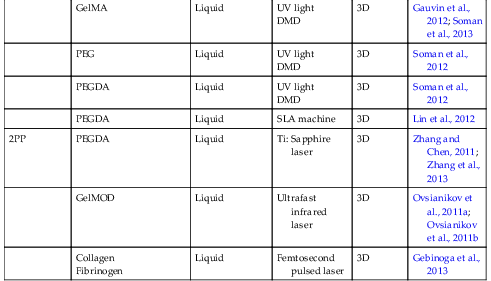
Over the past two decades, various biocompatible or biodegradable materials, including polymeric materials (Puppi et al., 2010; Nair and Laurencin, 2007), bioceramics (Best et al., 2008), and hydrogels (Fedorovich et al., 2007), have been employed and developed for use with laser-based additive biomanfacturing techniques in bioapplications, such as drug delivery, regenerative medicine, and tissue engineering. In this section, we briefly review typical biomaterials that have been used with laser-based additive biomanufacturing techniques. Table 2.2 provides a summary of the biomanufacturing techniques listed with corresponding biomaterials used.

Table 2.2

Additive manufacturing technique using laser

Fabrication techniqueUnit elementPolymer typeLaser typeDimensionReferences
SLSPEEK, PVA, PCL, PLLA, HAPowderCO2 laser3DTan et al., 2005
Ca-P/PHBV CHA/PLLA
Powder
(nanocomposite)
CO2 laser3DDuan et al., 2010
PLA + Carbon BlackPowderFiber diode laser3DKanczler et al., 2009
TitaniumPowderNd:YAG laser3DLiu et al., 2013
PCLPowderCO2 laser3DWilliams et al., 2005
LGDWLaser guided cellUnit cellDiode laser3DOdde and Renn, 2000; Nahmias et al., 2005; Nahmias and Odde, 2006
Laser guided cellUnit cellTi: Sapphire laser2DNarasimhan et al., 2004; Rosenbalm et al., 2006
LIFTAlginate + NaClGel-type layerNd:YAG laser3DKoch et al., 2009; Gruene et al., 2010; Koch et al., 2012
MAPLEDWMatrigel®Gel-type layerArF excimer laser3DRingeisen et al., 2004; Patz et al., 2006
Hydroxyapatite and zirconia / glycerol-water solutionSolution layerArF excimer laser3DDoraiswamy et al., 2007
BioLPProtein/ cell solution with glycerolSolution layerNd:YAG laser3DBarron et al., 2004; Barron et al., 2004
Cell solution with glycerolSolution layerMultigas excimer laser2DBarron et al., 2005
Cell solution with methyl-celluloseSolution layerNd:YAG laser3DOthon et al., 2008
SLA - laserPEGDMALiquidNd:YAG laser3DMapili et al., 2005
PEGDALiquidHeCd laser3DChan et al., 2010; Chan et al., 2012
PPF/ DEFLiquidNd:YVO4 laser3DLee et al., 2007
SLA - DMDGMHALiquid
UV light
DMD
3DSuri et al., 2011
GelMALiquid
UV light
DMD
3DGauvin et al., 2012; Soman et al., 2013
PEGLiquid
UV light
DMD
3DSoman et al., 2012
PEGDALiquid
UV light
DMD
3DSoman et al., 2012
PEGDALiquidSLA machine3DLin et al., 2012
2PPPEGDALiquidTi: Sapphire laser3DZhang and Chen, 2011; Zhang et al., 2013
GelMODLiquidUltrafast infrared laser3DOvsianikov et al., 2011a; Ovsianikov et al., 2011b
Collagen
Fibrinogen
LiquidFemtosecond pulsed laser3DGebinoga et al., 2013


2.3.1. Powder-Type Materials

Selective laser sintering has been used with powdered materials—mostly synthetic polymers, polymer composites, or ceramics—to fabricate 3D solid structures. These materials include PEEK, PVA, PCL, PLLA, and HA (Tan et al., 2005; Duan et al., 2010; Kanczler et al., 2009). Polyetheretherketone (PEEK) is a bio-inert polymer with a melting point of 343 °C and a glass temperature of 143 °C. These properties make the polymer stable to be processed at high temperatures; therefore, PEEK is easily sterilized in autoclave or by radiation without sacrificing its materials. Poly (vinyl alcohol) (PVA) is a semicrystalline polymer and copolymer of vinyl alcohol and vinyl acetate. PVA has a melting point of 220–240 °C and a glass transition temperature of 58–85 °C (Tan et al., 2005). Polycaprolactone (PCL) is also a semicrystalline polyester with a melting point of 55–60 °C and a glass transition temperature of −60 °C. It could be hydrolytically degraded due to the presence of hydrolytically labile aliphatic ester linkages. The degradation rate is about 2–3 years (Nair and Laurencin, 2007). Poly (L-lactic) acid (PLLA) has a melting point of 172.2–186.8 °C and a glass transition temperature of 60.5 °C (Tan et al., 2005). The mineral component of bone is calcium phosphate. Hydroxyapatite (HA) is one of the synthetic calcium phosphate ceramics. The bioceramic is widely used because it is chemically similar to the inorganic component of hard tissues. HA theoretically consists of 39.68 wt% Ca and 18.45 wt% P. It is more stable compared to other calcium phosphate ceramics within a pH range of 4.2–8.0 (Best et al., 2008).
Nanocomposites of bioceramic and biodegradable polymer are often sintered to facilitate proliferation of and alkaline phosphatase activity expression by human osteoblast-like cells (SaOS-2). Poly (hydroxybutyrate) (PHB) is a naturally occurring polyester by bacteria. The polymer has a melting point of 160–180 °C. The copolymer of PHB and hydroxyvalerate is poly (hydroxybutyrate-co-hydroxyvalerate) (PHBV), which is a semicrystalline polymer with a melting temperature lower than PHB. The glass transition temperature of PHBV is in the range of −5–20°C (Nair and Laurencin, 2007). Calcium phosphate (Ca-P)/PHBV and carbonated hydroxyapatite (CHA)/ PLLA nanocomposites have been employed to fabricate tissue engineering scaffolds (Duan et al., 2010). In addition, titanium powder has been sintered to form bone scaffolds (Liu et al., 2013).

2.3.2. Gel-Based Biomaterials

Gel-based biomaterials are widely used in additive biomanufacturing processes. Collagen gel or Matrigel® is coated on the substrate to help cells adhere to the substrate; for three-dimensional patterning, Matrigel® is layered on top of the first pattern in the LGDW method (Odde and Renn, 2000; Nahmias et al., 2005; Nahmias and Odde, 2006; Narasimhan et al., 2004; Rosenbalm et al., 2006). Alginate hydrogel is used in the LIFT method to encapsulate cells (Koch et al., 2009, 2012; Gruene et al., 2010). MAPLEDW transfers biomaterials containing cells from transparent quartz support to a receiving substrate. Matrigel® was used as the cell-containing matrix and laser absorptive layer (Ringeisen et al., 2004; Patz et al., 2006). Bioceramic ribbon is also used by solvating hydroxyapatite and zirconia powders in glycerol/water matrices and spin coating this solution (Doraiswamy et al., 2007). BioLP is an improved version of MAPLEDW, since it employs quartz support coated by a metal or metal oxide, which eliminates the direct interaction of laser and biomaterials. A ribbon consists of three layers, optical transparent quartz, metal or metal oxide laser absorptive layer, and cell solution having cells, cell culture medium, and glycerol or methyl-cellulose. Glycerol and methyl-cellulose were used to reduce evaporation of biological materials. Cell solution was transferred onto substrate coated by Matrigel® (Barron et al., 2004, 2005; Pirlo et al., 2012; Othon et al., 2008).
The types of hydrogels utilized for structure fabrication using light-assisted bioprinting include, but are not limited to, poly(ethylene glycol) diacrylate (PEGDA), poly(ethylene glycol) dimethacrylate (PEGDMA), methacrylamide-modified gelatin (GelMOD), gelatin methacrylate (GelMA), and glycidyl methacrylate modified hyaluronic acid (GMHA). Among these, PEGDA, GelMA, and GMHA are the most extensively used (Hribar et al., 2014).
PEGDA hydrogels, with their superior biocompatibility, high water retention ability, and tunable mechanical properties, in particular stiffness retention, serve as excellent candidates for synthetic biomaterials for biomedical applications (Baroli, 2007). The cross-linking extents and thus the material properties (e.g. stiffness, porosity, and osmotic swelling) of polymerized PEGDA hydrogel can be customized by varying the molecular weight of the monomer (typically 700–10000 Da) as well as the fabrication parameters (e.g. exposure time and laser intensity) (Hudalla et al., 2008). PEGDA hydrogels are generally nondegradable and nonbioactive. Nevertheless, such properties can be enhanced by chemical modification, mixing with other degradable materials, or incorporation of adhesive peptide sequence like the tetrapeptide Arg–Gly–Asp–Ser (RGDS) or proteins like laminin (Hribar et al., 2014). GelMA hydrogels, made from xenogenic-modified monomers, belong to the type of naturally derived hydrogels and are bioactive for their peptide sequences, which allow the binding of integrin protein expressed on cell membrane (Hribar et al., 2014). Like most gelatin-based hydrogels, GelMA hydrogels provide high water content and modifiable properties (e.g. swelling and stiffness) based on monomer percentage. GMHA hydrogels, another naturally derived hydrogels from native ECM component, possess superior biocompatibility and are in general nonimmunogenic like natural hyaluronic acid (Gauvin et al., 2012). Although a certain level of bioactivity has been demonstrated, the surfaces of GMHA scaffold are ready for further modification to incorporate more cell-adhesive proteins like laminin (Hribar et al., 2014).
Laser-based stereolithography (SLA) patterns photocrosslinkable hydrogels or polyesters to create a microenvironment in 3D structure using UV laser. The technology was applied to PEGDMA for 3D scaffold (Mapili et al., 2005), and to PEGDA for cantilever bioactuator (Chan et al., 2012) or cell-encapsulated 3D scaffold (Chan et al., 2010). It was also employed to 3D bone scaffold with a poly(propylene fumarate) (PPF)/diethyl fumarate (DEF) mixture (Lee et al., 2007).
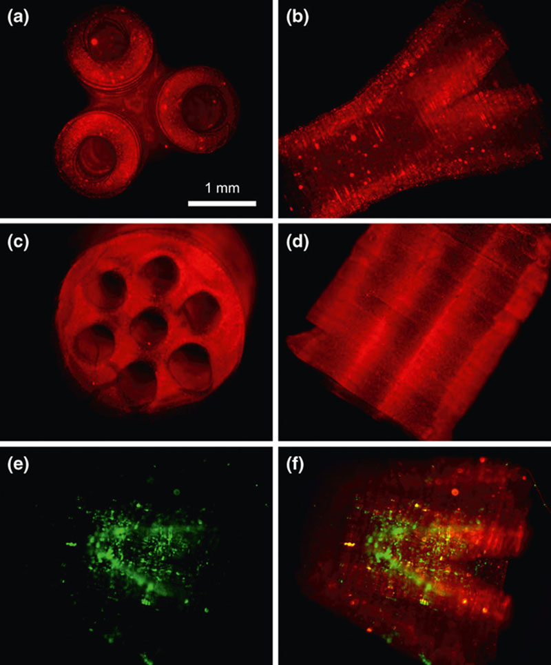
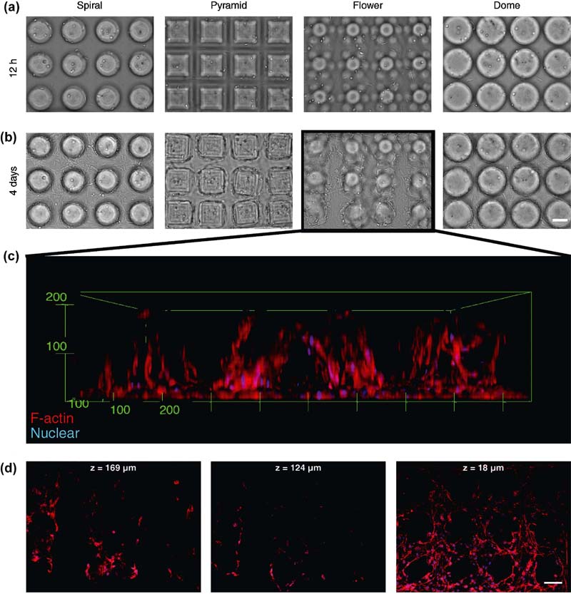
In contrast to the point-by-point processing by laser-based SLA, optical projection stereolithography employs DMD to fabricate 3D hydrogel objects layer-by-layer using UV irradiation. Suri et al. demonstrated the freeform fabrication of nerve regeneration scaffolds with complex microarchitecture using GMHA as shown in Figure 2.7 (Suri et al., 2011). With an improved version of the dynamic optical projection stereolithography (DOPsL) system, Soman et al. succeeded in using GelMA to fabricate complex 3D structures encapsulated with cells (Soman et al., 2013) (Figure 2.8). Live cell-captured scaffold was fabricated with PEGDA using commercialized apparatus (Lin et al., 2012).
image
Figure 2.7 Fluorescence micrographs of the fabricated scaffolds using DMD-based SLA. (a and b) Top and lateral view of the branched scaffold. (c and d) Top and lateral views, respectively, of the multilumen scaffold. (e and f) Schwann cells seeded inside the scaffold. (Scale bar, 1 mm) (Suri et al., 2011).
image
Figure 2.8 Complex 3D cell-encapsulated scaffolds fabricated by the DOPsL system. (a and b) Bright field micrographs of GelMA scaffolds with encapsulated NIH/3T3 cells at different time points. (c) 3D reconstruction of confocal fluorescence micrographs of cell–scaffold interaction. (d) Cross-sections of the confocal images in (c). All scale bars are 100 μm (Soman et al., 2013).
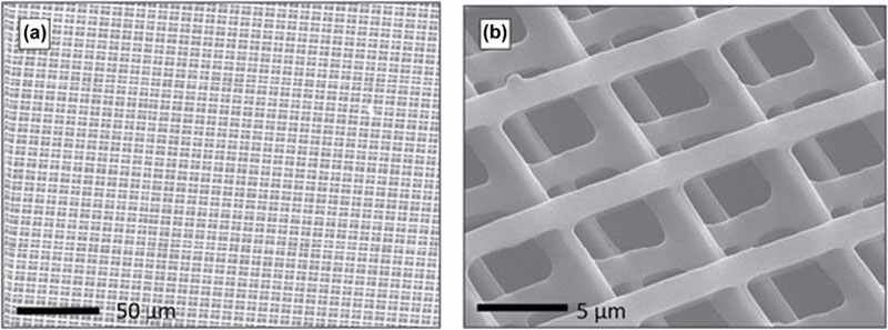
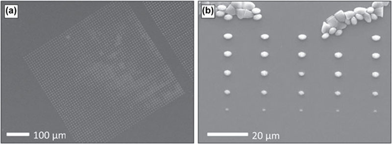
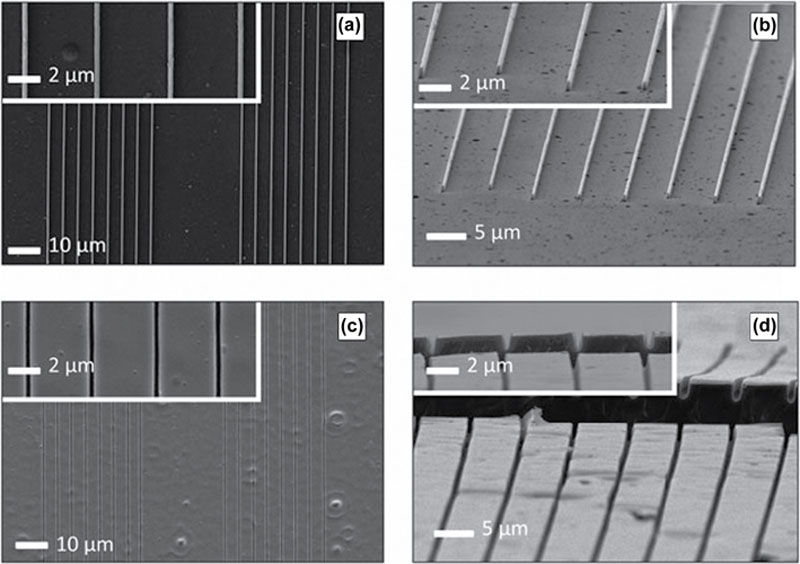
Femtosecond lasers are usually utilized to achieve 2PP for the fabrication of complex 3D structures with very high resolution (<100 nm) and fidelity. Various types of hydrogels are employed in the 2PP lithography. In the work of Zhang and his colleagues, PEGDA was patterned by a Ti:sapphire femtosecond laser into multiple forms of 3D structures, such as woodpile (Figure 2.9) and microdot array with various feature sizes (Figure 2.10) (Zhang and Chen, 2011). These structures can further be used as a mold for the nano-imprinting of other hydrogels (Figure 2.11) (Zhang and Chen, 2011). Methacrylamide-modified gelatin was utilized to create 3D scaffold (Ovsianikov et al., 2011a, 2011b). A kind of natural hydrogel, collagen, and fibrinogen was dissolved in distilled water and printed layer by layer to construct 3D scaffolds (Gebinoga et al., 2013).
image
Figure 2.9 SEM images of woodpile structures fabricated from PEGDA by TPP: (a) large view, (b) close-up view (Zhang and Chen, 2011).
image
Figure 2.10 SEM images of microdot array with various feature sizes fabricated from PEGDA by TPP (Zhang and Chen, 2011).
image
Figure 2.11 SEM images of the dipentaerythritol pentaacrylate (DPPA) mold after imprinting (a and b) and the imprinted PEGDA structures (c and d) (Zhang and Chen, 2011).

2.3.3. Photocurable Polyesters

Photocurable resin (PPF/DEF) was polymerized using a stereolithography system (Lee et al., 2007). PPF is an unsaturated linear polyester that has carbon–carbon double bond cross-linking (Peter et al., 1998). It is degradable by simple hydrolysis of the ester bonds and its product is nontoxic (He et al., 2001). Poly (propylene fumarate) is mixed with diethyl fumarate (DEF) and bisacrylphosphrine oxide (BAPO) as solvent and photoinitiator, respectively. The glass transition temperature and viscosity of PPF and DEF mixture resin is dependent on the weight ratio of PPF and DEF. Glass transition temperature drops dramatically by adding DEF. The viscosity of resin relies on both the weight ratio and the molecular weight of PPF (Lee et al., 2007). Different ranges of laser parameters and resin compositions were employed to analyze the effects on the properties of scaffolds. Considering viscosity and mechanical properties, PPF/DEF mixtures with a 60:40 weight ratio and 1% BAPO might be optimal.

2.4. Cells and Bioapplications

Light-assisted biomanufacturing techniques have been used to fabricate tissue constructs with various types of cells and applications. Two approaches exist: the scaffold-based approach where tissue engineering scaffolds are fabricated first and cells and growth factors are loaded in a separate step; and the bioprinting approach, where cells are encapsulated in biopolymers and patterned into 3D structures. Various cells from cancer cells to stem cells have been used for various applications. Table 2.3 is a summary of the cells used and the applications of each fabrication method.

Table 2.3

Cells and bioapplications

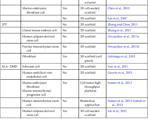
Fabrication techniqueCellsBioprintingApplicationReferences
SLS·No3D scaffoldTan et al., 2005
Human osteoblast-like cellNo3D scaffoldDuan et al., 2010
Fetal femur-derived cellNoBone replacement scaffoldKanczler et al., 2009
Human osteogenic sarcomaNo3D scaffoldLiu et al., 2013
Human gingival fibroblast (HGF)No3D scaffoldWilliams et al., 2005
LGDWEmbryonic chick Spinal cord cellYesCell patterned arrayOdde and Renn, 2000
Human Umbilical-Vein endothelial cell (HUVEC)
Hepatocytes
Multipotent adult progenitor cell (MAPC)
YesTissue architectureNahmias et al., 2005
Endothelial cell
Hepatocyte
YesCell patterning and self-assemblyNahmias and Odde, 2006
Fibroblast
Cardiomyocyte
YesCell patterned arrayNarasimhan et al., 2004
Enbryonic day 7 (E7) chick forebrain neuronYesCell patterned arrayRosenbalm et al., 2006
LIFT
Fibroblast
Keratinocyte
Human mesenchymal stem cell (hMSC)
YesSkin substitute using cell patterningKoch et al., 2009
Porcine mesenchymal stem cell (MSC)YesAutologous graftGruene et al., 2010
Murine fibroblast
Human skin keratinocyte
YesSkin substitute using cell patterningKoch et al., 2012
MAPLEDWPluripotent embryonal carcinoma cellYes3D cell-seeded scaffoldRingeisen et al., 2004
B35 neuronal cellYes3D cell-seeded scaffoldPatz et al., 2006
Human osteosarcomaYes3D cell-seeded scaffoldDoraiswamy et al., 2007
BioLPHuman osteosarcoma cellYes3D cell-seeded scaffoldBarron et al., 2004; Barron et al., 2004; Barron et al., 2005
Olfactory ensheathing cellYes3D cell-seeded scaffoldOthon et al., 2008
SLA - laserMurine bone-marrow stromal cellNo3D scaffoldMapili et al., 2005
CardiomyocyteNoCell-based biohybrid actuatorChan et al., 2012
Murine embryonic fibroblast cellYes3D cell-seeded scaffoldChan et al., 2010
·No3D scaffoldLee et al., 2007
2PP·No3D scaffoldZhang and Chen, 2011
Clonal mouse embryo cellNo3D scaffoldZhang et al., 2013
Human adipose-derived stem cellNo3D scaffoldOvsianikov et al., 2011a
Porcine mesenchymal stem cellNo3D scaffoldOvsianikov et al., 2011b
FibroblastYes3D scaffold (cell glued)Gebinoga et al., 2013
SLA - DMDSchwann cellNo3D scaffoldSuri et al., 2011
Human umbilical vein endothelial cellNo3D scaffoldGauvin et al., 2012
Murine embryonic fibroblast
Murine mesenchymal progenitor cell
YesCell-laden high-throughput platformSoman et al., 2013
Human mesenchymal stem cellNoBiomedical applicationSoman et al., 2012; Soman et al., 2012
Human adipose-derived stem cellYes3D cell-seeded scaffoldLin et al., 2012


2.4.1. Scaffold-Based Approach to Tissue Constructs

Human osteoblast-like (SaOS-2) cells were seeded on nanocomposite scaffolds produced using SLS with Ca-P/PHBV and CHA/PLLA nanocomposite spheres in order to evaluate biomimetic environment (Duan et al., 2010). The Ca-P/PHBV nanocomposite scaffolds were sintered at 15 W laser power, 1257 mm/s scan speed, and part bed temperature of 35°C. For CHA/PLLA scaffolds, the nanocomposites were sintered with a laser power of 15 W using the same scanning speed at a part bed temperature of 45°C. The pore size was designed to be 0.8 mm3. The porosities of fabricated structures were 62.6 ± 1.3% (Ca-P/ PHBV) and 66.8 ± 2.5% (CHA/PLLA), respectively, although the porosity of the designed model was calculated to be 52.7% using a computer program. Alkaline phosphatase (ALP) activity was measured, since ALP is an enzyme used as a biomarker of the osteogenic phenotype. It can catalyze the hydrolysis of phosphate esters at alkaline pH and influences on the bone matrix mineralization. ALP activity kept increasing until 7 days after seeding, but decreased between 7 days and 14 days. This is because ALP is an early marker for osteogenic differentiation and it decreases with initiation of the mineralization process (Kim et al., 2006). There was no significant difference in cell proliferation and ALP activity between two nanocomposite scaffolds.
Human fetal femur-derived cells were cultured in poly (d,l)-lactic acid (PLA) scaffolds in vitro and in vivo to evaluate the scaffold fabricated with SLS (Kanczler et al., 2009). PLA powder mixed with carbon black was sintered with a continuous wave fiber diode laser having an energy density of about 100 ± 20 W/cm2. The scan speed was 3 mm/s. Cell proliferation and histological characteristic were evaluated after 7 days of cell culturing. A PLA scaffold containing human fetal femur-derived cells after 24 h cell culture was subcutaneously implanted in female MF-1 nu/nu immunodeficient mice. After 28 days, the tissue scaffold in vivo was evaluated by staining for Acian blue/ Sirius red and for the expression of type I collagen. This study provided a platform for the differentiation of human fetal femur-derived cells to generate new cartilaginous and osteogenic matrices.
A biomedical titanium bone scaffold was fabricated using SLS (Liu et al., 2013). The laser was tuned at laser power of 15 W and a scanning speed of 100 mm/s. The scaffold showed a 142 MPa compressive strength after post-heat treatment at 800°C and proved suitable biocompatibility after cultivation of human osteogenic sarcoma cells (MG63).
A laser-based stereolithography was employed to create predesigned internal architecture and porosities of scaffold with PEGDMA (Mapili et al., 2008). The 3D scaffold was fabricated using Nd:YAG laser having laser energy of ∼10 mJ/pulse. The scanning speed on xy direction was about 50 μm/s. Measured pore size and wall thickness of microfabricated scaffolds were ∼425 and ∼200 μm, respectively. PEG acrylates were modified with the peptide arginine–glycine–aspartic acid (RGD) or the ECM component heparin sulfate, and was later contained within the scaffold to enhance cell adhesion and allow spatial sequestration of heparin-binding growth factor. After the modification, murine bone-marrow stromal cells were seeded and cultured on the scaffolds for 24 h. Cell attachment was evaluated using confocal fluorescence images.
The biohybrid actuator was fabricated using laser-based SLA with PEGDA (Chan et al., 2012). The cantilever-shaped actuator was created by using commercial apparatus. The fabricated cantilever beam measured 2 mm wide, 4 mm long, and 0.45 mm thick. Cardiomyocytes were seeded on the cantilever and bending of the actuator was measured to analyze the traction forces created by cells.
2PP was used to fabricate woodpile scaffold with PEGDA (Zhang and Chen, 2011). The power of the Ti:sapphire femtosecond laser (wavelength 800 nm) was adjusted by rotating a beam attenuator. The woodpile consisted of 1 μm wide lines with spacing of 8 μm. The distance between layers was 3 μm. Woodpile scaffolds could be used for cell transmigration study, where spacing between lines was chosen similar to the typical size of cancer cells. The distance among each line could be changed according to the size of cells. 10T1/2 cells were seeded on the web structures with various shapes for tuning Poisson’s ratio, which was hypothesized to change cell response (Zhang et al., 2013).
GelMod was utilized to fabricate a 3D scaffold used for adipose-derived stem cell (ASC) adhesion, proliferation, and differentiation into adipogenic lineage (Ovsianikov et al., 2011a). A cavity-dumped oscillator was employed for femtosecond laser. A layer of scaffolds was produced at a scanning speed of 10 mm/s with a constant average laser power of 3.5 mW. Each layer had a distance of 15 μm. The pore size was a square cross-section of 250 μm by 250 μm. Cell adhesion and proliferation were evaluated using cell staining and fluorescence image analysis. The differentiation into adipogenic lineage was assessed by using Oil Red O staining. Ovsianikov et al. conducted a similar study on fabricated 3D scaffold using 2PP with GelMod (Ovsianikov et al., 2011b). Instead of analysis of cell differentiation, degradation of hydrogels was investigated by measuring mass loss of fabricated scaffolds in the presence of collagenase (Type I, collagenase digestion unit (CDU)). Degradation of scaffolds depended on incubation time. Incubation time of 3–4 h was needed to degrade half of the scaffolds.
Stereolithography using DMD was used to fabricate scaffold for tissue engineering with GMHA. The DMD is composed of an array of micromirrors (1024 by 768) (Suri et al., 2011). For polymerization, the power of UV light was determined to be ∼ 8 mW/cm2 and each layer was exposed under UV light for 30 s. A platform having polymerized layer moved downward 0.5 mm for each layer. The pore sizes were 100–200 μm in one side and diameter with hexagonal and circular geometries, respectively. After the protein grafting process, Schwann cells were seeded and cultured for 24 h. Scaffold degradation was performed in 500 U/ml of hyaluronidase. The longer the UV exposure time the slower the degradation of the scaffold. This is because longer UV exposure could lead to a higher cross-linking density. Cell adhesion was analyzed and the scaffolds represented cell adhesion and retention of cell viability for at least 36 h.
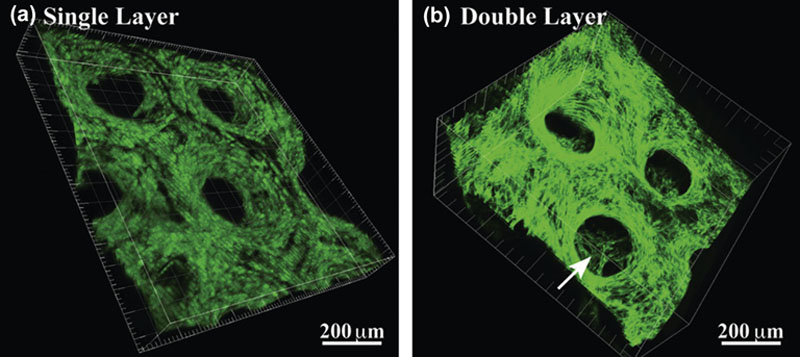
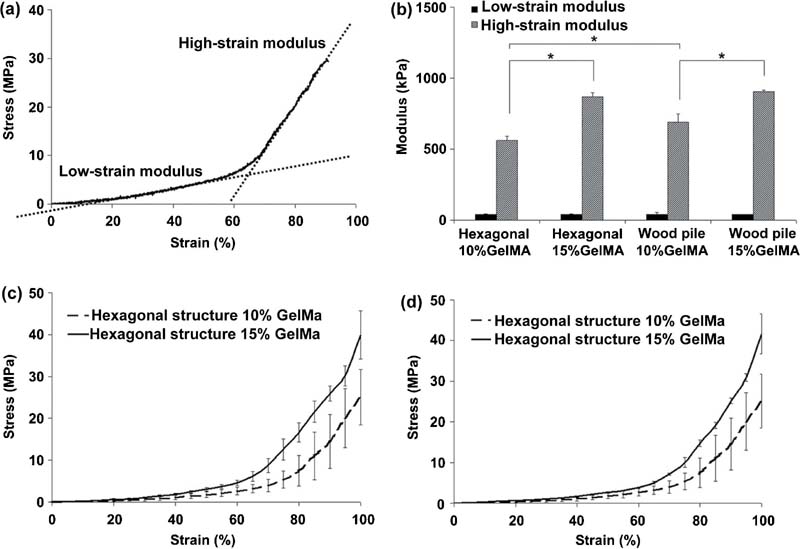
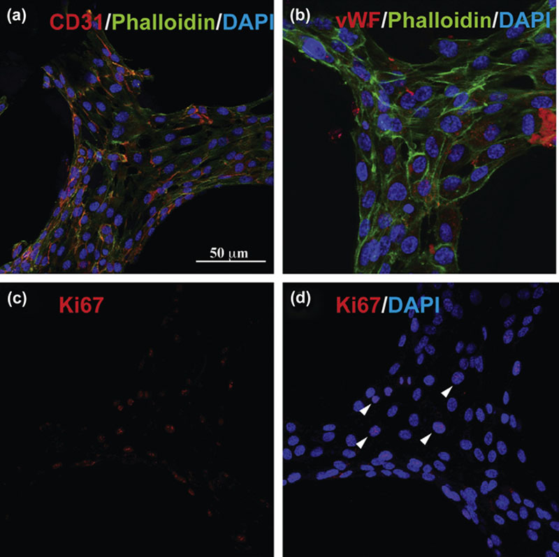
Human umbilical vein endothelial cells (HUVECs) were seeded on 3D scaffolds fabricated with GelMA via DMD-SL (Figure 2.12) (Gauvin et al., 2012). The created scaffold had a dimension of ∼2 mm with a micrometer-scale resolution. Unconfined compression test was conducted for scaffolds with different designs, the results of which are biphasic stress–strain curves consisting of low-strain (20–40%) and high-strain (70–90%) compressive moduli (Figure 2.13). At the higher strain stage, the stress–strain relationship showed a linear behavior similar to that of elastic materials. Cell viability, proliferation, and functionality were evaluated by using a confocal microscope after fluorescence staining, which demonstrated that the scaffolds can support cell adhesion and proliferation without damaging the biological function and phenotype of the cells (Figure 2.14).
image
Figure 2.12 3D confocal images of the HUVEC-GFP seeded single- (A) and multi- (B) layer scaffolds with precisely defined hexagonal geometries (Gauvin et al., 2012).
image
Figure 2.13 Mechanical properties of the 3D scaffolds with hexagonal or woodpile structures using different GelMA concentrations (Gauvin et al., 2012).
image
Figure 2.14 Immunofluorescence images showing the biological functionality of the HUVEC seeded scaffolds (Gauvin et al., 2012).
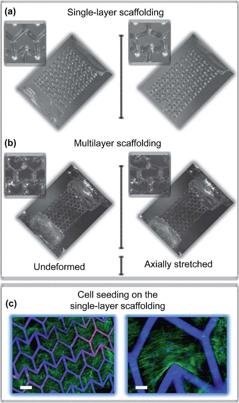
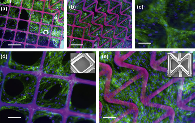
Elastic modulus and Poisson’s ratio are two fundamental mechanical properties that reflect the tissue-engineered scaffolds’ ability to handle various loading conditions (Soman et al., 2012). While elastic modulus can be easily tuned by the compositions and fabrication conditions, it is substantially more challenging to tune the Poisson’s ratio of the scaffolds (Soman et al., 2012). In the work of Soman and his colleagues, scaffolds with various Poisson’s ratio (negative, positive, and zero) were constructed using PEGDA via DMD-SL, as shown in Figures 2.15 and 2.16 (Soman et al., 2012). Human mesenchymal stem cells (hMSCs) were seeded and cultured on the scaffolds to demonstrate the feasibility of these scaffolds for tissue engineering and other biological applications. As long as the scaffolds are deformed in elastic region, Poisson’s ratio is solely dependent on the geometry of scaffolds. Thus, the tunable Poisson’s ratio property can be imparted to any photocurable materials, which shows great promise for a variety of bioengineering applications (Soman et al., 2012).
image
Figure 2.15 Optical images showing the deformation of a (A) single- and (B) multilayer ZPR PEG scaffold in response to an axial strain. (C) Fluorescence images of hMSCs seeded on a single-layer ZPR PEGDA scaffold. Green: F-actin. Blue: cell nuclei and scaffold. Scale bars represent (left) 200 μm and (right) 50 μm (Soman et al., 2012).
image
Figure 2.16 Fluorescence microscopy images of hMSCs seeded on (A, D) positive Poisson ratio (PPR) region and (B, C, E) negative Poisson ratio (NPR) region. (C) Cells growing in scaffold voids and along scaffold struts in NPR region. (D) Cells growing along scaffold struts (inset: SEM of scaffold struts) in PPR region. (E) Cells seeded on NPR region (inset: SEM of scaffold struts). Scale bars represent (A, B) 250 μm and (C, D, E) 125 μm. Green: actin filaments; blue: nuclei; pink: scaffold struts (Soman et al., 2012).

2.4.2. Bioprinting Approach to Tissue Constructs

Embryonic chick spinal cord cells were patterned on untreated glass surface using LGDW in order to fabricate small arrays of cells for the cell–cell interaction study (Odde and Renn, 2000). A tunable diode laser beam was employed at 450 mW laser power. For long-range transport of cells, the hollow optical fibers were coupled with a laser beam. A laser beam having 800 nm wavelength created gradient force, which propelled cells into the center of the beam at a mean velocity of 11.4 μm/s. The average deposition rate was 2.5 cells/min. In the hollow-fiber experiment, the cells traveled distances of up to 7 mm.
HUVECs were guided on a Matrigel®-coated slide to fabricate two- and three-dimensional cell patterns using LGDW (Nahmias et al., 2005). LGDW employed a weakly focused diode laser beam having 200 mW laser power and 830 nm wavelength. The specific cell patterning protocol was developed and described by Nahmias et al. (Nahmias and Odde, 2006). HUVECs were guided in a mixture of culture medium and Percoll solution (40%). Endothelial viability after patterning was 89% ± 7%. The vascular structure of HUVEC (200 μm) was patterned using LGDW and self-assembly of cells. Hepatocytes were then seeded on the fabricated structure to create a sinusoid-like structure, which is one of the structural elements of the liver. The optimal seeding density was 50,000 cells per cm2 for both endothelial and hepatocytes to create robust formation.
Multiple laser beams were used to pattern fibroblasts on collagen-coated substrate with and without myocyte culture (Narasimhan et al., 2004). Ti:sapphire laser beams had a wavelength of 780 nm. Beam 1 and Beam 2 were perpendicularly aligned on an xy plane that was vertical to the substrate (z-direction). Beam 2 vertical (x) to z-direction had a higher laser intensity than beam 1 (y) parallel to z-direction. This resulted in a slightly higher velocity for x-direction compared to that for y-direction. The velocity was in the range of 45–150 μm/s.
Embryonic day 7 (E7) chick forebrain neurons were subjected to Ti:sapphire laser having 800 nm wavelength (Rosenbalm et al., 2006). Two experiment parameter settings were compared to control (cell culture without laser exposure): laser intensity of 300 mW at 60 s and one of 100 mW at 10 s. The extension length of neurite was measured to analyze the influence of laser on neurons. There was no significant difference in results. Rosenbalm et al. concluded that LGDW is a safe method for cell patterning.
The LIFT technique was applied to print human skin cells, NIH3T3 fibroblasts, and HaCaT keratinocytes, and human mesenchymal stem cells (hMSC) using Nd:YAG laser (Koch et al., 2009). The donor slide was sputter-coated with a 55–60 nm thick gold and was covered with about 50 μm thick cell-containing layer. Laser having 1064 nm wavelength and 3–6 J/cm2 fluence transferred a cell-suspended mixture of alginate and blood plasma on the Matrigel®-coated collector slide. Biological material droplets were printed in droplet diameter of 80–140 μm with a speed of 1200 droplets per minute. The cell viabilities were 98% ± 1% for skin cells and 90% ± 10% for human stem cells after laser printing. Apoptosis and genotoxicity were tested to evaluate the damage to cells and DNA, respectively, and the results proved that LIFT has no significant influence on cells and DNA. The result of fluorescence activated cell sorting (FACS) analysis described that the phenotype of hMSC was not affected by LIFT.
Porcine mesenchymal stem cells (MSC) were printed on the hydrogel-covered collector slide using LIFT (Gruene et al., 2010). Gold was sputter-coated on the donor slide in 55–60 μm thickness, and then the cell suspension was covered in ∼65 μm thickness on gold layer. Parameters of Nd:YAG laser were fixed with 1046 wavelength and 2.15 J/cm2 laser fluence. There was no significant difference in viability between laser-printed cells and control (cells without laser exposure). No damage to DNA was observed. ALP activity was measured to evaluate and compare the osteogenic differentiation between laser-printed cells and control. Immunofluorescence staining and Alcian blue staining were conducted to detect the presence of type II collagen and aggrecan, and to quantify sulfated glycosaminoglycan (sGAG). The results supported that MSC differentiated to bone. Koch et al. also three-dimensionally patterned NIH3T3 fibroblasts and HaCaT keratinocytes (Koch et al., 2012). Twenty layers of each cell line were stacked to mimic 3D skin structure.
MAPLEDW was utilized on biomaterials containing pluripotent embryonal carcinoma cells (P19) onto Matrigel®-coated quartz substrate (Ringeisen et al., 2004). Matrigel® was spin-coated on quartz 10–30 μm thickness, and the substrate had a Matrigel® layer on its cell receiving face. An ArF excimer laser was set with 193 nm wavelength and 400 mJ/cm2 laser fluence. Cell viability was over 95% for 24 h post-transfer. The comet assay was employed to evaluate DNA damage; the results showed no noticeable damage. Cell differentiation was induced via adding retinoic acid or dimethyl sulfoxide (DMSO; 1%). The immunofluorescence staining test proved that P19 cells were differentiated into neuronal and muscle cells.
B35 neuronal cells were transferred onto a Matrigel®-coated quartz substrate using an ArF laser (193 nm wavelength) (Patz et al., 2006). The ribbon consisted of transparent quartz and cell-seeded Matrigel® matrix. The matrix was printed onto the substrate via a laser beam having a laser fluence range of 0.02 to 0.08 J/cm2. Terminal deoxynucleotidyl transferase biotin-dUTP nick end labeling (TUNEL) immunostaining was used to detect cell apoptosis. The α-tubulin immunofluorescence staining was employed to examine axon morphology. TUNEL staining image showed that 3% of B35 neuronal cells were in apoptosis after 96 h. Analysis of axonal projection showed no significant impairment after the MAPLEDW process. The penetration of cells within the Matrigel® substrate was observed using a confocal microscope and the maximum depth was 75 μm.
Human osteosarcomas (MG-63) were codeposited with bioceramic, hydroxyapatite, and zirconia, using MAPLEDW (Doraiswamy et al., 2007). Hydroxyapatite or zirconia powder solvated in glycerol:water matrices were spin-coated onto a quartz ribbon. ECM was covered onto the bioceramic-coated ribbon then MG-63 cells were seeded on the ribbon. ECM was spin-coated on quartz without any bioceramic in order to compare cell viabilities of ribbon with and without bioceramic. An ArF pulsed excimer laser was set with 193 nm wavelength at 0.22 and 0.18 J/cm2 laser fluence for hydroxyapatite and zirconia, respectively. Scanning electron microscopy (SEM) and fluorescence images were investigated to analyze morphologies of transferred cells and bioceramics. There was no discernible difference in cell viability between ECM cells deposition and ECM cells bioceramic structure.
BioLP was employed to pattern a multilayer structure with MG-63 cells (Barron et al., 2004). The optical setup was designed with Nd:YAG laser having 266 nm wavelength. The biomaterials consisted of human osteosarcoma cells, culture medium, and 5% of glycerol (v/v). It was transferred onto the Matrigel® substrate with laser fluence of 160 mJ/cm2 at a deposition rate of 100 spots/s. The patterned cell layer was covered by Matrigel® to print other layers on it. Live/dead fluorescence staining and a confocal microscope were used to evaluate cell viability and morphology of multilayered cell printing. Barron et al. also published a paper concerning BioLP with a similar setup (Barron et al., 2004). The fluorescence image was investigated to evaluate MG-63 cell viability; it showed 95% cell viability. Human osteosarcoma cells were patterned using a similar printing mechanism by Barron et al. (Barron et al., 2005). Immunocytochemical staining was utilized to investigate heat shock protein (HSP) expression. The expression of mouse IgG anti-HSP60 and anti-HSP 70 represented no significant cell impairment.
Olfactory ensheathing cells (OECs) were printed onto the Matrigel® substrate using BioLP in order to fabricate a 3D scaffold (Othon et al., 2008). Titanium or titanium oxide was coated on the transparent quartz ribbon as a laser absorption layer, and then a cell/culture medium solution (0.35% methylcellulose) was applied on the metal or metal oxide layer. Nd:YAG laser was used with a setup of 266 nm wavelength and 4 mJ laser energy. A glass substrate was coated with Matrigel® and translated at the maximum speed of 75 mm/s. Live/dead assay and immunocytochemistry were investigated to evaluate cell viability and cell–cell interaction.
Murine embryonic fibroblast cells (NIH/3T3) were encapsulated in PEGDA hydrogel 3D structures using stereolithography apparatus (Chan et al., 2010). The cells were suspended in the prepolymer solution composed of 20% (w/v) PEGDA, 0.5% (w/v) photoinitiator, and 10% fetal bovine serum (FBS) in Dulbecco’s modified Eagle’s medium (DMEM). Cell viability and cell spreading were measured and evaluated after cell staining. It was observed that adhesive RGDS peptide sequences have a positive effect on cell viability, proliferation, and spreading.
2PP was used to fabricate a 3D collagen structure containing Fibroblast cells (L929) (Gebinoga et al., 2013). A femtosecond pulsed laser was employed with 780 nm wavelength at a repetition rate of 82 MHz. The laser was focused on a focal area of 280 mm in diameter with 4.5 × 10⁻¹⁰ J pulse energy. Collagenase digestion experiments were conducted to investigate in vitro degradation of the collagen structure. Immunofluorescence staining was performed using staining patterns of antibodies. The polymerized line was about 1 μm at a printing speed of 5 μm/s. The collagen structures were not degraded by collagenase I and liberase, but by Terazyme in 24 h. These represented that the laser-patterned collagen structure had a strong cross-link and consisted of native collagen.
Stereolithography was used to print cell-laden hydrogel 3D structures using DMD (Soman et al., 2013). Murine mesenchymal progenitor cells (C3H/10T1/2) and NIH/3T3 cells were encapsulated in GelMA using UV irradiation. UV light had 365 nm wavelength and 11 mW/cm2 UV intensity. A cell containing GelMA was exposed to UV light for 35 s to pattern each layer. Cell morphology and viability were investigated using immunohistochemical staining. F-actin, α-SM actin, and Hoechst 33258 DNA dye was applied to stain NIH/3T3 cells, C3H/10T1/2 cells, and nuclei, respectively. The resolution in each layer was ∼17 μm × 17 μm. There is no significant viability difference between the 3D structure and the control slab. The proliferation was different among locations in the 3D structure due to nutrient concentration gradients.
Human adipose-derived stem cells (hADSCs) were patterned in PEGDA using a projection stereolithography apparatus (Lin et al., 2012). Lin et al. developed an SLA system using a visible light in order to reduce UV light’s potential to damage the cellular DNA. The stem cells were suspended in PEGDA solution with photoinitiator (lithium phenyl-2,4,6-trimethylbensoylphosphinate (LAP)) and were captured by a visible light. Minimum pixel size printed was about 68 μm square. The pore size of the fabricated structure was 300 μm × 300 μm. MTS assay was performed to estimate cell viability, and its result indicated over 90% viability after 7 days.

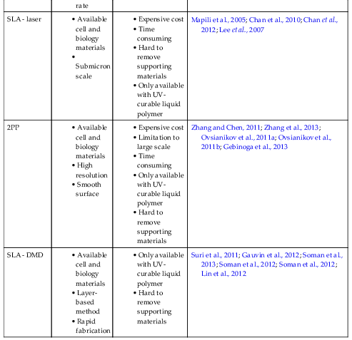
2.5. Discussion: Pros and Cons of Each Technique

Additive manufacturing techniques using laser for bioapplications can be classified into four groups based on the patterning mechanism: laser sintering, laser-writing, laser-transferring, and stereolithography methods. The pros and cons of these techniques are listed in Table 2.4. SLS only prints powder-type materials. It can sinter a variety of materials including biometals, which cannot be achieved by other methods. In addition, the scaffolds fabricated by SLS represent better mechanical strength compared to the ones fabricated by other methods. However, high-power laser is employed to melt and pattern powder-type materials; therefore, SLS can only pattern biomaterials, not cells. The laser-guided direct writing method prints each cell using a gradient force induced by a near-infrared laser. It can achieve a relatively high resolution (∼ 1 μm). In addition, a cell can be guided onto a certain location using multiple lasers. However, scaling up this LGDW technique to fabricate fully 3D structures still remains a challenge. This is because cells are written in a cell by cell fashion at a deposition rate of 2.5 cells/min and cells are seeded on a biological gel layer. Techniques using the laser-transferring mechanism utilize the evaporation of laser absorption layer (typically gold) or cell containing biopolymers. LIFT, MAPLEDW, and BioLP have a higher fabrication rate comparing to LGDW, since they transfer biomaterial drops containing multiple cells. Cell-encapsulated 3D structures can be created using those transferring methods. MAPLEDW employs the simplest ribbon among these techniques. The ribbon is only coated by hydrogels, which is volatilized by UV laser. However, the laser absorption rate of MAPLEDW is lower than LIFT and BioLP. Evaporation of laser absorption layer is used to transfer biological materials onto the collector slide by LIFT. In the case of BioLP, the laser absorption layer is inserted between the transparent quartz and cell suspended biomaterial layer. The volatilization of cell-containing matrix transfers the biomaterial and cells onto the substrate. Stereolithography methods fabricate both 3D scaffolds and 3D cell-laden structures. For 3D scaffolds, the resolution of the stereolithography method, especially 2PP, is on the submicron or nanometer scale. However, in the case of bioprinting, the resolution of stereolithography is limited by the size of cells. Compared to other methods, stereolithography can help create more complex geometries. Stereolithography using DMD has the fastest fabrication rate, since it creates hydrogel patterns in a layer-by-layer fashion (1 layer per 20–35 s). As an expense of high resolution, a more complex experimental setup is required.
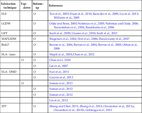
Table 2.4

Pros and cons of each technique

Fabrication techniqueAdvantagesDisadvantagesReferences
SLS
High-strength object
Self-support process
Variety of materials
Limitation to powder form
Rough surface
Hard to remove supporting materials
Impossible to print cells or biological materials
Tan et al., 2005; Duan et al., 2010; Kanczler et al., 2009; Liu et al., 2013
LGDW
Available cell and biology materials
Single cell resolution
Precise cell printing
Hard to build full 3D structure
Time consuming
Low cell viability (up to 95%)
Odde and Renn, 2000; Nahmias et al., 2005; Nahmias and Odde, 2006; Narasimhan et al., 2004; Rosenbalm et al., 2006
LIFT
3D structure
Available cell and biology materials
High cell viability (∼95%)
Weak structural support
Koch et al., 2009; Gruene et al., 2010; Koch et al., 2012
MAPLEDW
Available cell and biology materials
High cell viability (near 100%)
Simple donor slide
Weak structural support
Low reproducibility
Ringeisen et al., 2004; Patz et al., 2006; Doraiswamy et al., 2007
BioLP
Available cell and biology materials
High efficiency (99% of incident)
High cell viability (∼ 95%)
Rapid printing rate
Weak structural support
Metal or metal oxide layer inserted
Barron et al., 2004; Barron et al., 2004; Barron et al., 2005; Othon et al., 2008
SLA - laser
Available cell and biology materials
Submicron scale
Expensive cost
Time consuming
Hard to remove supporting materials
Only available with UV-curable liquid polymer
Mapili et al., 2005; Chan et al., 2010; Chan et al., 2012; Lee et al., 2007
2PP
Available cell and biology materials
High resolution
Smooth surface
Expensive cost
Limitation to large scale
Time consuming
Only available with UV-curable liquid polymer
Hard to remove supporting materials
Zhang and Chen, 2011; Zhang et al., 2013; Ovsianikov et al., 2011a; Ovsianikov et al., 2011b; Gebinoga et al., 2013
SLA - DMD
Available cell and biology materials
Layer-based method
Rapid fabrication
Only available with UV-curable liquid polymer
Hard to remove supporting materials
Suri et al., 2011; Gauvin et al., 2012; Soman et al., 2013; Soman et al., 2012; Soman et al., 2012; Lin et al., 2012


Laser-based printing is a noncontact printing method. It shares one main advantage with all noncontact printing methods—reduced contamination. During the process, the printing device and the target substrate are always separate thereby reducing the possibility of contamination (Stratakis et al., 2009).

2.6. Summary

Over the past few decades, a variety of 3D printing and nanomanufacturing techniques have emerged with the development of laser technology, CAD techniques, and digital microelectronic devices. Rapid and automatic manufacturing of 3D structures ranging from nanoscale to macroscale has been achieved. The efficiency, flexibility, resolution, and versatility of these 3D printing and nanomanufacturing techniques have generated much excitement in the field of biomedical engineering. AM methods using laser utilize diverse laser sources, materials, and experimental setups. Ultraviolet and near-infrared laser are used to fabricate structures. Donner slide and ribbon are coated by various materials from hydrogel to bioceramics. All structures are designed using CAD layer by layer and printed via laser. These additive manufacturing techniques are applied to a wide range of fields, such as investigation of tumor cell development and progression, regeneration of tissue replacement, and bioactuators, to name a few. Many have reported biocompatibility, resolution, and efficiency of fabricated scaffolds, as well as good cell viability, proliferation, DNA differentiation, and cell–cell interaction. There is no significant change of phenotype, cell damage, and DNA impairment. Compared with other techniques, such as ink-jet and micropen printing, laser-based AMs provide a versatile approach to tissue or organ printing (Mironov et al., 2009). With more and more biomaterials and cell-lines becoming available, tremendous work has been done to apply and make the best use of these 3D printing techniques in both basic biological research and clinical medicine. For instance, engineered functional tissues have shown great promise for in vitro drug test as well as in vivo transplantation. Medical devices integrated with biomimetic 3D microarchitectures are also revolutionizing traditional healthcare research and industry. While the ultimate goal of 3D printing of functional human organs seems elusive for now, given the limitations of the material, cell-line, and the 3D manufacturing process, the development of 3D bioprinting techniques will continue to expand with potential applications in tissue engineering and regenerative medicine.