Chapter 5

Engineering 2D and 3D Cellular Microenvironments Using Laser Direct Write

Andrew D. Dias
David M. Kingsley
David T. Corr    Department of Biomedical Engineering, Rensselaer Polytechnic Institute, Troy, NY, USA

Abstract

Advances in biology and medicine have created a number of applications that demand greater control over the features that comprise the cellular microenvironment. In areas such as tissue engineering, in vitro diagnostics, and directed stem cell differentiation, it is important to manipulate specific microenvironmental features using engineering approaches to influence cell–material (cell–substrate) and cell–cell interactions. One way by which this can be achieved is using a high-resolution, spatially precise cell printing technique that is compatible with engineered materials. A patterning approach of particular interest is laser direct-write (LDW), a forward transfer technique that has been further developed to print biological materials and viable cells with high spatial precision in customizable patterns in 2D, and more recently in 3D microenvironments. The flexibility of LDW (2D and/or 3D) combined with substrates of controllable features (e.g. hydrogels, electrospun fibers) grants unprecedented control in microenvironment fabrication, allowing novel applications and fundamental research questions to be explored.

Keywords

3D printing
bioprinting
hydrogels
laser direct-write
microbeads
microenvironment

5.1. Introduction

5.1.1. Spatial Influences of the Cellular Microenvironment

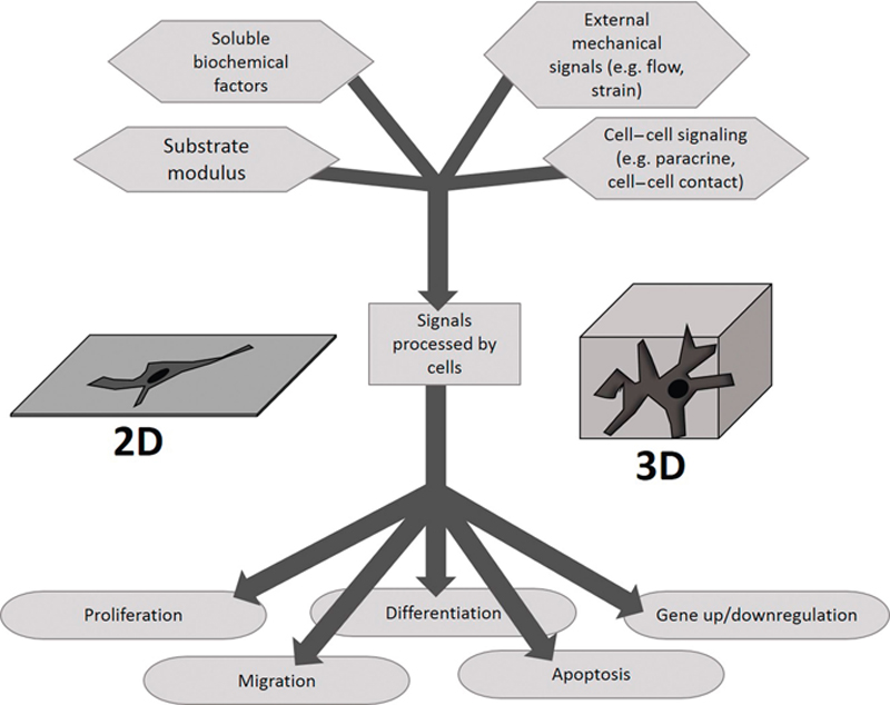
For tissue engineering and regenerative medicine, engineered cell microenvironments, or niches, provide a platform for directing cell fate and function. In other words, cellular behavior is influenced by the signaling of various stimuli provided by the local environment. Signals can be soluble, mechanical, and/or cellular, and the origin and transduction of each type of signal is potentially very broad and complex (Figure 5.1). The effect and/or potency of these signaling mechanisms can be influenced by distance, time, frequency, and concentration, among other variables. This concept has been reviewed extensively (Lund et al., 2009; Freytes et al., 2009; Godier et al., 2008), and can be applied to a variety of tissue engineering applications, such as creating cellular scaffolds/functional constructs, directing stem cell differentiation, and inducing desired cellular alignment, migration, proliferation, or protein production. There are numerous engineering approaches to produce microenvironments, such as introducing growth factors into cellular media, engineering substrates of desired material properties, creating 3D hydrogels, and delivering mechanical stimuli, such as flow, tension, or compression. All of these approaches take advantage of signaling mechanisms inherent in cells, such as cellular receptors for soluble signals and transduction through the cytoskeleton for mechanical signals. However, in vivo cellular communication is very sophisticated, and cells respond to more biochemical and mechanical signals than can typically be controlled in vitro. The mechanisms of cell-cell signaling are spatially dependent, where cells a short distance from each other can communicate by paracrine signaling, and cells immediately adjacent can communicate by direct cell-cell contact or juxtacrine signaling. One of the challenges facing emerging applications is how to harness this complex signaling to better direct cell fate and function in vitro. The cellular microenvironment is further complicated by cellular population dynamics, such as the composition and distance of a neighboring population of cells, size of populations/colonies, and of course, the types of cells within the environment. The fact that neighboring cells influence cell behaviors, and that intercellular spacing is a determining factor for the mode of communication, suggest that spatial sensitivity and control is highly desirable in many emerging tissue engineering and regenerative medicine applications.
image
Figure 5.1 Cellular signaling schematic. Cells can receive a wide variety of input signals from the microenvironment, which they process to produce any number of outputs. The combination of signals can potentially be very complex.
In addition to cell placement, control over adsorbed/encapsulated proteins may have a profound effect on cellular behavior. Cell–cell and cell–extracellular matrix (ECM) interactions are spatially sensitive, and examples of how they influence cell signaling are shown in Figure 5.1. Whether the cellular microenvironments are planar or are 3D is also very important, since depending on the application, switching from 2D to 3D (or vice versa) can greatly impact cell signaling, function, and fate. In order to harness the cells’ natural ability to process complex environmental signals, 2D/3D approaches for engineering cellular microenvironments must not only provide a degree of spatial control in fabrication, but must also control the density/concentration of cells, proteins, or other factors at these locations. Various printing/patterning techniques may be appropriate depending on the desired application, and we will briefly examine a few, weighing their potential advantages and disadvantages. We will pay particular attention to laser direct-write (LDW).

5.1.2. Overview of Printing Techniques for Engineering Cellular Microenvironments

A number of patterning, deposition, and printing techniques have been employed to achieve spatial control in engineered microenvironments. Various biologics, including proteins, nucleic acids, and even viable cells have been successfully deposited with spatial precision. Some of the early work for cell patterning involved controlled spatial adsorption of an adhesive protein, with subsequent seeding of cells that preferentially grow on the patterned protein. While this sort of patterning was first demonstrated using lithography-based techniques such as microcontact printing (Chen et al., 1998; Tien et al., 2002), other deposition methods like ink-jet printing (reviewed in (Calvert, 2001)) and LDW (Ringeisen et al., 2002a; Wu et al., 2003; Colina et al., 2005) have also shown successful protein or nucleic acid deposition. Moreover, ink-jet printing (Xu et al., 2005; Roth et al., 2004; Saunders et al., 2008) and LDW (Odde et al., 2000; Pirlo et al., 2006; Barron et al., 2004a; Schiele et al., 2010; Schiele et al., 2011) have been used to deposit viable mammalian cells directly to a homogeneous substrate, without requiring the prior patterning of a protein. There are other patterning techniques available, such as dip-pen nanolithography (Piner et al., 1999) or AFM-based patterning (Xie et al., 2006), that focus on patterning at submicron scales. Cells certainly sense nanoscale features in their environments, but in order to study and produce cellular microenvironments where cell- and population-level interactions are controlled, patterning at the micro- and mesoscale may be most relevant for directing cellular signaling. However, patterning at this scale can be quite challenging; it is too large to be accomplished directly by chemistry, and too small to use many traditional fabrication methods.
Some methods that have proven suitable for patterning at this scale include microcontact printing, ink-jet printing, and LDW. Each of these has its own specific advantages and disadvantages, and they are quite complementary. Microcontact printing employs a stamp with relief features attained via photolithography. The resolution of the pattern is limited only by the wavelength of light, making submicron resolution attainable with this technique. By contrast, LDW is a noncontact technique that propels material to a substrate by laser energy absorption and partial volatilization of a sacrificial layer. The spatial location of the transferred material is determined by the programmed position of a computer-aided design/computer-aided manufacturing (CAD/CAM) stage. The resolution of this technique can be under 10 μm (Zhang et al., 2003), because of the dynamics of the material transfer event and controlled stage movement. Ink-jet printing, by comparison, has a printing resolution on the order of 50 μm (Calvert, 2001), which is appreciably lower but still very good. Material deposition is achieved by one of several methods of propulsion through a nozzle (Saunders et al., 2008; Boland et al., 2006; Lee et al., 2009a; Gonzalez-Macia et al., 2010), and both the size of the nozzle and method of material ejection can influence printing resolution.
Because of their different mechanisms and printing resolutions, each of these methods is particularly well suited for a specific subset of applications, summarized in Table 5.1. Micropatterning excels at creating patterns of proteins on 2D flat, or even curved (Jackman et al., 1995) surfaces. Cells can be seeded on adhesive proteins, allowing their behavior in response to the protein or protein patterns to be studied. However, once the pattern of proteins is set, it is immobilized, and cells generally do not proliferate beyond the adhesion islands. Moreover, controlled coculture is difficult, because different cell types, if seeded simultaneously, will all adhere to the protein islands. Coculture patterning (reviewed in (Kaji et al., 2011)) requires either sequential seeding on micropatterns, masking the substrate, switching regions of the substrate to be favorable to cell binding (Yamato et al., 2001; Yousaf et al., 2001), or combining multiple substrates (Hui and Bhatia S, 2007).

Table 5.1

Patterning techniques and applications

TechniqueResolutionApplication
Micropatterning<1 μmPatterns of adhesive proteins in 2D and cell culture on patterned adhesion islands. Study of cell behavior in controlled population or cell size and/or geometry. New mask must be fabricated for each new pattern.
Ink-jet printing∼50 μmHigh-throughput or large constructs in 2D or 3D on any suitable substrate. Direct patterning of cells or less viscous materials.
LDW∼10 μmPatterning of cells or material in 2D or 3D on any suitable flat substrate. Direct patterning of cells with high spatial resolution. More viscous materials can be patterned, but with lower throughput than ink-jet printing.
On the other hand, ink-jet printing and LDW do not require patterning of adhesive proteins to control cellular placement. Therefore, cells can be directly deposited to a homogeneous substrate, allowing evolution of a printed structure from a prescribed initial condition. Furthermore, both ink-jet printing and LDW have also been extended to print in 3D, allowing 3D spatial control over the microenvironment. In ink-jet printing, the biologic payload (e.g. cells, proteins, or other biomolecules) is printed through the controlled deposition of solution containing the desired payload, much like the multiple colors of ink in color printing. In this way, the amount of payload-containing solution, and its placement, can be precisely controlled to rapidly generate patterns with multiple cell types or materials. However, the location of the cells, or other biopayload, within the areas of dispensed solution is not controlled. For discrete components like cells, the payload is randomly distributed within a liquid volume, although parameters such as concentration are controllable. Therefore, ink-jet printing is particularly well suited for rapidly fabricating larger patterns, including constructs of intricate geometries and multiple cell types, in which the geometric precision is important, but spatial control of the cells or groups of cells is not.
In a traditional LDW setup, a camera is coincidently focused with the laser, allowing direct visualization of the biologic payload on the print ribbon. As a result, the specific cell or group of cells (or other biopayload) to be printed can be visualized, targeted, and transferred to the substrate with high spatial precision. In contrast to ink-jet printing, where a controlled volume of liquid is deposited, LDW allows targeting of specific cells, so the dispersal of cells within the volume transferred is not random. LDW is also capable of printing more viscous materials that may not be dispensed by an ink-jet nozzle. This unique ability to combine the high-resolution placement of selected biological payloads with various substrate materials, makes LDW particularly attractive to engineer in vitro cellular microenvironments.

5.1.3. LDW Overview

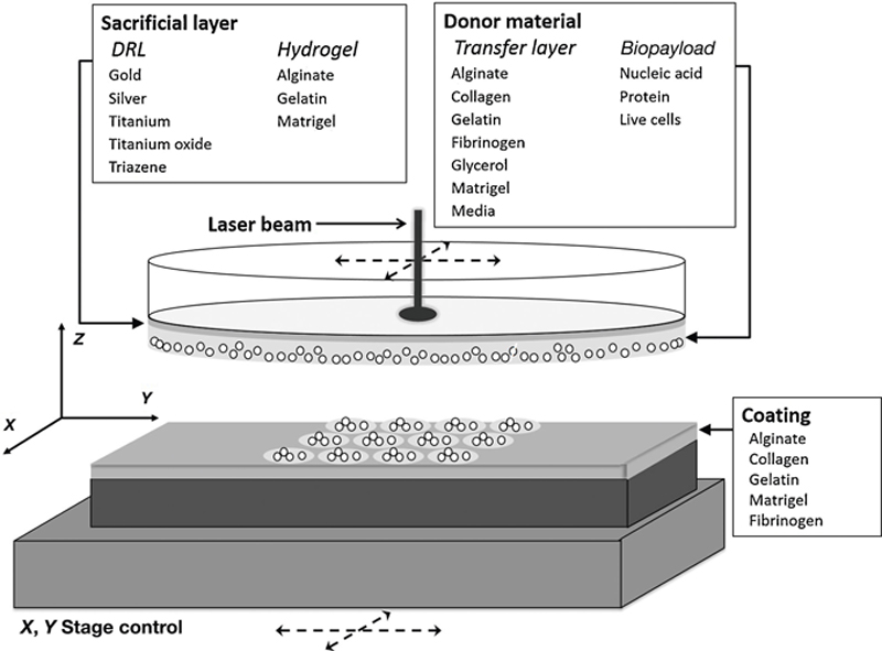
LDW is a noncontacting material deposition technique. While some differences in configuration exist, a typical LDW setup consists of two coplanar plates: a laser-transparent print ribbon, which holds the material/cells to be deposited, and a receiving substrate onto which material is printed (Figure 5.2). Both the receiving substrate and print ribbon can be independently moved with CAD-CAM-controlled stages. A charge-coupled device (CCD) camera also allows real-time visualization of the ribbon and receiving substrate. The underlying side of the mounted ribbon is coated with two thin layers, the first is a sacrificial layer, and the second a transfer layer. The sacrificial layer directly interacts with the laser, while the transfer layer consists of the actual printed material. A pulse from the laser passes through the transparent ribbon and volatilizes the sacrificial layer.
image
Figure 5.2 Schematic of typical LDW setup for material or cell deposition. A laser beam passes through a laser-transparent print ribbon to interact with material, partially volatalizing a sacrificial layer and forming a vapor pocket to eject the transfer to a receiving substrate. Independent CAD/CAM control of the ribbon and receiving stages allows programmatic deposition of material.
The consensus mechanism for deposition is that laser energy is absorbed by the sacrificial layer, forming a vapor pocket at the ribbon–material interface (Barron et al., 2004a). Expansion of the vapor pocket allows the printed material – the donor material – to form a droplet that is ejected from the surface of the print ribbon, on a trajectory perpendicular to the plane of the ribbon. It is also generally accepted that for a high-power laser and an appropriate sacrificial layer, mass transfer occurs at a much faster time scale than heat transfer (Barron et al., 2004a). Furthermore, heat shock protein expression does not appear to be elevated with LDW (Chen et al., 2006), meaning that thermal damage to the transferred material is negligible. Moreover, the laser-material interaction occurs at the surface of the material (Barron et al., 2004a; Barron et al., 2004b), so the bulk of the material that is transferred using LDW never directly interacts with the laser. After deposition, the receiving substrate is moved to the next programmed position, and a new spot is used for volatilization on the ribbon; serial deposition creates a desired structure or pattern according to the programmed stage positions. Typically, a receiving substrate is a Petri dish, cover slip, or glass slide, and is often coated with a thin layer of material that serves as the matrix material.

5.2. Materials in LDW

5.2.1. Material Properties Influencing Cellular Microenvironments

In this section, we will focus on how the materials used in LDW can affect cell response and thus be used to engineer desired microenvironments. Functional and mechanical properties of the material will determine not only how the cells interact with the substrate, but also how they interact with other nearby cells.
Mechanical properties of a substrate play a critical role in the gene expression and determination of the functional role a cell performs. As cells adhere to a substrate, they form focal complexes that become points of force transfer between the substrate and the cell. On a softer substrate, in response to a stress initiated either externally or by the cell itself, the substrate-cell attachment region deforms more than the cell. On stiffer surfaces, less deformation of the substrate interacting with the focal contact point takes place, and there is a greater stress on the cytoskeleton elements causing cell changes. Significant differences in substrate stiffness manifest in different cell morphologies, cytoskeletal reorganization, gene expression, and fate decisions. The pioneering work of Dennis Discher’s group (Engler et al., 2006) showed that mesenchymal stem cells (MSCs), when cultured on substrates of different elastic moduli, exhibited different morphologies and gene profiles; substrate stiffness could be used to direct their differentiation (Engler et al., 2006). Thus, the substrate stiffness is an important factor to consider when engineering the cellular microenvironment.
Functional groups present and their relative concentration in the ECM also play a pivotal role in the overall behavior of the cell. The presentation and binding of ligands is necessary to induce adhesion, motility, survival, differentiation, and other specific cell functions. For example, human embryonic stem cell (hESC) culture differentiation typically requires the use of a Matrigel® substrate, a hydrogel derived from mouse tumor basement membrane. However, synthetic substrates can be functionalized with the integrin ligands found within Matrigel® to support hESC attachment and growth (Liu et al., 2011). In addition to the presence of the specific functional groups, their relative concentrations also play a key role in cell behavior. Substrates modified with different surface concentrations of the arginine–glycine–aspartic acid (RGD) motif exhibit differing degrees of cellular attachment, affecting the cytoskeletal structure, its organization, and the cellular morphology (Massia et al., 1991). Another feature of engineered motifs is that binding affinity is different from that of the same motif within a natural protein, such as collagen or fibronectin. As a result, engineered substrates may have different binding kinetics than natural substrates. However, the surface-coated RGD can be engineered to contain additional peptide sequences that enhance its specificity or binding kinetics to a ligand (Petrie et al., 2006). Overall, mechanical properties of the material, such as elastic modulus, and biochemical properties of the material, such as functionalization, can have a profound influence on cells within the microenvironment.

5.2.2. Matrigel-Based LDW

Initial studies of cell printing by LDW utilized Matrigel® as a coating on the receiving substrate, as well as on the ribbon as a sacrificial layer/transfer material (Figure 5.3). Matrigel® is a soluble tumor extract comprised of an assortment of proteins, and it undergoes thermal gelation at 37°C, creating a 3D gel (Kleinman et al., 1986). There are several features that make Matrigel® a good candidate material for the receiving substrate and as a transfer material for LDW studies. Matrigel® contains large quantities of all the essential structural proteins along with many of the other proteins, proteases, and growth factors found in the basement membrane (Kleinman et al., 2005). Matrigel® has been used widely for in vitro cell culture to differentiate a variety of cells and is currently used almost exclusively as the scaffolding material for maintaining undifferentiated human embryonic stem cell culture (Xu et al., 2001). Additionally, Matrigel® provides a permanent matrix to immobilize printed material on the receiving substrate, contributing to the high pattern fidelity.
image
Figure 5.3 Materials utilized in LDW. The laser first interacts with a thin sacrificial layer, which can be either a hydrogel, or a dynamic release layer (DRL), such as triazene, metals, or metal oxides. The biologic payload is typically suspended in a transfer layer (e.g. glycerol for printing nucleic acids or proteins, hydrogel, or media for printing live cells). When printing live cells, the cells can either be attached to the material to be transferred (e.g. when using Matrigel®), or suspended in hydrogel or media in their trypisinized state. The receiving substrate typically utilizes a thin hydrogel coating as well, to provide viscous dissipation of energy.
However, despite these many benefits, Matrigel® has a number of shortcomings that may preclude or limit its use in certain applications, causing some researchers to seek alternative ribbon and substrate materials. As a transfer material, Matrigel® requires a cell-based biopayload to loosely attach to the Matrigel® matrix. Cellular attachment times vary depending on the cell type, making coculture transfers difficult and limited to adherent cell types. As an ECM-mimetic substrate material, Matrigel® has an inherent batch-to-batch variability because it is grown and extracted from a mouse tumor. This variability may be a source of inconsistencies among researchers, and can make it difficult to reproduce previous findings. Further, not all Matrigel® components are defined, and some concentrations are unknown. Without knowing Matrigel®’s exact content and concentration of proteases, growth factors, and other proteins, the amount of information that may be inferred from an experiment is largely limited. In an experiment using Matrigel®, it is impossible to know what factor or factor combination is responsible for the observed cellular behavior, since any potential influence by Matrigel®’s numerous unspecified constituents cannot be ruled out. Although Matrigel® provides a cost-effective basement membrane substitute because it is derived from mouse sarcoma cells, it could elicit an extreme immune response if implanted into the body. Moreover, extrapolating cell behavior observed on a mouse tumor extract to a human condition could be inaccurate.

5.2.3. Gelatin-Based LDW

Among the hydrogel materials explored for use with LDW, gelatin has proven quite promising. Gelatin is a natural polymer that is a reduced and degraded form of collagen. At room temperature, gelatin is a stiff gel, but at incubation temperatures (37°C), the polymer network becomes soluble. In LDW applications, gelatin is currently used both as a sacrificial and transfer material, as well as a receiving substrate (Schiele et al., 2011). As previously described, a laser pulse vaporizes the sacrificial gelatin, ejecting a droplet of cells. What is truly powerful about this approach is its exploitation of the thermally reversible properties of gelatin. On the print ribbon, exploiting gelatin’s thermal properties allows for partial encapsulation of the biopayload, giving the opportunity for a wide variety of cells and other payload to be transferred. Further, this technique does not require cells to attach to the matrix on the ribbon (as with Matrigel®), and thus allows cells to be printed in their trypsinized state. This is less traumatic to the cells because it does not disrupt the focal adhesions, thereby allowing even nonadherent cells to be printed. In addition to gelatin, it is possible to use other materials with temperature-dependent gelation or viscosity, such as glycerol (Guillemot et al., 2010), to encapsulate the biopayload for transfer. Gelatin’s thermal properties also offer unique benefits when used on the receiving substrate. Following transfer, after a brief incubation period, the gelatin on the receiving substrate is liquefied, leaving only the LDW-patterned cells. This further takes advantage of gelatin’s thermal reversibility to minimize the influence of potentially unwanted matrix factors in simple cell studies.

5.2.4. Dynamic Release Layers

A dynamic release layer on the ribbon is often used to control the material interacting directly with the laser, decoupling the laser from the transfer material. Dynamic release layers are thin, sacrificial layers of material that interact with the laser at its operational wavelength, and can amplify energy from the laser (Figure 5.3). Some example materials for this layer are triazene or a metal/metal oxide (Schiele et al., 2009; Ringeisen et al., 2008). With LDW, the size of the transferred material droplet is directly related to laser fluence. However, inconsistencies of the transfer material on the ribbon, such as uneven coating, could produce unwanted spot-to-spot variation in the pattern. The use of a dynamic release layer has been shown to help minimize the energy threshold required for transfer, and decrease the thermal impact on the transfer material (Banks et al., 2008). The other benefit of using such a dynamic release layer is that it provides a consistent material at the ribbon interface, thereby granting a more predictable laser–material interaction when utilizing a variety of transfer materials. Without a dynamic release layer, each transferred material will exhibit different transfer dynamics due to specific laser–material interactions. The use of a dynamic release layer will result in a consistent vapor pocket, independent of the transfer material. However, utilizing a dynamic release layer may impair or preclude ribbon and substrate visualization.

5.2.5. Additional Hydrogels and Hydrogel Processing Used in LDW

An extensive amount of hydrogels and hydrogel blends have been used for LDW applications. The use of a dynamic release layer has made it simple to change between different hydrogel materials on the ribbon as a transfer material for cells or other biological contents. To date, the most commonly used hydrogels as a transfer material are gelatin, Matrigel®, and alginate (Barron et al., 2004a; Koch et al., 2010; Koch et al., 2012). The same hydrogels are also commonly used to coat the receiving substrate during printing, to cushion the impact of printed cells, and to immobilize the printed spots to increase pattern fidelity. The feature that these hydrogels have in common is that they have rapid and controllable gelation properties that benefit immobilization of the biopayload. There has also been use of fibrinogen/hyaluronic acid and collagen both as transfer material and for coating the receiving substrate (Koch et al., 2012; Gruene et al., 2011a). Current research in LDW has not yet focused on customizing receiving substrate properties, which can be achieved using a combination of natural and synthetic hydrogels.
Hydrogels as substrate coating materials allow for the manipulation of both the mechanical and biochemical properties of the environment. The biochemical properties of the surface can be engineered either by using protein-based gels or grafting functional moieties into the polymer that makes up the gel. Additionally, the mechanical properties of the hydrogel are tunable by manipulating the amount of cross-linking and the relative polymer concentration. LDW applications have not yet explored this parameter space. However, nonpatterning applications have begun customizing both of these properties in hydrogels for a wide range of applications. One example of manipulation of hydrogel biochemical and mechanical properties is within alginate gels, where the elastic modulus and RGD grafting density were independently manipulated to optimize the environment for stem cell differentiation (Huebsch et al., 2010). Printed material can also be manipulated, through in situ cross-linking on the receiving substrate. Example of this include the printing of cells suspended in fibrinogen to substrates of thrombin, which after a period of incubation, forms fibrin (Gruene et al., 2011a), and the printing of alginate into a substrate of calcium, to fabricate and localize microbeads (Kingsley et al., 2013).

5.2.6. Customizable Topography of Nonhydrogel Receiving Substrates

Another means to control the receiving substrate surface properties is through the use of engineered nonhydrogel materials or scaffolds. One such example of this is electrospun nanofibrous structures. As a surface coating material, electrospun fibers can be fabricated with a variety of natural and synthetic polymers, where fabrication parameters allow for the tuning of stiffness, topography, degradation, and fiber size (Pham et al., 2006). Fibers can also be chemically treated after fabrication with desired functional units, similar to protein grafting in hydrogels. Additionally, electrospun fibers can be fabricated in such a way that they are aligned, giving cells directional cues (Schaub et al., 2013). Utilizing electrospun fiber substrates with cell printing is another way to achieve idealized microenvironments, with the addition of directing cell growth through properties of the fibers and their structural alignment. A 1-day time course of fibroblasts printed on electrospun fibers (Figure 5.4) indicates that cells maintain registry to the printed pattern. Aligned fibers appear to direct the cell elongation and migration after LDW. Printing onto substrates with topographical features enables the fabrication of unique constructs or cell studies that are difficult to perform using other techniques.
image
Figure 5.4 RFP normal human lung fibroblasts printed by LDW onto PLLA electrospun nanofiber substrates. Nanofibers are aligned on the substrate, oriented left-to-right in images. Fibroblasts (a–b) immediately after printing appear rounded in their trypsinized state, but (c–d) after one day begin to align in the direction of the electrospun fibers. Scale bars are 200 μm.

5.3. LDW Applications in 2D

LDW was first used in 2D for electronics applications (Chrisey et al., 2000). Once it was shown that LDW could be adapted for use in soft materials transfer and deposition of biologics, 2D printing of nucleic acids (Colina et al., 2005; Fernández-Pradas et al., 2004), proteins (Dinca et al., 2008), and even live cells (Wu et al., 2001) was demonstrated. These bioprinting approaches hold many promising applications, ranging from biosensors fabrication, to the creation of small grafts or biological constructs, to building spatially precise cultures for in vitro diagnostics and cellular signaling studies. Various methods for laser-based deposition have been utilized, each quite similar, but with some distinct (although often subtle) differences. In this chapter, we will group all of these methods under “LDW,” although there are different preferences in the field about the most appropriate term to use. LDW-based methods operate on the same general principle, illustrated in Figure 5.2. The major difference among the various LDW methods is their choice of energy-absorbing layers that can be used to amplify laser energy.
The purpose of using a sacrificial material is so that biologics or cells are not themselves sacrificed during a deposition event. Laser-induced forward transfer (LIFT) typically uses a metal or foil as a sacrificial layer, while matrix-assisted pulsed laser evaporation direct-write (MAPLE-DW) typically uses a biologic matrix, such as Matrigel® or gelatin. Both methods have shown success depositing multiple mammalian cell types in controlled patterns (Table 5.2). Moreover, custom configurations of cells, such as grids, lines, and sheets have been demonstrated, with unrestricted cell growth from the initial printed pattern (Figure 5.5).

Table 5.2

Examples of cell types and materials successfully deposited by LDW, illustrating the applicability and broad range of research

Cell typeRibbon material (not including laser-transparent ribbon or cell suspension)Receiving substrate materialReferences
Rat SchwannSilverGelatinHopp et al., 2005
Rat astroglialSilverGelatinHopp et al., 2005
Pig lens epithelialSilverGelatinHopp et al., 2005
Bovine aortic endothelial cells (BAEC)Metal or metal oxideMatrigel®or mediaChen et al., 2006
Human Osteosarcoma (MG 63)
Au,Ti, or TiO2
Matrigel or glycerol
Hydroxyapatite or zirconia/glycerol
Extracellular Matrix Solution
Matrigel® Extracellular Matrix SolutionBarron et al., 2004a; Barron et al., 2004b; Barron et al., 2005; Doraiswamy et al., 2006a
Rat cardiacAu,Ti, or TiO2Matrigel®Barron et al., 2004a
Mouse endothelialAu,Ti, or TiO2Matrigel®Barron et al., 2004b
Human endothelial (EA.hy926)Gold, alginate, glycerol, nano-hydroxyapatiteno materialGuillemot et al., 2010
Olfactory ensheathing cellsTiO2Matrigel®Othon et al., 2008
Human umbilical vein
endothelial cells (HUVEC)
Au,Ti, or TiO2
Gold, alginate
Matrigel®Wu et al., 2010; Gaebel et al., 2011
Endothelial colony forming cells (ECFC)Gold, hydrogel precursorHydroxyapatite, fibrinogen, thrombinGruene et al., 2011a
Mouse embryonic stem cells (mESC)
Cured polyimide
Gelatin
Matrigel®
Gelatin
Kattamis et al., 2007, Raof et al., 2011; Dias et al., 2014
Human dermal fibroblastsGelatinGelatinSchiele et al., 2011; Schiele et al., 2009
3T3 fibroblastsGold, alginateMatrigel®Koch et al., 2010
Human mesenchymal stem cells (hMSC)Gold, alginate/Matrigel®Matrigel®Koch et al., 2010; Gaebel et al., 2011; Gruene et al., 2011b
Human adipose-derived stem cells (hASC)Gold, alginateMatrigel®Gruene et al., 2011c
Mouse embryonal carcinoma (P19)Matrigel®Matrigel®Ringeisen et al., 2004
Chinese hamster ovary (CHO) cellsMatrigel®Matrigel®Ringeisen et al., 2002b
Human osteoblastMatrigel®Matrigel®Ringeisen et al., 2002b
Rat B35 neuronal neuroblast cells
Matrigel®
Triazene, Extracellular Matrix Solution
Matrigel®
Extracellular Matrix Solution
Patz et al., 2005; Doraiswamy et al., 2006b
Ovine endothelial cellsGoldPEG scaffoldOvsianikov et al., 2010
Ovine vascular smooth muscle cells (vSMC)GoldPEG scaffoldOvsianikov et al., 2010
Human keratinocytesGold, alginateMatrigel®Koch et al., 2010
Human breast cancerAlginate, gelatinGelatin, calcium chlorideKingsley et al., 2013
Bovine Pulmonary Artery Endothelial Cells (BPAEC)Matrigel®Matrigel®Schiele et al., 2009
Rat neural stem cellsMatrigel®Matrigel®Schiele et al., 2009
Mouse myoblastMatrigel®Matrigel®Schiele et al., 2009


image
Figure 5.5 Examples of cells printed by LDW, and evolution of structure over time. Array of human dermal fibroblasts (a) immediately after printing and (b) 24 h after printing, showing the evolution of cellular network structure from the initial printing positions. Contrast is adjusted to show detail. Lines of mouse embryonic stem cells (c) immediately after printing and (d) 48 h after printing, demonstrating the formation of embryoid bodies (EBs) on an unrestricted uniform substrate due to collective cellular behavior, rather than constrained growth. Bubbles in the background are artifacts of securing the substrate. Scale bars are 500 μm.
Because the substrate is generally homogeneous, following LDW, cells are free to migrate, cluster, or form structures uninhibited by geometric or biochemical restrictions on the substrate. This property of LDW allows cellular migration and migration-based behavior to be studied. By observing structural evolution, LDW enables different types of studies than what can be explored using micropatterned proteins, because patterning proteins restricts cell migration to adhesion islands. Unrestricted cell growth following LDW has been demonstrated with a Matrigel® coating on the substrate in earlier work (Wu et al., 2003; Schiele et al., 2009), and more recently with a gelatin substrate coating (Schiele et al., 2011). An advantage of the gelatin substrate is that the gelatin coating is temporary (as mentioned in Section 7.2.3), and does not provide cells with a permanent scaffold or a large assortment of unknown complex signaling factors. Thus, after the gelatin has liquefied during incubation, and is removed with the first media exchange, the cells remain attached to the underlying substrate. This allows various substrates and materials to be utilized, provided the thin temporary gelatin layer is applied to enable viable transfers. Despite the temporary nature of the gelatin layer, cells printed to the substrate maintain excellent pattern registry, moving on average, less than 6 μm from their initial location within half an hour of printing (Schiele et al., 2011). One restriction of this technique is the limitation to a flat surface parallel to the ribbon, but otherwise potentially any cell-adhesive material can be used with LDW, such as hydrogels or scaffold materials with engineered topography.
Although LDW can potentially be used to study the effects of cell location and cell-cell interaction, exploration of cellular phenomena after LDW patterning has been examined in only a few instances. One study of embryonic stem cell (ESC) behavior examined the clustering of ESCs after LDW. ESCs are pluripotent, meaning they can differentiate into any of the three primitive germ layers. It was shown that following LDW, mouse ESCs (mESCs) maintained their pluripotency, as evidenced by their ability to express markers of all three primitive germ layers (Raof et al., 2011). An additional indication of pluripotency is the formation of 3D cell clusters called embryoid bodies (EBs), which contain cells of all three germ layers. The cell–cell interactions within the EB are greatly important. The size of the EB, which may impart complex signals to cells within the structure, can influence differentiation, as can the size of a stem cell colony (Peerani et al., 2007; Bauwens et al., 2008; Lee et al., 2009b). The micropatterning approach previously used to study this phenomenon only allows the combined effect of the patterned protein and colony size to be studied. However, it would be ideal to study the effect of colony size and the surface-coated protein independently.
Controlling EB size can potentially be very useful to direct differentiation, and LDW has been used to control EB size, via the density of printed cells, independent of the stem cell colony diameter (Dias et al., 2014). While colony size did not influence the size of the EBs that formed, the effect of colony size on stem cell differentiation based on cellular patterning on a homogeneous substrate still needs to be determined. Prescribing these factors in engineered microenvironments could allow more efficient directed differentiation of stem cells. Additionally, differentiation can also be influenced by printing protein gradients, as reviewed (Tasoglu et al., 2013). The versatility afforded by LDW for printing cells, biomaterials, and proteins, enables complex studies to differentiate stem cells, influence migration, and answer many other questions using engineered microenvironments.

5.4. LDW Applications in 3D

5.4.1. Microenvironments in 3D

Planar, 2D cell culture has long been a paradigm for studying mammalian biological phenomena in vitro, ranging from stem cell differentiation and tissue development to drug testing. However, fundamental differences exist in the way cells behave between 2D and 3D microenvironments. Cells with 3D microenvironment interactions show differences in their cytoskeletal structure, morphology, membrane protein distribution, and interaction with soluble factors (Pampaloni et al., 2007). Additionally, cells cultured in a 3D ECM experience limitations for cell migration, while those grown on a 2D substrate can migrate and proliferate without the same restrictions.
In a 2D environment, cells are only able to interact and attach to the ECM on the substrate. This produces a difference in the receptor density and orientation along the surface of the cell compared with receptor orientation in 3D (Meshel et al., 2005). Further, the composition and strength of the complexes forming the adhesions differ between 2D and 3D microenvironments. As an example, on a 2D substrate, fibroblasts form adhesions along only the ventral surface (Berrier et al., 2007). The localization of cell traction forces results in a morphological polarity that does not exist in 3D. In a 3D environment, adhesion is formed via focal complexes (as opposed to 2D focal adhesions), all along the cell membrane, and has a different composition. The difference in cell distribution and type of adhesion site in 3D affects the organization and generation of tension in the cytoskeleton (Pedersen et al., 2005). The compounding discrepancy between 2D and 3D cell-matrix interactions can yield very different behaviors and response to stimuli, when explored experimentally.
In a 3D ECM, cell migration occurs either by moving through the material’s pores, or by breaking down the surrounding ECM with proteases. Highly porous materials, such as sponges and foams, typically have pore sizes greater than the cell diameter, allowing for nonproteolytic migration. In hydrogels, the pores are on the nano scale (much smaller than the actual cell). For infiltration to occur, the cell must produce proteases to break up the restrictive matrix, assuming the matrix is made from a peptide-based gel. The ease of infiltration will determine the migratory rate of the cells within the material. Additionally, the pore size will be a factor in determining the rate that nutrients can diffuse into and waste products can flow out of the bulk material. If the bulk material is too thick and/or pore size too small, toxins can build up in the environment, or cells can die due to ischemic effects.
Fundamental biological questions have been, and will continue to be solved using 2D culture models. However, 3D alternatives are necessary to overcome 2D matrix interactions that fundamentally change cell behavior (e.g. cytoskeletal structure, morphology, membrane protein distribution and interaction with soluble factors (Pampaloni et al., 2007), and focal adhesions). Additionally, the creation of large tissue-engineered constructs, for fundamental research or in vivo transplantation, will require a means of 3D fabrication with precise spatial arrangement of the contents. To overcome the limitations set by 2D environments, LDW has been adapted to build more physiologically relevant 3D culture models, in vitro diagnostic tools, and tissue-engineered constructs.

5.4.2. Layer-By-Layer Approaches

Layer-by-layer (LbL) printing is a 3D biofabrication approach adapted from industrial rapid prototyping technologies. Traditionally, LbL printing utilizes a 2D method, sequentially, to produce an overall 3D construct. After one layer is fabricated, it is often stabilized before the next layer is printed to provide a flat new printing surface. For LbL LDW, liquid hydrogel, or hydrogel precursor suspending a desired biologic, is used as a transfer material, similar to the 2D printing method. The hydrogel is deposited at preprogrammed coordinates, according to the specific layer design. Once the printed layer is completed, it is gelled by either cross-linking the polymer solution, or inducing polymerization. Gelation can be triggered by a number of different cross-linking or polymerization mechanisms (e.g. thermal, ionic, pH, or enzymatic), depending on the hydrogel or hydrogel blend. The rate of gelation for each of these mechanisms differs, and generally a fast gelation time is desired to maintain pattern fidelity. Once the layer is gelled, the printing surface is stabilized, and the process can be repeated to add additional layers until the overall construct is completed.
Another method of performing LbL fabrication with LDW utilizes a hydrogel precoated on the substrate, rather than in the transferred material. Thin-film coating mechanisms can consistently make thin layers of liquid hydrogel polymer or precursor on a substrate at a desired height. The selected material is transferred into the liquid hydrogel layer in a programmed pattern. The layer is gelled, and a new printing layer is produced by the addition of new hydrogel solution, again coated to the desired layer thickness. This technique is very similar to the previous method, but may hold advantages if each layer needs only a small amount of printed substance, relative to the overall bulk material. These techniques can be repeated for a desired number of layers. 3D resolution is determined by the hydrogel coating mechanism’s control over the height of the newly laid hydrogel layer. The average height for individual layers with one such coating technique, blade-coating, approaches approximately 40 μm (Gruene et al., 2011b). Combinations of hydrogel materials previously used in LbL LDW, as well as other candidate materials, have been listed in Figure 5.3. LbL LDW has been used for in vitro and in vivo skin tissue, an osteosarcoma model, and cardiac regeneration (Koch et al., 2012; Gaebel et al., 2011; Catros et al., 2011). Beyond creating tissue models, 3D LDW can be used to study cell-to-cell signaling. One powerful example of 3D LDW studied the coculture signaling and migration between adipose-derived stem cells and endothelial colony forming cells in hyaluronic acid and fibrin gelsu (Gruene et al., 2011a).
The LbL LDW printing technique appears to be very similar to another LbL technique, ink-jet printing, which has also been adapted for biological applications. Ink-jet printing deposits hydrogel material, which suspends cells, directly from a nozzle to a substrate, either spot by spot or by continuous flow. Discrete layers of printed material are often gelled prior to printing additional layers. The advantages of ink-jet printing include that it is generally less expensive than LDW, and offers higher throughput.

5.4.3. LDW Microbeads

Microbeads are spheroidal microstructures that can encapsulate a desired biologic, and have been investigated for applications ranging from drug delivery to cell culture (Xie et al., 2009; Amsden et al., 1997). For cell-based applications, microbeads are fabricated from cross-linkable polymers, or precursor as used for hydrogels. Like bulk hydrogels, microbeads provide cells with a 3D environment, but there are distinct advantages to the microbead structure. Nutrient diffusion into bulk hydrogels occurs slowly, and large gels may even require a bioreactor to prevent encapsulated cells from suffering from ischemic effects or buildup of metabolic waste. Microbeads, on the other hand, have a high surface area-to-volume ratio, allowing for more rapid exchange of nutrients and waste products. Further, microbeads provide greater control of the cell microenvironment, especially in studies involving multiple cell types. Properties of the individual beads can be tailored for the specific cell type, whereas bulk gels are generally isotropic.
Current microbead fabrication techniques include electrostatic bead generators, microfluidic devices, and other emulsion-based techniques (Amsden et al., 1997; Desmarais et al., 2012). These technologies operate under the same general principles to fabricate beads: cells are suspended in a polymer solution, and a single droplet is extruded into a cross-linking bath, where rapid gelation occurs to encapsulate the suspended contents. For example, in a solution of alginate with suspended cells, a droplet can be extruded into a bath containing calcium. The divalent Ca2+ cation ionically cross-links the alginate solution, causing rapid gelation, and encapsulating the suspended cells. The current fabrication technologies used to produce microbeads have certain limitations in their uses. Electrostatic bead generators limit bead fabrication to only polyelectrolyte materials, whereas other pressure- and flow-based techniques appear to have relatively consistent control of bead size, but only over a limited range. None of these technologies are able to control microbead placement.
A recently developed method for bead fabrication uses LDW to both fabricate and pattern cell-containing alginate microbeads in a single step (Kingsley et al., 2013). This LDW setup consists of a ribbon with an alginate–gelatin sacrificial layer and cell-suspending alginate transfer material. The receiving substrate consists of a thinly coated layer of gelatin/calcium chloride. A pulse from a laser ejects cell-containing alginate droplets to the substrate below in a prescribed location, where in situ gelation occurs via calcium chloride/alginate cross-linking. This technique manipulates microbead size by adjusting the diameter of the laser beam used to eject the material. Beads fabricated by this technique in our lab were consistently produced from as large as 500 μm to as small as 50 μm in diameter (Figure 5.6). Further, bead spacing in printed arrays was accurate within 2% of the desired spacing. The viability of cells encapsulated within beads remained high, very close to what is found using gelatin-based planar LDW. This work leads into ongoing research that utilizes single microbeads as “voxels” to form larger 3D structures. Microbeads are printed consecutively, layer-by-layer, on top of one another, to produce an overall 3D construct in which the architecture and composition are prescribed with microbead-level fidelity.
image
Figure 5.6 Examples of microbeads fabricated and patterned with LDW in a single step. Patterns are shown with microbead diameter sizes of (a) 150 μm, (b) 350 μm with human breast cancer cells, (c) 500 μm, and (d) multiple bead sizes in a single pattern with mouse embryonic stem cells. Scale bars are 200 μm. Bead size is controlled by adjusting the laser beam diameter, and cell density is adjusted via the cell density on the print ribbon. Microbeads can be patterned into custom configurations to study spatially sensitive aspects of the microenvironment.

5.4.4. Fabrication of Shelled Microenvironments

Microbeads have many uses for 3D cell-based applications. However, in certain circumstances where one would want the cells to produce their own scaffold material, a microcapsule may be a more ideal structure. A microcapsule is a hollow shelled spherical microenvironment, made from processing a microbead (Orive et al., 2006). In the case of an alginate microbead (negatively charged polymer), a microcapsule is formed by the addition of an oppositely charged polyelectrolyte, such as poly-l-lysine or chitosan (positively charged polymers). The oppositely charged polymer complexes with the outside of the alginate microbead, forming a shell surrounding the bead. The bulk alginate in the microbead is then liquefied by the addition of a chelating agent to remove the divalent cation that cross-links the alginate. This results in a hollow shell composed of the two oppositely charged polymers, while still retaining the encapsulated cells.
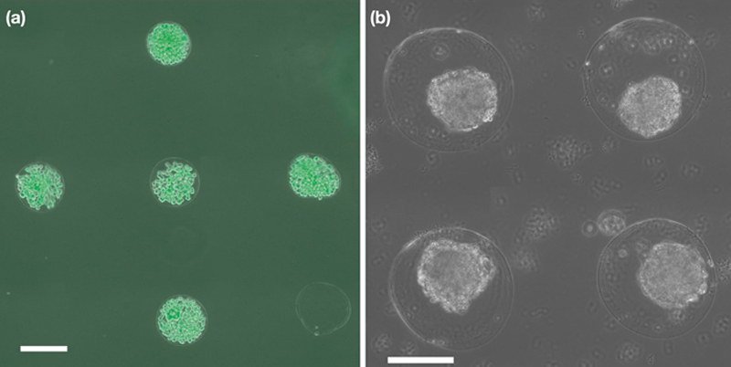
Processing of LDW patterned and fabricated microbeads to microcapsules is current and ongoing work. Figure 5.7 shows preliminary results of processed LDW microbeads into chitosan-alginate microcapsules. It appears that processed microcapsules retain initial bead position on the patterned substrate. The advantage of these capsules fabricated by LDW is that they can be placed accurately (within 2% of their target spacing). By exchanging the ribbon during printing, coculture studies can examine how signaling occurs from capsule to capsule. The spatial precision afforded by LDW allows fabrication of capsules or beads that are approximately touching. This suggests future applications where beads could be placed overlapping and processed to create hollow complex structures, or any planar geometry.
image
Figure 5.7 Microcapsules created by processing microbeads fabricated and patterned by LDW. (a) Human breast cancer cells in poly-l-lysine capsules after 7 days, and (b) mouse embryonic stem cells in chitosan capsules after 3 days, illustrate that the hollow microcapsules allow cell growth over time within a constrained geometry. The breast cancer cells grow to fill the hollow capsule, and the stem cells form an embryoid body (EB) contained with the microcapsule. The many differences between these images illustrate that the material, cell type, and other features of the microenvironment can greatly influence cell behavior. Scale bars are 500 μm.

5.5. Conclusions and Future Directions

There are some aspects of cellular behavior, such as migration, differentiation, and certain types of gene expression, that are heavily influenced by the cellular microenvironment. Both mechanical signals from the substrate and biochemical signals, either soluble or insoluble, have profound effects on cell fate and function, and are being widely studied. However, cell–cell signaling is also an important influential factor in cell behavior, yet this is rarely studied, due, in part, to the complexity and technical challenges in doing so. Therefore, it may be prudent to control how cells signal within the microenvironment. Factors that can be manipulated include whether the cellular signaling is homotypic or heterotypic, the strength of the signal based on the number/density and placement of cells, and the signaling dynamics. Herein, we have discussed patterning approaches, in particular LDW, to control cell placement in engineered microenvironments. Although it is all but impossible to mimic the sheer complexity of multiple cell types and signals in vivo, spatially precise patterning approaches onto engineered substrates offers a powerful tool to prescribe and control cellular signaling for in vitro experiments.
LDW has been used to print multiple types of cells in custom patterns, which allows the fabrication of microenvironments that can maximize (or minimize) a desired behavior based solely on cellular arrangement. Micropatterning has been used to show that cell size/shape or colony size can influence cell fates, but it generally does not allow evolution of structure. Moreover, the adhesive proteins that are patterned confound cell signaling, making it difficult to decouple the effect of the adhesive protein and the effect of cellular signaling.
While LDW offers capabilities for generating spatially precise 2D cellular microenvironments, it has even more power beyond micropatterning approaches in fabricating 3D microenvironments. Similar to ink-jet printing, LDW has demonstrated the ability to print cells and biomaterials in a layer-by-layer fashion. While the throughput of LDW is lower than that of ink-jet, it offers higher resolution, potentially allowing controlled studies of 3D cell-cell interactions in complex geometries. For 3D bioprinting approaches, in order to get sufficient height to the structure, fairly robust materials such as hydrogels are often used to ensure both cell viability within the printed construct and 3D structural integrity. Although this restriction on material configuration can help maintain construct geometry, it is also a limitation from a cellular perspective; in order for cells to proliferate and migrate, they must break down the nanoporous hydrogel, and replace it with ECM. 3D constructs have been realized using layer-by-layer approaches, but they take weeks, or even months to become fully cellularized because of the geometric restriction of nanoporous hydrogels. Despite this potential limitation, future applications could include complex in vitro tumor models, vessels, lamina, and other structures where the small attainable size is not a restriction.
Another recent method for creating 3D microenvironments using LDW is the fabrication of 3D microbeads of controlled size and placement (Kingsley et al., 2013). In contrast to traditional methods for fabricating microbeads, LDW allows fabrication and placement in a single step, via in situ crosslinking of a hydrogel. This enables cells encapsulated in the microbead to be precisely placed in 3D microenvironments. What follows is that this method allows the study of cells within a 3D microenvironment, but on a 2D substrate, which, in turn, permits high-quality imaging and analysis. This feature also makes microbead printing compatible with planar (2D) LDW, so hybrid 2D/microbead constructs can be fabricated (Kingsley et al., 2013). Hybrid constructs allow 2D cellular studies based on point sources of material or factors delivered by beads. Encapsulated cells within beads can potentially deliver factors continuously, or beads themselves could be used for delivery. Beads can serve also as nodes at precise spatial locations to direct 2D spatial migration. The true power of this technique is realized when additional processing of microbeads with a cationic polymer allows them to be shelled, and the hydrogel liquefied, leaving a macroporous capsule that allows cellular migration and proliferation within the boundary of the capsule. The macroporous structure afforded by microbead printing and capsule formation may also allow a highly cellular structure to be realized much more rapidly because cells do not have to break down matrix in order to proliferate.
While the LDW field seems to be moving in the direction of 3D patterning, the potential of 2D LDW has not yet been fully realized. As discussed, micropatterning, ink-jet printing, and LDW are complimentary cell printing techniques that offer unique advantages for particular applications. LDW is particularly well suited for applications that require spatial precision on homogeneous substrate and/or evolution of the printed structure are desired. 3D layer-by-layer and microbead printing approaches both hold promise for studying 3D cellular microenvironments, and allow a wide range of applications based on the same technology. The coming decade holds great promise for the advancement of LDW and cellular studies for tissue engineering and regenerative medicine based on 2D and 3D control of the microenvironment.

Acknowledgments

We would like to thank Nick Schaub and Dr. Ryan Gilbert (RPI) for providing electrospun fiber substrates, Dr. Yubing Xie (SUNY CNSE) for providing human breast cancer cells, and Dr. Guohao Dai (RPI) for providing normal human lung fibroblasts. This work was also supported, in part, by NIH R56-DK088217 (DTC) and DoD, Air Force Office of Scientific Research, National Defense Science and Engineering Graduate (NDSEG) Fellowship, 32 CFR 168a (ADD).