Chapter 18
Manufacture
The main structures of most small fixed-wing unmanned air vehicles (UAVs) are essentially built using fiber-reinforced plastics of some kind with the addition of foam, plywood, and metallic parts where needed. To these are assembled a whole raft of externally sourced components, which are then connected via suitable wiring harnesses. As has already been made clear in Parts II and III of this book, we have adopted the use of 3D printing (rapid prototyping) to deal with a great deal of the more complicated geometries needed in our UAVs and have limited the use of fiber-reinforced material to stock shapes that can be bought in and used with little further effort, though they still usually form the main load-bearing backbones of most of our airframes (see Table 18.1 for typical properties). We thus avoid the use of molds with glass-/carbon-fiber-reinforced plastic (GFRP/CFRP) lay-up processes completely; molds are expensive and add a layer of tooling that we no longer believe necessary, though many commercial UAVs are still produced in this way and we often manually clad our foam parts in fiber materials.
Table 18.1 Typical properties of carbon-fiber-reinforced plastic (CFRP) tubes
| Property | Units | CF fabric | CF unidirectional |
| Density | g/cm |
1.60 | 1.60 |
Young's modulus 0 |
GPa | 70 | 135 |
Young's modulus 90 |
GPa | 70 | 10 |
Ultimate tensile strength 0 |
MPa | 600 | 1500 |
Ultimate compression strength 0 |
MPa | 570 | 1200 |
Ultimate tensile Sstrength 90 |
MPa | 600 | 50 |
Ultimate compression strength 90 |
MPa | 570 | 250 |
| Poisson's ratio | 0.3 | 0.3 |
18.1 Externally Sourced Components
To hold costs down and to make the best use of economies of scale, we buy in as much of our UAVs in part form as possible. The cost savings achieved by using commercial off-the-shelf (COTS) parts can be prodigious. A good-quality aeromodeler-grade petrol engine will cost a few hundred dollars. A specialist engine from a dedicated UAV manufacturer will cost thousands, while a military-grade engine developed specifically for a particular UAV project may well cost hundreds of thousands by the time development costs have been allowed for. It is thus much more cost effective to limit one's design choices to make use of what is available off the shelf and can be simply bought in, than to try and customize everything for the aircraft in hand. And by using 3D printing we turn a whole series of custom-designed and aircraft-specific airframe parts into being externally sourced as well: we simply send our part designs as CAD files to external manufacturers with the prerequisite 3D printing facilities and they then ship back the parts we need in the quantities required, see Figure 18.1. This approach to manufacture means that on a typical UAV it is only parts made of hot-wire-cut foam and the prototype wiring looms that we make in-house; all the rest of our airframe manufacture then simply becomes an assembly operation with standard hand tools. Even the foam is produced directly from our CAD files using fully digital approaches.
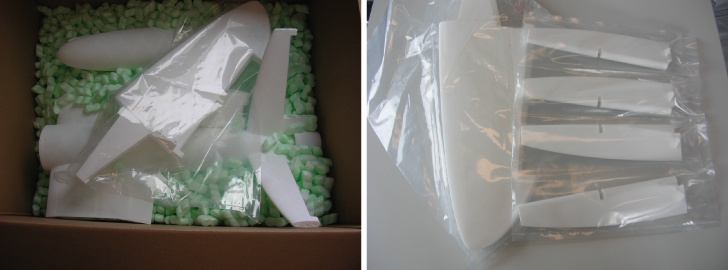
Figure 18.1 3D SLS nylon parts as supplied from the manufacturer.
18.2 Three-Dimensional Printing
We use 3D printing extensively in the manufacture of bespoke parts for our UAVs. We use selective laser sintering of nylon (for airframe parts) and of stainless steel (for highly loaded parts such as engine bearers) and fused deposition modeling of ABS for nonstructural parts where complex shaping is needed (such as for wing tips). This renders the production of parts into essentially a CAD-based design task followed by outsourced manufacture direct from the CAD files. The companies that operate such machines have a fast turn-around providing high-quality parts with very good repeatability. Figure 18.2 shows a stainless steel selective laser sintering (SLS) printed engine bearer for a gasoline engine.

Figure 18.2 3D SLS stainless steel gasoline engine bearer after printing and in situ.
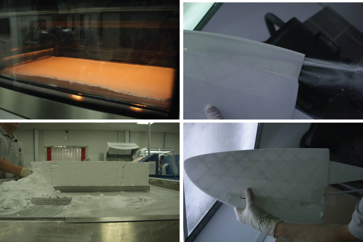
Figure 18.3 3D SLS nylon manufacturing and depowdering.
18.2.1 Selective Laser Sintering (SLS)
SLS works by fusing fine-grained powder with a laser that scans a bed of the working material. This creates a thin laminar structure. A wiper then covers the fused part with a further thin layer of powder, which is then fused to the first, thus growing a three-dimensional object layer by layer, with the parts being supported by the lower layers as they are “grown.” At the end of the print, a large “cake” of powder is left, within which lies the fused part. By removing the unfused powder (typically by suction or blowing with compressed air), the desired parts are exposed. These then need cleaning internally to remove any unwanted powder before use, see Figure 18.3. With nylon, this is all that is required. With metal SLS, it is normal to start the process on a metal base plate that must be cut off from the finished part (typically by using a wire cutting machine). In either case, the finished parts have a slightly rough surface finish that has the grain size of the raw powder. This can be removed by polishing or filling if a particularly smooth surface is required. Parts can also be colored or plated, and metal inserts can be added into the nylon. Generally we do not bother with further surface treatment for our parts. Moreover, the slightly roughened surface we find highly suitable for gluing with epoxy resins if required, either to attach parts or to carry out repairs.
When using SLS, the only limitations on design freedom are, first, it must be possible to remove any unwanted powder so fully enclosed cavities cannot be made in this way; second, there is a minimum wall thickness that can be achieved (around 1 mm); and third, the maximum size of part is constrained by the dimensions of the build chamber in the machine (currently for the machines our suppliers use to sinter nylon this is 700 mm  380 mm
  580 mm). See Table 18.2 for typical SLS nylon properties. In metal the build chambers are generally smaller (our supplier's machines have a maximum chamber size of 250 mm
  250 mm
  325 mm) but slightly thinner wall thicknesses can be achieved (down to around 0.5 mm). In either process, the build chamber in which sintering occurs is kept at a high temperature to aid the process. This means that allowance must be made for the shrinkage that occurs on cooling; our suppliers deal with this by scaling our designs before printing so that we do not have to consider the effect. It is also the case that the orientation of the part during construction has slight influences on the finished part. Curved surfaces, if not subsequently polished, show the lines where layers of powder end, for example, and there are slight variations in material properties. In general though, very high quality parts with good structural properties result, allowing highly functional components to be made.
Table 18.2 Typical properties of SLS nylon 12.
| Property | Units | Value |
| Color | white | |
| Density of laser sintered part | g/cm |
0.9–0.95 |
| Young's modulus | MPa | 1700 150 150 |
| Tensile strength | MPa | 45 3 3 |
| Elongation at break | % | 20 5 5 |
| Bulk modulus | MPa | 1240 130 130 |
| Melting point |  C C |
172–180 |
| Vicat softening temperature B/50 |  C C |
163 |
| Vicat softening temperature A/50 |  C C |
181 |
| Coefficient of thermal expansion | K  |
1.09 |
| Poisson's ratio | 0.39 |
For isotropic materials, the shear modulus  , bulk modulus
  , Poisson's ratio
  , and Young's modulus
  are related as
  ; for the tabulated values, SLS nylon is not isotropic.
18.2.2 Fused Deposition Modeling (FDM)
Since the machines required for SLS manufacture tend to be very expensive and the depowdering process can be quite messy, it can be useful to turn to alternative 3D printing technologies for nonstructural parts. We have for many years operated our own, small FDM machine for making parts up to 330 mm  100 mm
  100 mm in dimension, see Figure 18.4. In FDM, a plastic filament (generally ABS) is squeezed through a heated nozzle so that it emerges in a semiliquid form. This is then laid down onto a plastic platten in a chamber held just below the melting point of the plastic. The emerging plastic thus fuses to that already produced, and layers are built up at about 0.7 mm at a time. The major restrictions with this process is that overhanging structures can be made only if the resulting degree of overhang is limited (in practice a 45
 angle can be achieved). If a greater overhang is required in the final part (such as in an arch or circular hole), a scaffold of sacrificial material has to be inserted to support the ABS filament and then this must be removed after printing. This is a tedious and not always successful, so when using FDM we typically design the part such that a build orientation can be achieved with no significant overhangs. On the more positive side, FDM does allow fully enclosed voids to be produced provided the overhangs are controlled. We have printed double-skinned parts in this way, which are linked by internal baffles at the appropriate angles. A selection of FDM-printed parts is shown in Figure 18.5. In all cases, the parts that result are highly orientation-dependent in terms of mechanical properties, being very weak in the layer-to-layer direction. This can be overcome by using such parts in a prestressed form by including tension rods to link and compress the FDM components. The fuselage of the aircraft in Figure 18.6 is made from ABS using FDM in this way.
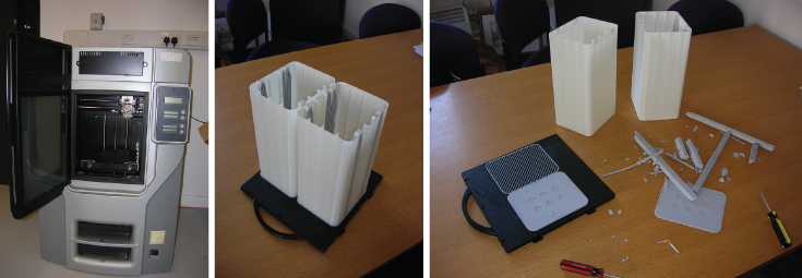
Figure 18.4 Small office-based FDM printer. Parts as they appear on the platten and after removal of support material.

Figure 18.5 FDM-printed ABS fuselage parts.
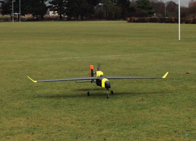
Figure 18.6 Aircraft with FDM-printed fuselage and wing tips.
18.2.3 Sealing Components
It is possible to manufacture fuel tanks using 3D SLS printing, although this makes sense only when they also form an integral part of the main structure. If nylon is used for this purpose, we find that, as manufactured, it is very slightly porous, so the finished tank must be internally sealed with an appropriate fuel-safe compound (we use Kreem Fuel Tank Liner1). Before applying the sealer, it is important that a thorough mechanical cleaning is carried out to remove any residual powder from the manufacturing process. We load the tanks with bead blasting balls and shake them well before emptying the balls out and rinsing with a degreaser.
Table 18.3 Typical properties of closed-cell polyurethane floor insulation foam.
| Property | Units | Value |
| Young's modulus | MPa | 3.64 |
| Tensile strength | kPa | 485 |
| Shear modulus | MPa | 10.1 |
| Shear strength | kPa | 391 |
| Compressive modulus in rise direction | MPa | 21.3 |
| Compressive strength in rise direction | kPa | 434 |
| Compressive modulus in in-plane direction | MPa | 10.4 |
| Compressive strength in in-plane direction | kPa | 241 |
| Poisson's ratio |  |
|
| Mean bending strength – crushing failure (as per BS EN 12089:2013) | kPa | 789.4 |
| Mean bending strength – shearing failure (as per BS EN 12089:2013) | kPa | 502.5 |
| Density | g/cm |
0.025 |
| Poisson's ratio | 0.4 |
Direction refers to the orientation during block manufacture.
18.3 Hot-wire Foam Cutting
Except for rather small UAVs, we make use of lightweight closed-cell plastic foam to manufacture most of the aerodynamic surfaces of our aircraft. This foam is cheap to buy and available in a wide range of sizes, densities, and colors. We mainly use foam blocks designed for floor insulation in the UK. This has anisotropic properties, see Table 18.3. We cut the foam using hot-wire cutting machines, one of which was manufactured in-house, see Figure 18.7, and a much larger one that was commercially sourced, see Figure 18.8. These machines work by dragging a heated stainless steel wire held in tension through the foam, melting a path just a little wider than the wire as it travels. By using suitable stepper motors to control the end points of the wires, complex aerodynamic shapes can be cut.
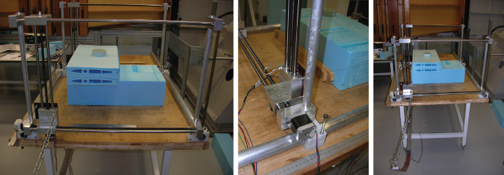
Figure 18.7 In-house manufactured hot-wire foam cutting machine. This cuts blocks of foam up to 1400 mm  590 mm
  320 mm.
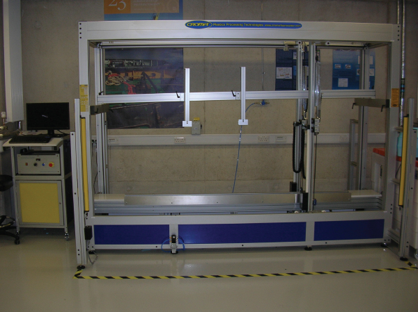
Figure 18.8 Large hot-wire foam cutting machine.
When using a hot-wire cutter to make wing parts, it is advisable to design the airfoils to have blunt trailing edges or trailing edges with a definite radius. Sharp trailing edges are difficult to cut, as the hot wire tends to melt fine edges. Holes can be cut for ribs and spars, but they must be defined so that the wire will cut in from an outer surface. Moreover, creating hollow airfoil sections can be difficult for very thin wings, as the walls of the resulting airfoil sections can be too thin, causing the wire to burn through the section. Foam cutters are also able to cut tapered geometry using different end profiles, but care has to be taken to ensure that the sections at either end line up correctly and are traversed at the correct speeds to make sure that the generated conics are as desired. There are also limitations on the maximum taper that can be cut using the machines. High levels of taper result in the wire being almost stationary at one end during manufacture, which tends to burn holes in the foam. By cutting the blocks in two orthogonal directions before removing the finished parts, all sorts of shapes can be produced. Figure 18.9 shows some typical foam wing parts and the parent blocks.
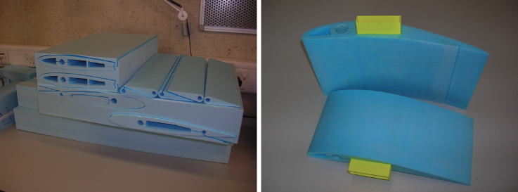
Figure 18.9 Hot-wire-cut foam wing parts: (Left) The original material blocks with and without cores removed; (right) with FDM-manufactured ABS joining parts.
18.3.1 Fiber and Mylar Foam Cladding
Although hot-wire-cut foam can be used to make very light and cost-effective aerodynamic parts, the approach suffers from some drawbacks. First, the finished surface is not perfectly smooth; second, any local loading must be fed into the foam via load spreaders to avoid local crushing damage; and third, the foam is usually not resistant to fuels of any kind. To deal with all these issues, and to provide robustness against ground handling damage, we almost always clad our hot-wire-cut foam parts after manufacture. This also significantly strengthens the foam in bending and, because it closes off the cut lines needed to make interior lightening, access, and spar holes, significantly increases torsional rigidity. We do this either by applying very fine glass-fiber or carbon-fiber tissue using thin resins or by covering the foam with sheets of heat-shrinkable aero-modeler wing film or thin Mylar attached with spray-on contact adhesives. This is one of the few remaining manufacturing tasks in our UAV builds that relies on skilled workers to produce the best results, although with a little practice and some care, cladding parts is not that difficult. If fiber tissue has been used, the resulting surface, though tough and fuel proof, is not completely smooth. This can be overcome via judicious use of fillers, but this adds weight, noticeably so on large wings. Figure 18.10 shows a selection of aircraft wings with differing forms of cladding. Table 18.4 gives typical bulk properties of glass-fiber-reinforced materials; but note that our claddings ultimately fail by delamination of the bond between the foam and the cladding and not by failure of the cladding itself. Also note that, when applying very thin glass fiber layers, the ratio of fiber to resin is lower than for thicker parts, and consequently the stiffness and strength properties achieved in our glass-fiber claddings are typically less than half the values given in the table.
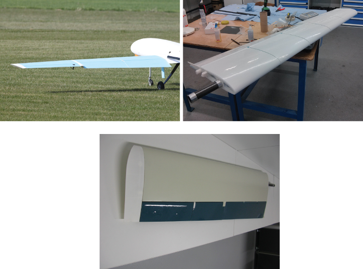
Figure 18.10 Foam wings after cladding: glass fiber, Mylar, and filled glass fiber.
Table 18.4 Typical properties of glass-fiber-reinforced plastics.
| Material | Specific gravity | Tensile strength (MPa) | Compressive strength (MPa) |
| Polyester resin (Not reinforced) | 1.28 | 55 | 140 |
| Polyester and chopped strand mat laminate 30% E-glass | 1.4 | 100 | 150 |
| Polyester and woven rovings laminate 45% E-glass | 1.6 | 250 | 150 |
| Polyester and satin weave cloth laminate 55% E-glass | 1.7 | 300 | 250 |
| Polyester and continuous rovings laminate 70% E-glass | 1.9 | 800 | 350 |
| E-Glass epoxy composite | 1.99 | 1770 | — |
| S-Glass epoxy composite | 1.95 | 2358 | — |
The composites have Young's modulus of 72–85GPa and Poisson's ratio 0.25.
18.4 Laser Cutting
Although we now almost exclusively use hot-wire-cut foam to make our wings, we have built wings using assemblies of laser-cut plywood components glued together with epoxy resins. These are then covered with thin aero-modeler-grade films, see Figure 18.11. Such wings can be extremely light and stiff, but they are rather time consuming to assemble and require some skill to achieve the best results. The film coverings can also be susceptible to ground-handling damage. Laser cutting does, however, guarantee very accurate component sets to start with. Laser cutting can also be easily applied to sheets of acrylic to form lightweight reinforcement patches. Currently we try to restrict the use of such laser-cut parts to avionics base boards, wing ribs at the ends of hot-wire-cut foam parts, servo mountings, and horn reinforcement patches, see Figures 18.12 and 18.13.
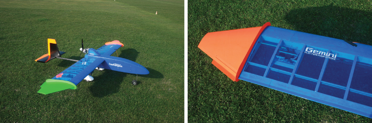
Figure 18.11 Aircraft with wings fabricated from laser-cut plywood covered with aero-modeler film.
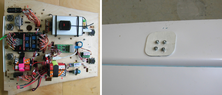
Figure 18.12 Avionics base board and servo horn reinforcement made from laser cut plywood.
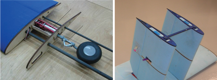
Figure 18.13 Foam reinforcement ribs made from laser-cut plywood.
18.5 Wiring Looms
As has already been noted in previous chapters, the automated manufacture of customized wiring looms is generally not affordable for low-cost, low-volume UAV manufacture. Even if a fully geometrically and functionally detailed CAD representation is prepared, assembly still requires lengths of wire to be cut and soldered to connectors, plug, sockets, and so on, by hand. This can be aided in a number of ways, however. First, a fully detailed logical wiring diagram should be prepared, which notes the color and thickness/grade of each wire in the loom. This should also show terminations and plug breaks, See, for example, Figure 18.14. Then a full-scale printed plan view drawing of the aircraft showing all parts to be connected should be printed and glued to a plywood baseboard: the so-called iron bird, see Figure 18.15. At this point, wires can be cut and compared for length to the iron bird before connectors are soldered or crimped in place. Each wire should be labeled or color-coded during manufacture.
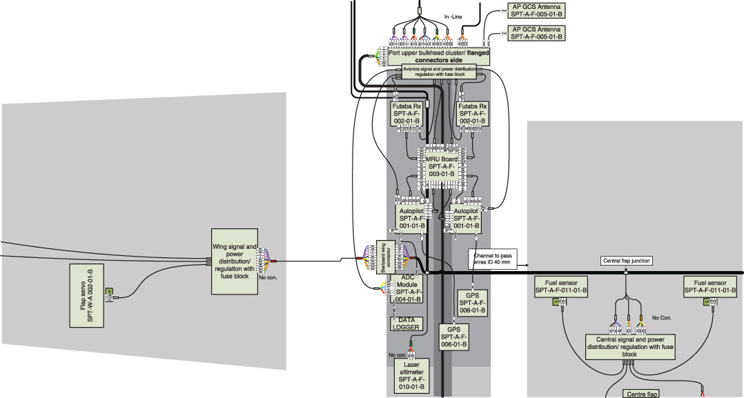
Figure 18.14 Logical wiring diagram (detail).
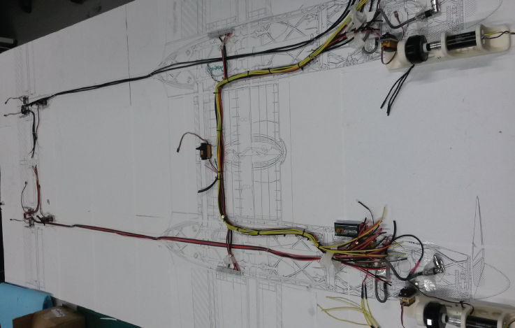
Figure 18.15 Iron bird for building wiring looms.
It is good practice to use only connectors that have an auxiliary locking mechanism to prevent disconnections being caused by accident or vibration. This can take the form of extra safety clips or connectors with built-in locks. If soldering is to be adopted, good-quality fluxed solder should be used, and the technician carrying this out should be provided with a dedicated soldering station with suitable cable holding clamps, see Figure 18.16. If crimped connectors are to be adopted, proper professional-grade crimping pliers should be used to form the crimps. In all cases, terminations should have shrink-wraps placed over exposed conductors and strain reliefs added where bulkheads will be penetrated or other chaffing or stress raisers might occur. Once terminated, each wire or group of wires can be added to the iron bird and the prototype loom gradually built up. When complete, the harness should be functionally tested by connection to all the avionics items to be fitted to the aircraft. We carry out interference and soak tests with spring-loaded servos and motor-driven generators and ignition systems on the iron bird, for example. If all is well, the loom can then be covered in cable wrap and test-fitted in the aircraft to see if any cable lengths need adjusting. At this point, either the test loom can be used to specify wire lengths and bundles for subsequent professional loom manufacture or the test loom can be finished off for flight use with permanent wraps and heat-shrink termination.
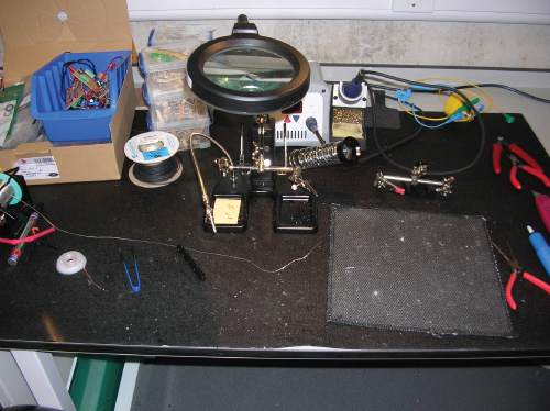
Figure 18.16 Soldering station (note the clamps, heat-resistant mat, and good illumination).
18.6 Assembly Mechanisms
By this stage, parts manufacture should be complete, and all that is required to produce the flight-ready aircraft is assembly with hand tools. Such assembly typically occurs in three phases. First, some components are assembled into the airframe structure with the assumption that they will never need removing. Second, some parts that are subsequently removed only for major service or replacement after failure, such as servos, receivers, motors, and so on, are assembled. Finally, some major components of the aircraft are usually designed to be separable for storage and transport. Thus on most UAVs it is rare to leave the wings or tail attached to the fuselage when flying is complete. These three categories of assembly tend to lead to different approaches when designing assembly mechanisms:
- Parts in the first category can be glued into place with epoxy resins or bolted in using cap-screws that are then completely inaccessible (we always apply thread-locking fluid to such screws).
- Parts that may need removal for replacement or service must be fixed with screws, threaded rods, or 3D printed clips that facilitate removal. When designing the fixings for such parts, care must be taken to allow for access with suitable hand tools such as hex-drivers for cap-screws, and so on, and to get hands in to attach cables or pipes. Sometimes it is useful to make small access holes in the fuselage parts to facilitate this; alternatively, suitable hatches must be designed in.
- Parts that must be disassembled every time the aircraft is stored or transported should ideally require very few screws to be removed. We often use tool-free locking pins and clips and bayonet systems to facilitate assembly of the main components of the airframe.
18.6.1 Bayonets and Locking Pins
Since we now routinely build our fuselages from SLS nylon, and because the build chambers in the machines available to us are of limited size, we often find it necessary to build up our fuselages from multiple SLS parts. This has naturally led us to develop bayonet joining systems that allow parts to be effectively and quickly linked. We have then made best use of this need to provide access to the interior of our airframes. The bayonets we use require a 60 twist to engage, and we then prevent them from undoing by the insertion of quick-release pins, see Figure 18.17.
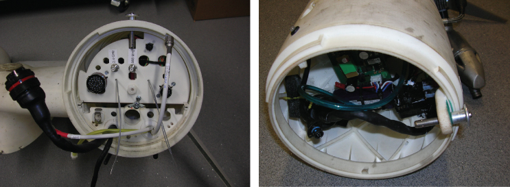
Figure 18.17 Female and male bayonet produced in SLS nylon with quick-release locking pin.
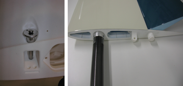
Figure 18.18 Quick-release pin fitting used to retain a wing to a fuselage (note lug on wing rib).
We often also use quick-release locking pins to secure the wings on our aircraft to the fuselage, see Figure 18.18. Here the main boom slides into a mating hole in the fuselage, and the two nylon lugs then locate in matching holes in the fuselage with one of the lugs being shaped to accept the retaining pin.
18.6.2 Clamps
To attach the main structural carbon fiber reinforced plastic (CFRP) booms and spars to our aircraft, we use clamping arrangements to avoid the need for drilling retaining holes in the parts. We find CFRP is not easily or cleanly drilled, so we avoid this where possible. Where the CFRP part is not meant for routine removal, we design such clamps to be closed with cap-screws, see Figure 18.19a. For clamps that retain wings or tailplanes, where these need to be repeatedly removed for storage and transport, we use quick-release systems so that the clamps can be undone without tools, see Figure 18.19b.
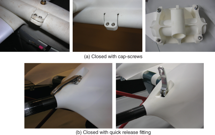
Figure 18.19 SLS nylon clamping mechanisms.
18.6.3 Conventional Bolts and Screws
To hold in parts that are not routinely being removed we make extensive use of stainless steel cap-screws and washers with nyloc nuts or plain nuts and thread-locking fluid. We often find it convenient to place the nuts in appropriately molded hexagonal holes in the SLS nylon and be retained there with cyanoacrylate glue so that only a cap-screw driver is needed to fix the bolt; it is often difficult to gain access to both ends of such screws to apply both driver and spanner, see Figure 18.20.
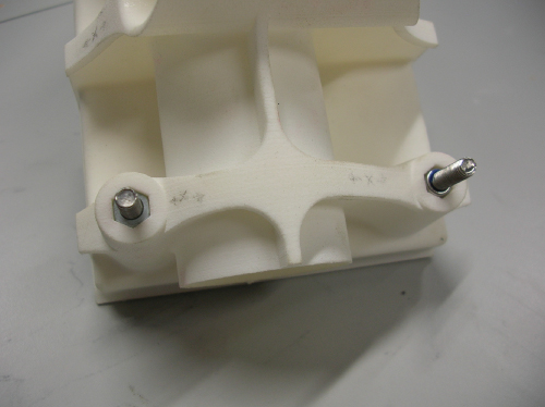
Figure 18.20 Cap-screws and embedded retained nuts, here on an undercarriage fixing point.
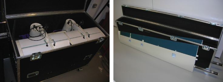
Figure 18.21 Transport and storage cases.
18.7 Storage and Transport Cases
Having assembled a new UAV that may represent a considerable investment in manufacturing cost and effort, we think it sensible to provide storage and transport cases, custom-sized to suit the airframe. Such cases are not very expensive and a number of companies around the world produce suitable items to supplied dimensions very rapidly. Ideally they should have armored corners and edges, locks, foam-lined interiors to match the airframe, and wheels and handles to facilitate handling. It is also convenient to have hinged lids with stays. Figure 18.21 shows two of our cases.