Chapter 20
Test Flights and Maintenance
20.1 Test Flight Planning
When developing a series of test flights, we first consider what we are attempting to measure and the safest order in which to carry out these flights. By definition, test flying is bound to be a higher risk activity than simple operation once all the system behaviors have been established. We always carry out initial tests at a properly controlled test airfield and with an experienced test pilot. We have for many years worked with Paul Heckles of the Paul Heckles Flight Centre.1 Paul is an enormously experienced pilot who has on many occasions managed to cope with unexpected events during flight testing and bring our aircraft safely back to the runway. He has also spent many hours helping our students learn the importance of a disciplined approach to flight testing while still making the experience a great deal of fun. Here we set out our approach to planning test flights.
20.1.1 Exploration of Flight Envelope
The most fundamental aim of test flying is to establish the safe flight envelope of the aircraft. This should, of course, be very similar to that planned for during the design process, but it is only by carrying out flight tests that this can be finally assured. There are a number of fundamental flight behaviors that must be established for all aircraft:
- 1. confirmation of center of gravity location
- 2. control response
- 3. overall performance measurement
- 4. stall angle
- 5. stall behavior
- 6. measuring lift/drag by glide testing
- 7. propulsion system behavior and endurance
- 8. calibration of pitot static system.
Some of these tests will be carried out on the ground, either with the aircraft suitably restrained or by fast taxiing tests. Once these are completed flights can begin.
20.1.2 Ranking of Flight Tests by Risk
It is of course vital that tests start with the simplest action and using only the most conservative setting of control surface deflections. Then, once the pilot and team start to gain confidence, more demanding test sequences can be attempted. We certainly would not begin to carry out any autopilot-controlled flying until an exhaustive set of manual test flights in close proximity to the pilot and in benign weather conditions had been completed.
20.1.3 Instrumentation and Recording of Flight Test Data
In all operations of unmanned air systems (UASs), it is important that good-quality logs and records are kept, see Figure 20.1 for example. This matters as much for routine operation as it does for tests during system development. Clearly, details need to be kept of airframe and engine hours to enable the specified maintenance schedule to be followed, as do details of charging cycles on any batteries that are repeatedly charged and discharged. In addition to normal pilot logs, during test flying we typically log all autopilot data to onboard secure digital (SD) cards and/or to the ground station computer for subsequent analysis. This should allow for positional and acceleration data to be logged as well as control surface inputs. We have also found it useful to attach small, self-contained video cameras to a wing tip and rudder tip so that footage of the aircraft's behavior is readily available and can be correlated against the autopilot data. Should any failure in-flight or during taxi tests then occur, it will be much simpler to understand the nature of what has happened. If the aircraft is being flown under a regulatory authority permission, this will also assist in filing any incident reports that may be needed. To coordinate all this, it is useful to designate an airframe engineering role that is distinct from the other flight team roles to ensure that suitable data is properly curated.
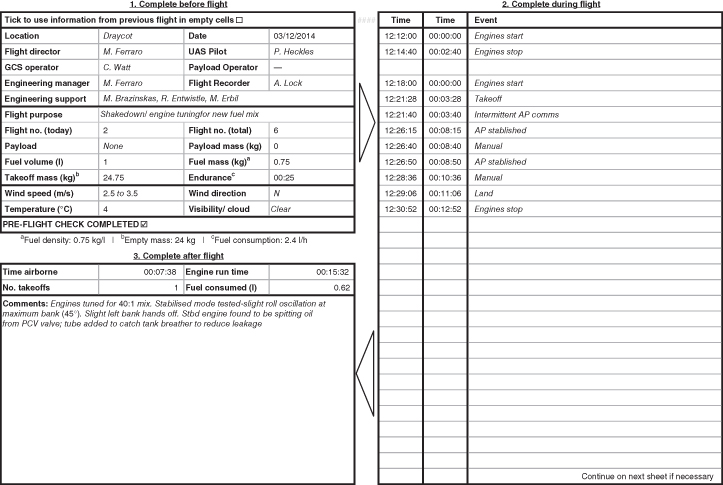
Figure 20.1 Typical flight log.
20.1.4 Pre-flight Inspection and Checklists
Before commencing any flight trials, it is important to ensure that the airfield and aircraft are all as they should be. It is now standard practice in the aviation industry to do this by way of a series of well-established and routine checklists. These should cover the following:
- 1. Departure. Checks at base carried out before even leaving for the airfield.
- 2. Post-assembly. Carried out on the airframe once it has been put together having been removed from its transport cases or hangar.
- 3. Pre-flight. The standard checks on the aircraft before each flight; see, for example, Figure 20.2.
- 4. Flight procedures. An overall list of checks that pertain to the type of test flight to be carried out; see, for example, Figure 20.3.
- 5. Site. To ensure that the airfield in use is fully understood and meets all the requirements for safe operation.
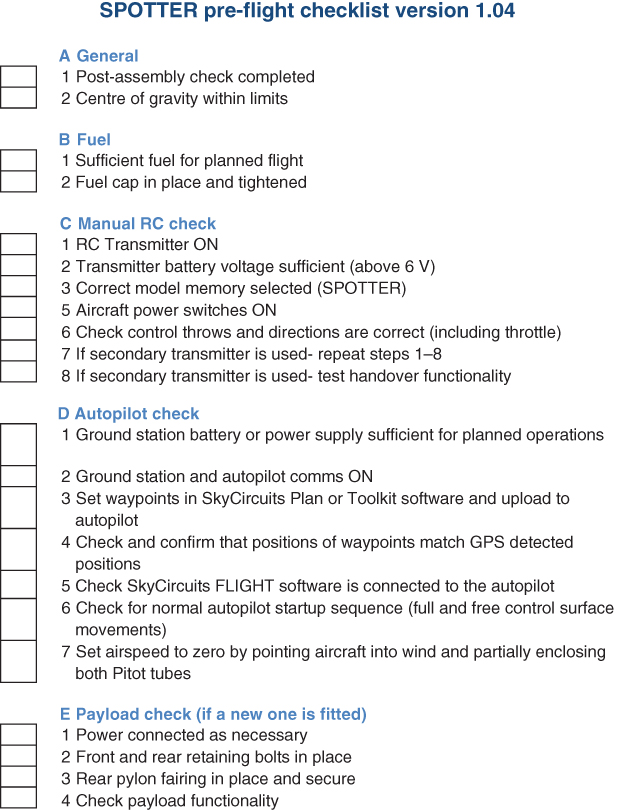
Figure 20.2 Typical pre-flight checklist.
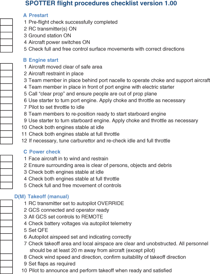

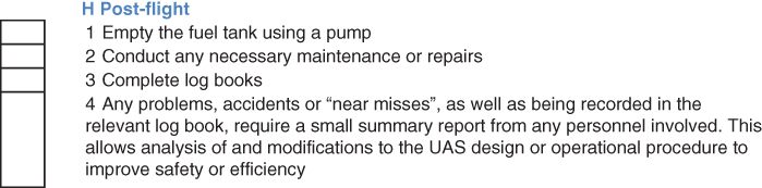
Figure 20.3 Typical flight procedures checklist.
20.1.5 Atmospheric Conditions
Atmospheric conditions play an important role in all flight operations. Therefore, before flying, suitable measurements of prevailing conditions for the flight test should be made and recorded. At the most basic level, this will be the wind speed and direction: at the very least a small hand-held anemometer should be available to the team. Pressure and humidity can also be useful in understanding engine behavior and limits on glide angle (lift and drag are of course affected by air density). The team should also have defined the worst case weather under which the test may go ahead. This should be done before reaching the flying field so that nobody is tempted to test-fly in marginal conditions.
20.1.6 Incident and Crash Contingency Planning, Post Crash Safety, Recording, and Management of Crash Site
Although every step should be taken to ensure safe and uneventful tests, it remains the case that all forms of flight can result in unplanned aircraft behavior. This can vary from brief losses in control due to radio link failures right through to crashes and the total destruction of the aircraft. It is therefore good practice to have suitable contingency plans in place along with procedures for dealing with crashes should they occur. If a sensible series of test flights have been mapped out and good safety procedures are in place, even when a major crash happens it should not lead to any injuries to people on the ground or damage to third-party structures or equipment. The whole purpose of the first few flight tests is to flush out any unexpected behavior or weakness in the aircraft in a setting that will not lead to a major incident.
If, however, a crash does occur, a known crash procedure should be invoked. Provided a thorough test program is being followed, it is most likely that such an event will lead to the aircraft impacting the ground within the perimeter of the test site and well away from those conducting the test. It is the essential that precautions are taken to deal with any hot or hazardous materials at the crash site. These will most likely be engine-, fuel-, and battery-related. Suitable fire extinguishers should be readily available and the test team knowledgeable in their use. Provided the team members are sure that there is only a very low risk of fire, attempts should be made to disconnect and isolate such items from the rest of the crash site. Photographic records should also be taken. When the team members are sure that there are no remaining hazards and all has been recorded, the debris should be gathered up and the area thoroughly cleaned. Lastly, all incidents should be written up and the relevant aviation authority contacted if the aircraft is being flown under an authority-issued permit or exemption.
20.2 Test Flight Examples
We next list a typical set of test flights for a 25 kg UAV and ground control station (GCS) capable of full autonomous takeoff, mission operation, and landing. The sequence follows the logic just set out and will provide all the information needed to complete the system description that will be used with the completed UAS.
20.2.1 UAS Performance Flight Test (MANUAL Mode)
The very first set of self-powered tests seek to assure the design team that the airframe has basic airworthiness.
- 1. Ground handling. (a) Aircraft speed and direction controllable on ground, (b) UAV can idle and remain stationary on a grass surface suitable for takeoff without intervention, (c) control can be maintained in a fast taxi situation, (d) undercarriage is serviceable, and (e) no loss of aircraft control signal.
- 2. Aircraft handling and performance at takeoff, low-speed flight, cruise, high-speed flight, and landing to a satisfactory level for the UAV pilot to continue with flight testing.
- 3. With aircraft in chosen take-off configuration with flaps at specified angle, measure the take-off run. Keep flaps in take-off (mid) position. (a) Take-off run measured, (b) take-off run to clear 10.7 m obstacle, (c) autopilot-measured average climb rate recorded within the first 5 s after takeoff, and (d) aircraft climb average airspeed measured by autopilot.
- 4. Aircraft to clean configuration. Climb to height over airfield. (a) Max. clean climb rate into wind measured by autopilot.
- 5. Straight and level clean cruise speed measured. (a) full control inputs on ailerons, rudder, and pitch, both directions. Confirm response is adequate and equal in both directions, (b) fly UAV within approach to clean stall; check full control authority, and (c) autopilot-measured air speed.
- 6. Aircraft clean max. cruise speed measured by autopilot (no flutter seen). (a) Apply suitable control inputs to confirm handling suitable.
- 7. Gliding. Clean setup over the airfield at maximum suitable height. (a) Maintain straight and level into wind, (b) autopilot-measured average descent rate, and (c) autopilot-measured approximate airspeed.
- 8. Gliding. Take-off flap set up over the airfield at a suitable height. (a) Maintain straight and level into wind, (b) autopilot-measured average descent rate, and (c) autopilot-measured approximate airspeed.
- 9. Gliding. Landing flap setup over the airfield at suitable height. (a) Maintain straight and level into wind, (b) autopilot-measured average descent rate, and (c) autopilot-measured approximate airspeed.
- 10. Steep turns. Clean setup. At safe height and suitable maneuvering speed. (a) Autopilot airspeed measured, (b) maximum angle of bank achievable at constant height level to the left at approximate autopilot airspeed and approximate autopilot measured throttle position, and (c) maximum angle of bank achievable at constant height level to the right at approximate autopilot airspeed and approximate autopilot measured throttle position.
- 11. Steep turns. Take-off flaps. At safe height and suitable maneuvering speed. (a) Autopilot airspeed measured, (b) maximum angle of bank achievable at constant height level to the left at approximate autopilot airspeed and approximate autopilot measured throttle position, and (c) maximum angle of bank achievable at constant height level to the right at approximate autopilot airspeed and approximate autopilot measured throttle position.
- 12. Steep turns. Landing flaps. At safe height and suitable maneuvering speed. (a) Autopilot airspeed measured, (b) maximum angle of bank achievable at constant height level to the left at approximate autopilot airspeed and approximate autopilot measured throttle position, and (c) maximum angle of bank achievable at constant height level to the right at approximate autopilot airspeed and approximate autopilot measured throttle position.
- 13. Stalling clean. Climb to height then maintain straight and level. (a) Autopilot height measured and (b) idle power stall into wind – stall speed and height loss.
- 14. Stalling clean climb. Climb to height. (a) Full power stall into wind – stall speed and height loss.
- 15. Stalling take-off flaps. Climb to height then maintain straight and level. (a) Autopilot height measured and (b) idle power stall into wind – stall speed and height loss.
- 16. Stalling landing flaps. Climb to height then maintain straight and level. (a) Autopilot height measured and (b) idle power stall into wind – stall speed and height loss.
- 17. Max. level speed. Climb to height away from personnel. Increase airspeed incrementally. Maximum speed measured by autopilot.
- 18. With aircraft in take-off configuration with flaps at specified angle, measure take-off run. Flaps to zero immediately after takeoff. (a) Take-off run measured, (b) autopilot average climb rate recorded within the first 5 s after take-off, and (c) aircraft climb average airspeed measured by autopilot.
- 19. If possible, take off with zero flap. Measure take-off run. (a) Take-off run measured to be, (b) autopilot average climb rate recorded within the first 5 s after takeoff, and (c) aircraft climb average airspeed measured by autopilot.
- 20. Landing with full flap setting. (a) Flap position at specified angle, (b) approach speed autopilot approximate average, and (c) measure landing run – landing touchdown to stopped recorded.
- 21. Landing with take-off flap setting. (a) Flap position at specified angle, (b) approach speed autopilot approximate average, and (c) measure landing run – landing touchdown to stopped recorded.
- 22. Landing with zero flap (a) Approach speed autopilot approximate average and (b) measure landing run – landing touchdown to stopped recorded.
Compare the predicted results with the theoretical. Are there discrepancies? Given the above results, is it safe to continue to next flight test?
20.2.2 UAS CoG Flight Test (MANUAL Mode)
The effects of CoG changes are tested.
- 1. Ground handling. (a) Aircraft speed and direction controllable on ground, (b) UAV can idle and remain stationary on a grass surface suitable for takeoff without intervention, (c) control can be maintained in a fast taxi situation, (d) undercarriage is serviceable, and (e) no loss of aircraft control signal.
- 2. Aircraft handling and performance at takeoff, low-speed flight, cruise, high-speed flight, and landing to a satisfactory level and as per previous flight test.
- 3. Move CoG to its maximum forward position. (a) CoG correct and predicted at specified fraction of chord from leading edge, and (b) known mass added at specified forward location.
- 4. Aircraft handling and performance at takeoff, low-speed flight, cruise, high-speed flight, and landing to a satisfactory level and as per previous flight test.
- 5. Move CoG to its maximum rearward position. (a) CoG correct and predicted at specified fraction of chord from leading edge, and (b) known mass added at specified rearward location.
- 6. Aircraft handling and performance at takeoff, low-speed flight, cruise, high-speed flight, and landing satisfactory as per previous flight test.
Did the UAV fly suitably and as predicted?
20.2.3 Fuel Consumption Tests
The fuel consumption is measured for standard flight modes.
- 1. Ground handling. (a) Aircraft speed and direction controllable on ground, (b) UAV can idle and remain stationary on a grass surface suitable for takeoff without intervention, (c) control can be maintained in a fast taxi situation, (d) undercarriage is serviceable, and (e) no loss of aircraft control signal.
- 2. Aircraft handling and performance at takeoff, low-speed flight, cruise, high-speed flight, and landing to a satisfactory level and as per previous flight test.
- 3. Standard flight profile. This will consist of manual takeoff, manual circuit pattern, and manual landing. Flight duration typically to be 30 min unless limited by regulatory requirements or tank size. Throttle back to low speed. Land, checking that engine gives normal throttle response at all times. Repeat process as needed, refueling and recharging batteries when necessary. Inspect airframe as required in accordance with maintenance schedule.
20.2.4 Engine Failure, Idle, and Throttle Change Tests
Engine reliability is checked for a range of throttle settings and operations.
- 1. Ground handling. (a) Aircraft speed and direction controllable on ground, (b) UAV can idle and remain stationary on a grass surface suitable for take-off without intervention, (c) control can be maintained in a fast taxi situation, (d) undercarriage is serviceable, and (e) no loss of aircraft control signal.
- 2. Aircraft handling and performance at takeoff, low-speed flight, cruise, high-speed flight, and landing to a satisfactory level and as per previous flight test.
- 3. Standard flight profile. This will consist of manual takeoff, manual circuit pattern, and manual landing. Flight duration to be at least 15 min to ensure engine conditions reach full operating temperature. Throttle back to low speed. Land, checking that engine gives normal throttle response at all times. Repeat the process three times to ensure consistency, refueling, and recharging batteries as needed.
- 4. Simulated power loss in level flight. The test should not be attempted unless it is safe to do so and can be done in any order. The type of power loss, full or partial, should be stated at the discretion of an authorized Flight Test Director in the form of “Full Power Loss.” The UAV pilot will then cut the throttle to the UAV. (a) Port engine partial completed safely, (b) port engine full completed safely, (c) starboard engine partial completed safely, and (d) starboard engine full completed safely.
- 5. Simulated power loss after takeoff. This should be carried out at three heights. The tests should not be attempted unless it is safe to do so and can be carried out in any order. The type of power loss full or partial should be stated at the discretion of an authorized Flight Test Director in the form of “Full Power Loss.” The UAV pilot will then cut the throttle to the UAV. (a) Height 1 should require the UAV to land ahead within a 45
 arc. This should be demonstrated and a go-around commenced. (i) Port engine partial completed safely, (ii) port engine full completed safely, (iii) starboard engine partial completed safely, and (iv) starboard engine full completed safely. (b) Height 2 should require the UAV to turn back to the airfield and land downwind. This should not be attempted in wind conditions where the pilot deems this to be unsafe. This should be demonstrated and a go-around commenced. (i) Port engine partial completed safely, (ii) port engine full completed safely, (iii) starboard engine partial completed safely, and (iv) starboard engine full completed safely. (c) Height 3 should require the UAV to complete a mini-circuit and land. (i) Port engine partial completed safely, (ii) port engine full completed safely, (iii) starboard engine partial completed safely, and (iv) starboard engine full completed safely.
20.2.5 Autonomous Flight Control
The ability of the autopilot to control the aircraft satisfactorily is tested next. REMOTE refers to an aspect of GSC having been passed to the conventional pilot transmitter which can be in MANUAL or AUTO mode where AUTO refers to control by the GCS. Note that in AUTO mode unselected functions can still be manually controlled by the pilot's transmitter by setting it to REMOTE mode. Also the autopilot we use offers an ASSISTED mode where stick actions on the pilot's transmitter are interpreted as directional and speed commands rather than as servo settings (effectively, a “fly-by-wire” approach): not all autopilots offer this functionality.
- 1. Check UAV failsafe positions are correct and receiver's failsafe to AUTO MODE.
- 2. Check, with the transmitter off, that the GCS can still control the UAV.
- 3. GCS in REMOTE mode.
- 4. Transmitter in MANUAL mode.
- 5. Takeoff.
- 6. Climb to suitable height.
- 7. Transmitter to AUTO mode.
- 8. Bank. (a) Input bank command to wings level while in straight and level flight, (b) bank to GCS AUTO. Remaining controls by REMOTE, (c) pilot to maintain straight and level flight, (d) determine correct coefficients to ensure correct, stable, and non-oscillatory aircraft response: this will be achieved by setting various bank angles to be maintained and entered up to 30
 and observing aircraft response, (i) Kd established and (ii) Ki established. (e) Return bank to REMOTE control.
 - 9. Elevation. (a) Input elevation angle of zero while in straight and level flight, (b) elevation to GCS AUTO. Remaining controls by REMOTE, (c) pilot to maintain straight and level flight, (d) determine correct coefficients to ensure correct, stable and non-oscillatory aircraft response: this will be achieved by setting various pitch angles to be maintained and entered up to 20
 and observing aircraft response, (i) Kd established and (ii) Ki established. (e) Return elevation to REMOTE control.
 - 10. Altitude. (a) Input altitude to current height while in straight and level flight (at say 95 m), (b) altitude to GCS AUTO. Remaining controls by REMOTE, (c) pilot to maintain straight and level flight, (d) determine correct coefficients to ensure correct, stable and non-oscillatory aircraft response: this will be achieved by setting various altitudes to be maintained and observing aircraft response, (i) Kd established and (ii) Ki established. (e) Return altitude to REMOTE control.
- 11. Airspeed. (a) Input airspeed to cruise airspeed while in straight and level flight (at given cruise speed), (b) airspeed to GCS AUTO. Remaining controls by REMOTE, (c) pilot to maintain straight and level flight, (d) determine correct coefficients to ensure correct, stable, and non-oscillatory aircraft response: this will be done by setting various airspeeds within the safe operating range for the aircraft setup to be maintained and observing aircraft response, (i) Kd established and (ii) Ki established. (e) Return airspeed to REMOTE control.
- 12. Coefficient check by orbiting a specified waypoint. Observe aircraft response and modify coefficients as required including navigation linked coefficients. (a) Set orbit command in GCS. Bank to AUTO. Remainder in REMOTE. UAV to orbit waypoint via bank only. Check suitable aircraft response. Vary bank angles. (b) Set airspeed to maintain in GCS. Airspeed to AUTO. Remainder in REMOTE. UAV to orbit waypoint via bank and airspeed. Check suitable aircraft response. Vary airspeeds. (c) Set altitude to maintain in GCS. Altitude to AUTO. Fully autonomous control. Vary heights.
- 13. Maintaining autonomous control. Set a new waypoint to navigate to with a large separation distance with cruise airspeed and safe height. Check aircraft exhibits correct response.
- 14. Set a waypoint circuit pattern to check coefficients and turn anticipation. Check aircraft exhibits correct response.
- 15. Test-ASSISTED mode. UAV pilot to take full ASSISTED mode and check correction functionality and response UAV responds correctly.
- 16. Test of safety radius. Reduce safety radius to 200 m. When in ASSISTED mode, fly deliberately toward this outer radius. UAV should orbit the ERP waypoint when radius exceeded (the same response happens in fully auto mode). (a) UAV responds correctly, and manual control is regained after at least two orbits of the ERP are completed and (b) return safety radius to 500 m.
- 17. Check the functionality of the autopilot flight envelope. (a) Assisted mode. Envelope tested successfully, and (b) auto mode. Envelope tested successfully.
- 18. Check communication waypoint return. Over airfield with communication loss time set to 5 s. Ensure emergency waypoint is located correctly. (a) Set UAV to orbit a waypoint away from the emergency waypoint. With RC TX in full AUTO mode, disconnect GCS transceiver on laptop by disconnecting the appropriate cable. (i) After 5 s, UAV moves to emergency waypoint and orbits correctly – on success pilot to override, Reconnect GCS, (b) On successful connection with AP from GCS, fly UAV in ASSISTED mode. (i) After 5 s UAV moves to emergency waypoint and orbits correctly – on success, pilot to override, reconnect GCS.
- 19. Pilot to land the UAV in manual mode.
Is the UAS flight control system (FCS) set up correctly and did it demonstrate correct control and operation of the UAV?
20.2.6 Auto-Takeoff Test
The ability of the autopilot to carry out auto-takeoff is tested.
- 1. On each occasion, the autopilot start-up mode should be completed with all control surfaces deflecting and autopilot control initialized (check on first flight and when subsequently powering on the UAV).
- 2. GCS operator to set waypoints such that the aircraft will take off and climb out into wind.
- 3. UAV pilot to perform manual takeoff along planned path to confirm correct handling of aircraft. Land.
- 4. Aircraft to be taxied into the take-off position. Autopilot to control one channel as agreed between UAV pilot and GCS operator. Partially auto take-off and climb out followed by manual landing.
- 5. If satisfied, this is to be repeated with the autopilot progressively being given more control in an order agreed between the UAV pilot and GCS operator.
- 6. If satisfied, a fully auto-takeoff is to be completed followed by a manual landing.
20.2.7 Auto-Landing Test
The ability of the autopilot to carry out auto landing is tested.
- 1. On each occasion, the autopilot start-up mode should be completed with all control surfaces deflecting and autopilot control initialized (check on first flight and when subsequently powering on the UAV).
- 2. GCS operator to set waypoints such that aircraft will approach and land into wind.
- 3. UAV pilot to perform manual takeoff and landing along planned path to confirm correct handling of aircraft.
- 4. GCS operator to set landing script to perform a series of “simulated approaches,” whereby the aircraft will approach and flare at a specified altitude directly above the intended touchdown waypoint. UAV pilot to override control upon autopilot flare or sooner if aircraft deviates from the intended flight path. To be repeated as many times as necessary, with altitude being incrementally decreased as agreed by UAV pilot and GCS operator. On each occasion, check that the altitude control is suitably accurate. Completed successfully.
- 5. Auto landing to be performed if satisfied. UAV pilot to take control upon touchdown, or sooner if aircraft deviates from the intended approach.
20.2.8 Operational and Safety Flight Scenarios
The use of the GCS to command the aircraft to carry out various flight missions is tested.
- 1. Standard flight profile. This will consist of manual takeoff, manual circuit pattern, and manual landing. The orbit points shall move a minimum of two times to demonstrate effective operation. Land.
- 2. Standard flight profile. This will consist of manual takeoff, assisted FCS control circuit pattern, and manual landing. The orbit points shall move a minimum of two times to demonstrate effective operation. Land.
- 3. Standard flight profile. This will consist of manual takeoff, autonomous circuit pattern, and manual landing. The orbit points shall move a minimum of two times to demonstrate effective operation. Land.
- 4. Simulated loss of GCS control (laptop crash) while the UAV is in autonomous mode. Simulated by USB to aerial being disconnected.
- 5. Emergency landing. In the event of a transmitter failure, the UAV should be able to be landed using only the FCS. This should be demonstrated until it is clear that the UAV will land in the designated area. Manual control will be taken, and aircraft will perform a go-around. Control will be taken by the UAV pilot using the autopilot override switch on his discretion of this being demonstrated. No persons should be endangered. This should be fully understood before commencing test. Persons should be kept to safe area. (a) Fly UAV at height in AUTO mode with REMOTE control by pilot, (b) on close communication between pilot and GCS operator, (i) pilot to stop inputs to transmitter, (ii) wait 2 s to simulate a reaction time, and (iii) GCS to recover the aircraft and land the aircraft under the close supervision and authorization of the pilot. (c) Pilot to take manual override control when he is happy that the aircraft would land in the specified field and commence a go-around.
- 6. Landing site becomes unavailable. A nearby different location is to be chosen and an approach to land commenced followed by a go-around.
20.3 Maintenance
UAS maintenance is of vital importance to their safe operation. This broadly falls into two areas: the actual hardware that flies, and any software used both on and off the airframe in order for it to operate. Specific documented action should be taken to ensure that both hardware and software are properly maintained. For hardware, it will be obvious that the flying airframe operates in a harsh environment subject to large acceleration and deceleration forces, changes in temperature and humidity, and significant vibrations. In addition, various fuels and oils will be in use and may be spilt onto the airframe or its systems. For software, the chief dangers are undetected bugs in flight critical software either being present from the outset or being inadvertently introduced either by firmware upgrades or during operator-based programming of those functions that are designed to be set by the flight team.2
20.3.1 Overall Airframe Maintenance
It should go without saying that it is good practice when dealing with any airframe to be neat and tidy and to keep the airframe clean and to ensure that no small items are accidentally lost inside fuselages, nacelles, wings, and so on. Before flying, the appropriate logs should be checked to see if any items on the airframe are nearing the end of a service interval, which they may reach during the planned operations. All structural elements should be inspected and main spars gently flexed to ensure that all parts remain correctly attached and aligned. All flight control surfaces should be inspected for damage and moved through their full range of movement using the hand-held pilots transmitter (and not by manually forcing the surfaces – this can damage both the surface and the control servos that operates it). After every flight, the aircraft should be wiped down and any oil or fuel residues removed from the outer surfaces. If flying is completed for the day, fuel tanks should be drained before the airframe is transported.
20.3.2 Time and Flight Expired Items
A number of items on the airframe will have either time or number of flight limits on them before they should be serviced or replaced.
Engine Servicing
Most obviously, any internal combustion (IC) engine will need regular servicing by appropriately trained staff closely following the manufacturers' manuals. We carry out minor services such as valve clearance adjustments ourselves but prefer to use specialist companies for major overhauls. It is very easy, for example, when using four-stroke IC engines with very small valves to reach a situation where the exhaust valves are not seating correctly. If an engine is flown in such a condition, it is possible for very rapid valve seat wear to occur and the engine to fail in flights as short as 10 min duration. On a single-engine aircraft, this might lead to the total loss of the airframe.
Servos and Control Surfaces
Control surface servos are the next most obvious items that can suffer significant wear during flight. Consequently, we tend to replace these after specified numbers of flying hours. If one is using aero-modeler-grade items, or if the servos are very heavily loaded, they should probably be replaced at intervals of 10 h or less. Certainly, no servo should be used beyond 100 h flying time, even if only very lightly used. The attrition of on-board vibration can of itself lead to the gradual degradation of any complex electromechanical part. Attention should also be paid to the linkages and hinge points that are used to locate all control surfaces. It is very easy to accumulate wear in any bearing surfaces that will gradually allow play in the control mechanism, which will make flight control less easy and can induce control surface vibration and flutter.
20.3.3 Batteries
Airframe batteries will either be ground-charged on maintained by on-board generators. For batteries that are being ground-charged, good-quality charging systems should be used that monitor individual cell voltages during charge and control the overall current and voltage values. Charging should be carried out in appropriator locations and logs kept of the amount of charge added to a battery and the time taken to achieve this. Even the best quality LiFe, LiPo, and NiMHy batteries do not last for ever, and so after a given number of charges such items should be replaced. We would advise not recharging any airframe battery more than 50 times before it is recycled. It is also good practice to not allow airframe batteries to become too depleted unless safe recovery during a flight requires it. It is much wiser to stop a flight early or have sufficient excess capacity to ensure that batteries never go below 30% remaining charge.
When using batteries maintained by on-board charging circuits, it is tempting to almost “fit and forget” these items since the intention is that they are never heavily depleted and, moreover, have their status continually monitored by the charging circuits. However, on-board-charged batteries are typically much smaller than those that have to have sufficient capacity for the entire flight at the outset. Then, if there is any interruption to the charging circuit, they can very rapidly discharge. Thus such systems should be used only if ground-based monitoring of the battery charge is possible. Moreover, when not being flown, such batteries need just as careful maintenance as those that are routinely removed for ground-based charging.
All batteries should be periodically subjected to visual inspection to check that there is no damage or distortion to the external casing or connections. Slight bulging of the case is often the first sign of distress in a battery. Any battery with a less than perfect outer case should not be flown.
20.3.4 Flight Control Software
Flight Control Software is split into that on the airframe and that on the GCS. It will consist of firmware that is rarely changed and is largely independent of the aircraft, and operator-set software that may be readily edited and is aircraft-specific. Maintenance of firmware mainly consists of ensuring that the set in use is up to date as confirmed from the manufacturers' Web sites. If such software is updated, great caution should be taken when next flying the aircraft, just in case some unexpected glitch or feature change has been introduced. For systems that are subject to regulatory approvals, such a change may well require a reapplication for permission to fly with suitable justification for the change and evidence that it has been suitably tested.
User-programmable software is generally configured into the GCS before the beginning of each flight session and uploaded to the airframe when the avionics are first powered up. Assuming that the links between the GCS and airframe are functioning as designed, maintenance essentially involves ensuring that the correct set of software is being used and that no unauthorized changes have been made to this since it was last used. An essential part of the first test flights of any new aircraft will be the adjustment of the pilot's hand-held transmitter settings to match the characteristics of the airframe. A good deal of this will be carried out during ground tests, and a safety run through these setting will be needed before every flight to ensure that the main flight control surfaces and propulsion system behave as expected. It is good practice to then keep back-ups and records of these settings so that at the start of flying the transmitter software is in a known condition.
A similar set of parameters will also be need to be established for any autopilot fitted to the airframes. This will primarily involve the controller gain settings but also calibration of pitot tubes and the on-board magnetometer if fitted. Again, once a safe set of parameters has been established, these should be backed up and recorded so that known conditions are established before flying. In all cases, adjustments to transmitter or autopilot settings should be made only by experienced and authorized members of the flight team.
20.3.5 Maintenance Record Keeping
It will be clear from what has already been set out in this chapter that good record keeping is of vital importance to the safe operations of any UAS. This is just as important with regard to maintenance logs as it is to flight logs. The operating team simply has to be sure of the condition of the hardware and software in use to be able to have confidence in it. Such logs should be neat and tidy, readily to hand, and updated after each flight or at the very least after each flight day. Each UAS should have its own dedicated set of logs, and these should be backed up with paper hard copies that are available on the flying field.