Chapter 21
Lessons Learned
We have been building and flying small fixed-wing unmanned air vehicles (UAVs) since 2008. Figure 21.1 shows our very first student-designed and -built airframe. Since that time, we have built some 30 further aircraft and our methods of working have evolved as we have discovered the best ways of getting our designs into the sky, not always successfully, Figure 21.2.

Figure 21.1 Our first student-designed UAV.

Figure 21.2 Not all test flights end successfully!
Perhaps the most important single lesson we have learned is that good-quality detail design is of paramount importance. Even the very best concepts will be spoiled by poor detailing, while even quite poor concepts will often perform acceptably if all the detail design work is of good quality. Initially, this attention to detail also extended to the skills needed to carry out aircraft manufacture. The airframe in Figure 21.1 involved much labor-intensive construction using typical aero-modeler-type approaches with wings covered with aero-modeler film and glued wooden fuselage construction. Now, however, following our commitment to digital manufacture, this mainly concerns detail CAD-based design work backed up with appropriate simulations of the underlying physics and the mechanisms being deployed. It is thus very important that a well-rehearsed approach to the detail design phase and the supporting analyses and tests that go with it be deployed. One of the key reasons for writing this book was to ensure that our student teams be aware of these things from the outset of their project work.
Next, we would point out the importance of experiments and test flights. It is often the case that building a Mark 1 airframe early on in a project, so as to gain information that can inform a Mark 2 version, is a better approach that committing too much effort to analysis that may be of limited fidelity or based on incorrect assumptions. It is also almost impossible to get every thing “right first time,” even in the most sophisticated design organizations. Early prototypes can be invaluable in improving detail design work.
Thirdly, we would re-emphasize the critical importance of weight and center of gravity control and their impact on stall speed, pitch stability, and take-off and landing velocities. Once the wings have been sized, any increase in weight leads inexorably to an increase in stall speed and thus worsens take-off and landing performance. Such weight increases over the design weight budget stem from two main areas: first, it is all too easy to neglect vital components when making weight build-up assessments (in particular, wiring and servo linkages are often much heavier in total than one might image); second, there is always the temptation to add things; in particular, when designing the structure, it is easy to add small strengthening and stress-relieving elements without being fully aware of their total impact on weight. At all times one should be looking for places that are overly strong and removing weight, rather than just worrying about areas that are too weak and adding to them. Provided sensible sized spars are in use and basic stress analysis has been carried out, in our experience small UAV airframes are generally too strong. In all our work, we have only ever had one flight-critical structural failure and that was due to poor manufacturing and not to poor design or analysis. It is also wise to allow for some internal heavy items such as batteries to be moved forward and aft in the airframe without major redesign. This allows fine-tuning of the longitudinal center of gravity and thus control of the static margin. If there is great uncertainty about the longitudinal center of gravity position during the early stages of design, it is sensible to design the fuselage in a modular manner so that its length can be changed. We have even built aircraft where the fuselage length can be changed depending on the payload being deployed, see Figure 21.3. On smaller aircraft, it is sometimes possible to arrange for the main wing attachment point to be adjustable to achieve the same effect.

Figure 21.3 Aircraft with variable length fuselage. (a) Fuselage split open. (b) Spare fuselage section.
Fourthly, we note that if a very conventional type of airframe is to be produced, then simply following previous satisfactory design concepts will likely ensure a successful outcome. Perhaps the best place to start is with the choice of payload, powerplant, and overall airframe topology. It is only when the designs become more radical or extreme performance is required that the full gamut of well-established aeroengineering calculations become critical. That is not to say that such calculations should not be carried out for all projects; rather it is to point out that by following a previous well-designed example, much of the knowledge accumulated over the last 100 years of flight will implicitly be embedded in the new design. However, when it comes to making any calculation, we would emphasize that the care that goes into the calculation should be related to how important the result is, not how technically difficult the calculation is. So, such simple but crucial calculations as the choice of wing area should be checked and double-checked before they are accepted by the design team. One does not want to get to the airfield before it dawns on one that the wings are out of proportion to the rest of the airframe (see below)!
Good team working is, of course, also vital to any project undertaken by more than a single individual. Good teams need a mix of both personal and technical skills. Not everyone can be the team leader and many engineers are not good at such roles. Equally, it takes a particular sort of mindset to carefully and relentlessly control weight growth in a project. It is also not wise to form a team comprised of 10 aerodynamicists, just one structural engineer, and no avionics experts. As in all aspects of aircraft design and manufacture, balance is crucial.
Finally, and by no means least importantly, always carry out initial flight trials at a properly controlled test airfield and with an experienced test pilot. As already noted, we have for many years worked with Paul Heckles of the Paul Heckles Flight Centre.1 If your test pilot is not of the first grade, then any unexpected behavior is likely going to lead to a major crash and total loss of the airframe.
21.1 Things that Have Gone Wrong and Why
We have learned these lessons the hard way: over the years we have had a number of “uncontrolled descents,” mostly of student-designed and -built aircraft (but not always). We try not to intervene too strongly into our student groups during their project work since we find they tend to learn more if allowed to make their own mistakes. What follows is a list of some the things that have gone wrong and why – it is a bit of a rogue's gallery but we would not pretend that we only ever make perfect aircraft at the University of Southampton:
- A failure to ensure a positive static margin led to an aircraft taking off and immediately stalling during a fast taxi test (this occurred when a test was being carried out without Paul being present).
- A failure to ensure dynamic stability led one aircraft to exhibit uncontrollable Dutch roll. This was a flying boat and the very large area of hull forward of the aerodynamic center needed a far larger vertical tail volume than is normally required on conventional aircraft, see Figure 21.4 (note that an XFLR5 analysis would not have revealed this since XFLR5 does not model fuselage side forces).
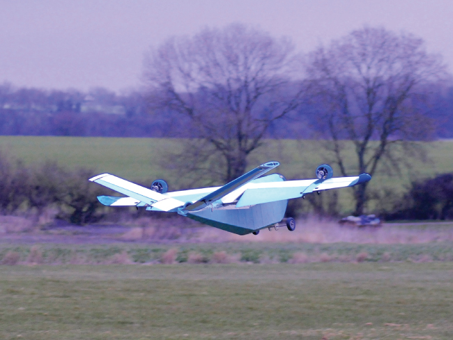
Figure 21.4 Student-designed flying boat with large hull volume forward and insufficient vertical tail volume aft.
- A failure to ensure that a set of laser-cut plywood spar parts had been correctly placed in the clamping jig during manufacture led to a main spar failure during extreme maneuvers. A simple spar load or ground vibration test would have revealed this, but neither was carried out prior to flight.
- An engine failure on a single-engine aircraft meant that the aircraft did not have sufficient height to glide back to our test runway, leading to a controlled ditching in the adjacent field. The low-speed screw on the carburetor was poorly set, and when opening the throttle rapidly from idle, the engine stalled.
- The adoption of a radical, all-steerable and split elevator on a research aircraft had a highly nonlinear impact on controllability, causing the aircraft to suddenly nose-dive on a steep turn into toward final approach, see Figure 21.5. The aircraft had previously appeared to have benign characteristics. One should always fully explore the envelope with sufficient altitude to maximize the chances of recovery from such mishaps. The rebuilt aircraft has a fence at the elevator split, which mitigates this problem.
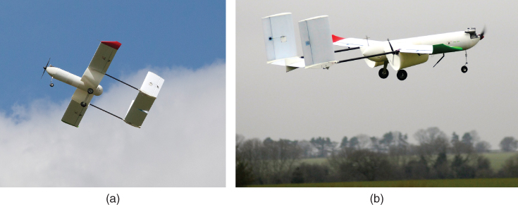
Figure 21.5 Aircraft with split all-moving elevator. (a) Without dividing fence. (b) With fence.
- Engine vibrations caused an autopilot to fail. We now extensively test the mountings of our autopilots in the lab prior to operations, using signals measured on the target aircraft, see Figure 21.6.
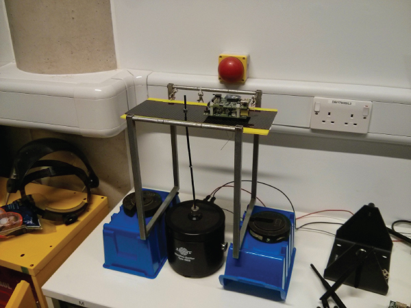
Figure 21.6 Autopilot on vibration test.
- Engine vibrations caused a power isolation switch to momentarily open and thus initiated the engine ignition safety cut-out system, forcing the pilot to glide the unpowered aircraft back to the landing strip.
- A sizing error during concept design led to an aircraft being built with wings that were too small given the installed power; this was not revealed until its first catapult launch, Figure 21.7.
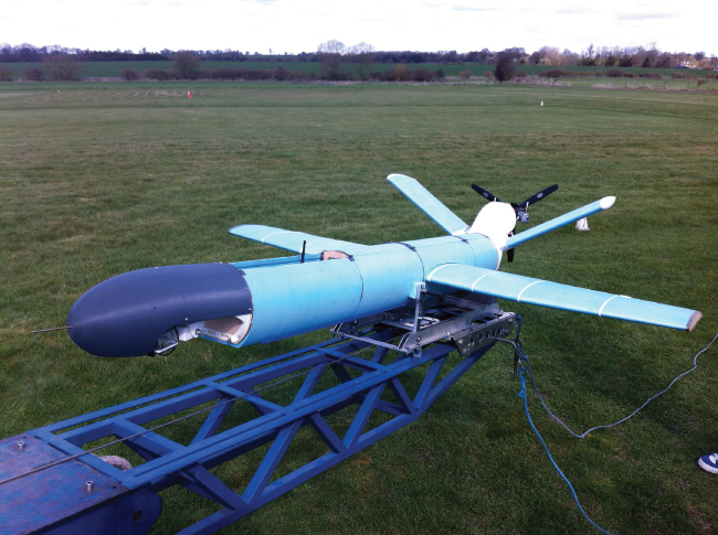
Figure 21.7 Student UAV with undersized wings. The open payload bay also added to stability issues.
- Repeated autonomous landings on a concrete runway led to low-cycle fatigue of a main wheel axle due to the significant impact loads experienced. Subsequent use of laser height finding mitigated these issues on automated landings, Figure 21.8.
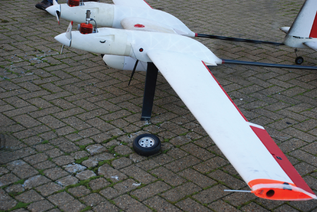
Figure 21.8 2SEAS aircraft after failure of main wheel axle.
Despite this apparent litany of failures, our aircraft fly successfully much more often than not; so we would encourage anyone setting out to design and build his/her own unmanned air system (UAS) to go right ahead. It is not nearly as daunting as one might initially think (even given the size of this book) and it can be a great deal of fun. Certainly, our student teams enjoy the experience enormously and clearly get a great thrill when “their” aircraft takes wing for the first time. Even those whose aircraft do not perform as desired learn a great deal from actually being directly involved in the whole process from first ideas to final flight.