Chapter i.2.3
Metals
Basic Principles
Introduction
Since large segments of the medical device industry rely on implants with one or more metallic parts – e.g., stents, heart valves, orthopedic hips and knees, plus oral/maxillofacial implants – metals have a highly significant place in the biomaterials market. In view of this wide utilization of metallic biomaterials, this chapter provides some basic principles underlying the quantification and design-related manipulation of composition, structure, and properties of metallic biomaterials. Major themes are the metallurgical principles underlying structure–property relationships, and the larger problem of design, production, and proper utilization of medical devices.
Steps in the Fabrication of Metallic Biomaterials
Understanding the structure and properties of metallic implant materials requires an appreciation of the metallurgical significance of the material’s processing history. Typically, any metallic medical device will differ in exactly how it is manufactured, so it is useful to look briefly at some generic processing steps in implant manufacture (Figure I.2.3.1A).
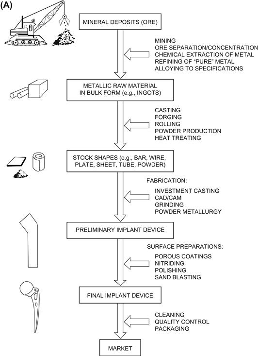
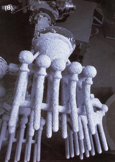
FIGURE I.2.3.1 (A) Generic processing history of a typical metallic implant device, in this case a hip implant.(B) Image of one step during the investment casting (“lost wax”) process of manufacturing hip stems; a rack of hip stems can be seen attached to a system of sprues through which molten metal can flow. At this point, ceramic investment material composes the mold into which the molten metal will flow and solidify during casting, thereby replicating the intended shape of a hip stem.
Metal-Containing Ore to Raw Metal Product
With the exception of noble metals such as gold (which do not represent a major fraction of implant metals), metals exist in the Earth’s crust in mineral form, wherein the metal is chemically combined with other elements, as in the case of metal oxides. These mineral deposits, or “ore,” must be located, mined, separated, and enriched for further processing into pure metal or various alloys. For example, in the case of titanium, certain mines in the southeastern United States yield sands containing common quartz along with mineral deposits of zircon, titanium, iron, and rare earth elements. The sandy mixture can be concentrated by using water flow and gravity to isolate titanium-containing compounds such as rutile (TiO2) and ilmenite (FeTiO3). To obtain rutile, which is particularly good for making metallic titanium, further processing typically involves electrostatic separations. Then, to extract titanium metal from the rutile, one method involves treating the ore with chlorine to make titanium tetrachloride liquid, which in turn is treated with magnesium or sodium to produce chlorides of the latter metals along with bulk titanium “sponge” according to the Kroll process. At this stage, the titanium sponge is not of controlled purity, so depending on the purity (“grade”) of the final titanium product that is sought, it is necessary to refine it further by using vacuum furnaces, remelting, and additional steps. All of this is critical in producing titanium with the appropriate properties, as exemplified in the production of the most common grades of commercially pure (CP) titanium; these grades differ in oxygen content by only tenths of a percent, yet these small differences in oxygen content make major differences in mechanical properties, including yield, tensile and fatigue strength of titanium.
After extraction steps, the resulting raw metal product eventually emerges in some type of bulk form, such as ingots, which can be supplied to raw materials’ vendors or metal manufacturers. For instance, in the case of multicomponent metallic implant alloys (i.e., made up of more than one element), the raw metal product will usually have to be further processed both chemically and physically. Processing steps can include remelting, addition of specific alloying elements, and controlled solidification from the melt, in order to produce an alloy that meets certain chemical and metallurgical specifications. For example, to make ASTM (American Society for Testing and Materials) F138 316L stainless steel, iron is alloyed with specific amounts of carbon, silicon, nickel, and chromium; and to make ASTM F75 or F90 alloy, cobalt is alloyed with specific amounts of chromium, molybdenum, carbon, nickel, and other elements. Table I.2.3.1 lists ASTM designations and typical properties of common metallic alloys for surgical implants.
TABLE I.2.3.1 Typical Mechanical Properties of Implant Metalsa
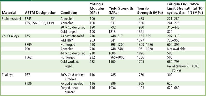
aData collected from references noted at the end of this chapter, especially Table 1 in Davidson and Georgette (1986).
bP/M HIP: Powder metallurgy product, hot-isostatically pressed.
Raw Metal Product to Stock Metal Shapes
A metal supplier will typically further process the bulk raw metal product (metal or alloy) into stock bulk shapes, such as bars, wire, sheet, rods, plates, tubes or powders. These stock shapes may then be sold to implant manufacturers, who typically want a stock shape that is closer to the final implant shape, e.g., a maker of screw-shaped dental implants would often buy rod stock of the appropriate metal as feedstock for screw-manufacturing machines.
A metal supplier might transform the raw metal product into stock shapes by a variety of processes, including remelting and continuous casting, hot rolling, forging, cold drawing through dies, etc. Depending on the metal there might also be heat-treating steps (i.e., carefully controlled heating and cooling cycles) designed to: facilitate further working or shaping of the stock; relieve the effects of prior plastic deformation (e.g., as in annealing) or produce a specific microstructure and properties in the stock material. Because of the high chemical reactivity of some metals at elevated temperatures, high temperature processing may require vacuum conditions or inert atmospheres to prevent unwanted uptake of oxygen by the metal, all of which can add to the cost of production. For instance, in the production of fine powders of ASTM F75 Co-Cr-Mo alloy, molten metal is ejected through a small nozzle to produce a fine spray of atomized metal droplets that solidify while cooling in an inert argon atmosphere.
Typically, stock shapes are chemically and metallurgically tested at this early stage to ensure that the chemical composition and microstructure of the metal sold to an implant company conforms to industry standards for surgical implants (e.g., ASTM Standards), as discussed later in this chapter. It makes sense that an implant manufacturer will demand quality assurance that they are buying an appropriate grade of metal from the supplier of the raw metal stock.
Stock Metal Shapes to Preliminary and Final Metal Devices
Typically, an implant manufacturer will buy stock material and then fabricate preliminary and final forms of the device. Specific steps depend on a number of factors, including the final geometry of the implant, the forming and machining properties of the metal, and the costs of alternative fabrication methods. Typical fabrication methods include investment casting (the “lost wax” process), conventional and computer-based machining (CAD/CAM), forging, powder metallurgical processes (e.g., hot isostatic pressing or HIP), and a range of grinding and polishing steps. A variety of fabrication methods are required because not all implant alloys can be feasibly or economically fabricated into a final form in the same way. As one example, cobalt-based alloys are extremely difficult to machine into the complicated shapes of some implants by conventional machining methods. Therefore, many cobalt-based alloys are frequently shaped into implant forms by investment casting (e.g., Figure I.2.3.1B) or by powder metallurgy. On the other hand, titanium is relatively difficult to cast, and is therefore often machined.
Other aspects of fabrication (which to some degree more accurately fall under the heading of surface treatment) involve the application of macro-, micro-, and/or nano-level coatings on implants, often with the intent of producing certain ranges of surface roughness. Such surface modifications have become more popular in recent years as a means to improve fixation of implants in bone or to improve interfacial bone growth. The surface coating or roughening can take various forms, and can require different fabrication technologies. In some cases, modifications to the surface have the potential to negatively affect the metallurgical properties of the underlying bulk implant metal. For example, in the case of alloy beads or “fiber metal” coatings for macro-porous implants, the manufacturer may employ high temperature sintering to apply the coating over specific regions of the implant surface (e.g., on the proximal portion of a femoral hip stem). Sintering involves heating the coating and substrate to about half (or more) of the alloy’s melting temperature in order to encourage diffusion, which in turn helps form the necks that join the beads to one another and to the implant’s surface. Such reasonably high temperatures can modify the underlying metallic substrate by allowing grain growth or other mechanisms, which could negatively affect the properties. An alternative to sintering is plasma or flame spraying a metal onto an implant’s surface. In this process, hot, high velocity gas plasma is charged with a metallic powder and directed at appropriate regions of an implant surface. The powder particles fully or partially melt, and then fall onto the substrate surface, where they solidify rapidly to form a tough coating. This has the advantage of not excessively heating the substrate.
Still more surface treatments are available, including ion implantation (to produce better surface properties), nitriding, and coating with a thin diamond film. For example, in nitriding, a high energy beam of nitrogen ions is directed at the implant under vacuum so that nitrogen atoms penetrate the surface and come to rest at sites in the substrate. Depending on the alloy, this process can produce enhanced properties, such as improved surface hardness and wear properties. (Many examples of different levels of surface modifications – ranging from the nano-level on up to the macro level – can be seen by perusing the advertisements for oral and maxillofacial implants in any one of the many journals devoted to such implants.)
Finally, a manufacturer of a metallic implant device will normally perform a set of finishing steps. These vary with the metal and manufacturer, but typically include chemical cleaning and passivation (i.e., rendering the metal inactive if exposed to a corrosive environment). Electrolytically-controlled treatments may also be used to remove machining chips or impurities that may have become embedded in the implant’s surface. As a rule, these steps are conducted according to good manufacturing practice (GMP), and ASTM specifications for cleaning and finishing implants. Notably, these finishing steps can be extremely important to the overall biological performance of the implant because they can affect the detailed surface properties of the medical device – which govern the surface of the device that comes in direct contact with the blood and other tissues at the implant site.
Microstructures and Properties of Implant Metals
In order to understand the properties of each alloy system in terms of microstructure and processing history, it is essential to know: (1) the chemical and crystallographic identities of the phases present in the microstructure; (2) the relative amounts, distribution, and orientation of these phases; and (3) the effects of the phases on properties. This section of the chapter emphasizes mechanical properties of metals used in implant devices, even though other properties, such as surface properties and wear properties, must also be considered and may in some instances be more critical to control. (Surface properties of materials are reviewed in more depth in Chapter I.1.5 of this textbook.) The basic principles are illustrated here in the context as applied to the stainless steels, cobalt-based alloys, and titanium-based alloys – which are very commonly used in medical devices. (More detailed discussions follow in the separate chapters in this textbook on stainless steel (Chapter I.2.3.B) and titanium (Chapter I.2.3.A).)
Microstructure and Mechanical Properties
There are many ways to manipulate microstructures and properties of metallic biomaterials. The following sections highlight just a few of the more commonly-encountered principles that apply to the most common metallic biomaterials, including the stainless steels, Co-Based alloys, and Ti-based alloys.
316L Stainless Steel
In this alloy, two common strengthening methods are cold-working and controlling grain size. The basis of each method is the idea of increasing the difficulty of slip of dislocations. In cold-working, the idea is to introduce more and more plastic deformation such that additional plastic flow becomes even more difficult. In decreasing grain size, the idea is to have more grain boundaries to interfere with the flow of dislocations on slip systems within each grain.
With 316L stainless (ASTM F138), typically it is used in a 30% cold-worked state, because this cold-worked metal has a markedly increased yield, ultimate tensile, and fatigue strength relative to the annealed state (Table I.2.3.1). The trade-off in this case is decreased ductility of the cold-worked metal, but ordinarily this is not a major concern in implant products. In dealing with grain size in 316L, the recommended grain size is ASTM #6 or finer, in which the grain size number n is defined in the formula N = 2n−1 , where N is the number of grains counted in a 1 in2 area at 100 × magnification (0.0645 mm2 actual area). As an example, when n = 6, the grain size is about 100 micrometers. The emphasis on a fine grain size is explained by the well-known Hall–Petch-type relationship (Hall, 1951; Petch, 1953), which relates mechanical yield stress and grain diameter as follows:
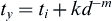
where ty and ti are the yield and friction stress, respectively; d is the grain diameter; k is a constant associated with propagation of deformation across grain boundaries; and m is approximately 0.5. This equation indicates that a higher yield stress may be achieved by a metal with a smaller grain diameter d, all other things being equal. A key determinant of grain size is manufacturing history, including details on solidification conditions, cold-working, annealing cycles, and recrystallization.
Cobalt-Based Alloys
Cobalt-based alloys include Haynes-Stellite 21 and 25 (ASTM F75 and F90, respectively), forged Co-Cr-Mo alloy (ASTM F799), and multiphase (MP) alloy MP35N (ASTM F562). The F75 and F799 alloys are virtually identical in composition, each being about 58–70% Co and 26–30% Cr, with the key difference in their processing history. The other two alloys, F90 and F562, have slightly less Co and Cr, but more Ni (F562) or more tungsten (F90).
To consider the example of F75 alloy (which has a long history in both the aerospace and biomedical implant industries), the main attribute of this alloy is corrosion resistance in chloride environments, which is related to its bulk composition and surface oxide (nominally Cr2O3). When F75 is cast into shape by investment casting (e.g., the “lost wax” process; Figure I.2.3.1B), the alloy is first melted at 1350–1450°C and then poured or pressurized into ceramic molds of the desired shape (e.g., femoral stems for artificial hips, oral implants, dental partial bridgework). The sometimes intricately-shaped molds are made by fabricating a wax pattern to near-final dimensions of the implant and then coating (or “investing”) the pattern with a special ceramic, which then holds its shape after the wax is burned out prior to casting – hence the name “lost wax” for the process. Molten metal is poured into the ceramic mold through sprues, or pathways, and then, once the metal has solidified into the shape of the mold, the ceramic mold is cracked away and processing of the metal continues toward the final device.
Depending on the exact details of the casting process, at least three microstructural features can come into play as strong determinants of implant properties. First, as-cast F75 alloy typically consists of a Co-rich matrix (alpha phase) plus interdendritic and grain boundary carbides (primarily M23C6, where M represents Co, Cr or Mo). Overall, the relative amounts of the alpha and carbide phases should be approximately 85% and 15%, respectively, but due to non-equilibrium cooling, it is possible that a “cored” microstructure may develop. In this situation, the interdendritic regions become rich in solute (Cr, Mo, C) and contain carbides, while the dendrites become depleted in Cr and richer in Co. This creates an unfavorable electrochemical situation, with the Cr-depleted regions being anodic with respect to the rest of the microstructure. (This is also an unfavorable situation if a porous coating will subsequently be applied by sintering to this bulk metal.) Subsequent solution-annealing heat treatments at 1225°C for 1 hour can help alleviate this situation.
A second issue with F75 solidification is that dendrites will form, along with a relatively large grain size. This is generally undesirable because it decreases the yield strength via a Hall–Petch relationship between yield strength and grain diameter (recall the discussion from the section on stainless steel above). An example of dendritic growth and large grain diameter (approximately 4 mm) can be easily seen in Figures I.2.3.2A and I.2.3.2B, which show metallographic cross-sectional views through a femoral hip stem, and also a dental implant (Figures I.2.3.2C, I.2.3.2D) manufactured by investment casting.
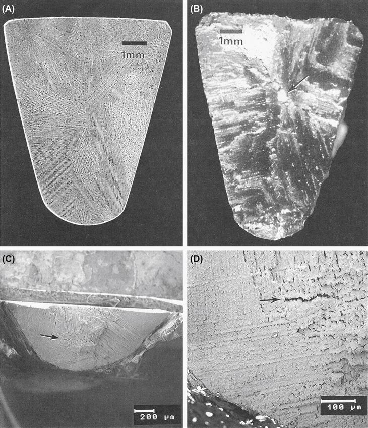
FIGURE I.2.3.2 (A) Macrophoto of a metallographically polished and etched cross-section of a cast Co–Cr–Mo ASTM F75 femoral hip stem, showing dendritic structure and large grain size. (B) Macrophoto of the fracture surface of the same Co–Cr–Mo ASTM F75 hip stem as in (A). Arrow indicates large inclusion within the central region of the cross section. Fracture of this hip stem occurred in vivo. (C), (D) Scanning electron micrographs of the fracture surface from a cast F75 subperiosteal dental implant. Note the large grain size, dendritic microstructure, and interdendritic microporosity (arrows).
A third issue with cast F75 is that casting defects may arise, e.g., Figure I.2.3.2B shows an inclusion in the middle of the cross-section through the distal third of the femoral hip stem. The inclusion was a particle of the ceramic mold (investment) material, which presumably broke off and became trapped within the interior of the mold while the metal was solidifying. This contributed to a fatigue fracture of the implant device in vivo, most likely because of stress concentrations and crack initiation sites associated with the ceramic inclusion. For similar reasons, it is also desirable to avoid macro- and microporosity arising from metal shrinkage upon solidification of castings. As an example of such porosity, Figures I.2.3.2C and I.2.3.2D exemplify a markedly dendritic microstructure with large grain size and microporosity at the fracture surface of a dental implant fabricated by investment casting.
To avoid problems such as the ones described above with cast F75, powder metallurgical techniques have been designed and used by some implant manufacturers. For example, in hot isostatic pressing (HIP), a fine powder of F75 alloy is compacted and sintered together under appropriate pressure and temperature conditions (about 100 MPa at 1100°C for 1 hour) and then forged to final shape. The typical microstructure shows a much smaller grain size than with casting (e.g., about 8 microns), which has the benefit of a much higher yield strength (via the Hall–Petch relationship), and better ultimate and fatigue properties than the as-cast alloy (Table I.2.3.1).
One final example with F75 alloy is the issue of porous-coated implants made by sintering. Here the idea is to sinter (join) the beads together, and to the underlying bulk substrate. With Co-based alloys like F75, however, sintering can be difficult, requiring temperatures near the melting point (1225°C), which in turn can decrease the fatigue strength of the substrate alloy. For example, cast/solution-treated F75 alloy has a fatigue strength of about 200–250 MPa, but this strength can decrease to about 150 MPa after porous coating treatments – evidently from further phase changes in the non-equilibrium cored microstructure in the original cast F75 alloy. On the other hand, it has been found that a modified sintering treatment can return the fatigue strength back up to about 200 MPa (Table I.2.3.1).
Titanium-Based Alloys
Commercially pure (CP) titanium (ASTM F67) and extra-low interstitial (ELI) Ti-6AI-4V alloy (ASTM F136) are the two most common titanium-based implant biomaterials (although within the category of CP Ti there are four grades). F67 CP Ti is 98.9–99.6% Ti. The oxygen content of CP Ti, as well as the content of other interstitial elements (e.g., C and N), affect its yield, tensile, and fatigue strengths significantly. With Ti-6AI-4V ELI alloy, the individual Ti-AI and Ti-V phase diagrams suggest the effects of the alloying additions in the ternary alloy; since Al is an alpha (HCP) phase stabilizer and V is a beta (BCC) phase stabilizer, Ti-6AI-4V alloy used for implants is an alpha-beta alloy.
For CP titanium implants (as exemplified by many current dental implants) typical microstructures are made up of single-phase alpha titanium (having the HCP structure), in which there is typically mild (30%) cold-work and grain diameters in the range of 10–150 microns, depending on manufacturing. The nominal mechanical properties are listed in Table I.2.3.1. Beyond cold-work, interstitial elements (O, C, N) in both CP titanium and the Ti-6AI-4V alloy strengthen the metal through interstitial solid solution strengthening mechanisms, with nitrogen having approximately twice the hardening effect (per atom) of either carbon or oxygen. As noted earlier, the oxygen content of CP Ti (and the interstitial content generally) affects its yield, tensile, and fatigue strengths significantly. For example, data available in the ASTM standard show that at 0.18% oxygen (grade 1), the yield strength is about 170 MPa, whereas at 0.40% (grade 4) the yield strength is about 485 MPa.
Likewise, the ASTM standard shows that the tensile strength increases with oxygen content. The literature also reveals that the fatigue limit of unalloyed CP Ti is typically increased by interstitial content, in particular the oxygen content. For example, Figure I.2.3.3A shows data from Beevers and Robinson (1969), who tested vacuum-annealed CP Ti having a grain size in the range 200–300 microns in tension-compression at a mean stress of zero, at 100 cycles/sec. The 107 cycle endurance limit, or fatigue limit, for Ti 115 (0.085 wt% O, grade 1), Ti 130 (0.125 wt% O, grade 1), and Ti 160 (0.27 wt% O, grade 3) was 88.3, 142, and 216 MPa, respectively. Figure I.2.3.3B shows similar results from Turner and Roberts’ (1968a) fatigue study on CP Ti (tension-compression, 160 cycles/sec, mean stress equals zero) having a grain size in the range 26–32 micrometers. Here the fatigue limit for “HP Ti” (0.072 wt% O, grade 1), Ti 120 (0.087 wt% O, grade 1), and Ti 160 (0.32 wt% O, grade 3) was 142, 172, and 295 MPa, respectively – again showing an increasing endurance limit with increasing oxygen content. Also, for grade 4 Ti in the cold-worked state, Steinemann et al. (1993) reported a 107 endurance limit of 430 MPa. Other workers (Conrad et al., 1973) have reported fatigue studies on CP Ti at 300°K, and noted that the ratio of fatigue limit to yield stress is relatively constant at about 0.65, independent of interstitial content and grain size (Figure I.2.3.3C). The work of Turner and Roberts also reported that the ratio f (defined as fatigue limit/ultimate tensile strength) – also referred to as the “fatigue ratio” in materials design textbooks (e.g., see Charles and Crane, 1989, p. 106) – was 0.43 for the high-purity Ti (0.072 wt% O), 0.5 for Ti 120 (0,087 wt% O), and 0.53 for Ti 160 (0.32 wt% O). It seems clear that interstitial content affects the yield and tensile and fatigue strengths in CP Ti.
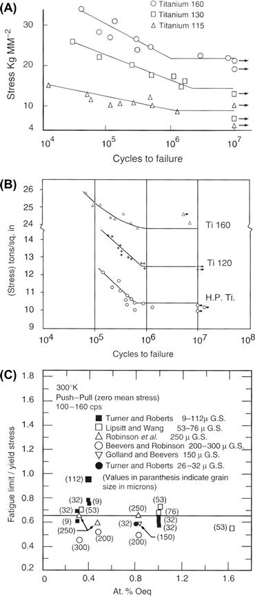
FIGURE I.2.3.3 (A) S–N curves (stress amplitude–number of cycles to failure) at room temperature for CP Ti with varying oxygen content (see text for O content of Ti 160, 130, and 115), from Beevers and Robinson (1969). (B) S–N curves at room temperature for CP Ti with varying oxygen content (see text), from Turner and Roberts (1968a). (C) Ratio of fatigue limit to yield stress in unalloyed Ti at 300°K as a function of at% oxygen and grain size, from Conrad et al. (1973). See Bibliography for details of references given within this figure.
At the same time, cold-work appears to increase the fatigue properties of CP Ti. For example, Disegi (1990) quoted bending fatigue data for annealed versus cold-worked CP Ti in the form of un-notched 1.0 mm thick sheet, and showed a moderate increase in ultimate tensile strength (UTS) and “plane bending fatigue strength,” when comparing annealed versus cold-rolled Ti samples. Based on these data, the ratio of fatigue strength to ultimate tensile strength (“endurance ratio” or “fatigue ratio,” see paragraph above) varied between 0.45 and 0.66. On the other hand, the ASM Handbook Fatigue and Fracture (Wagner et al., 1996) noted that the fatigue limit for high purity Ti only increased about 10% relative to the annealed material, while Disegi’s data showed that the fatigue strength increased by about 28%, on average, with cold-work.
Concluding Remarks
Metallurgical structure–property relationships inform materials selection in medical implant design, just as they do in the design of any well-engineered product. Although this chapter’s emphasis has been on mechanical properties (for the sake of specificity), other properties – including surface properties – are receiving increasing attention in relation to biological performance of implants. Examples of this latter theme are efforts to attach relevant biomolecules to metallic implant surfaces to promote certain desired interfacial activities, and attempts to develop special surface textures on implants to guide molecular and cellular reactions; these subjects can be researched further based on the following Bibliography.
Another point to remember is that the intrinsic material properties of metallic implants – e.g., Young’s elastic modulus, yield strength, or fatigue strength – are not the sole determinant of implant performance and success; overall implant design is also critical. So while it is certainly true that inadequate attention to intrinsic material properties can doom a device to failure, it is also true that even with the best intrinsic properties, a device may still fail because of faulty structural properties, inappropriate use of the implant, surgical error or overall inadequate mechanical design of the implant. As an illustration of this latter point, Figure I.2.3.4 shows a plastically-deformed 316L stainless steel Harrington spinal distraction rod (circa 1980s) that failed in vivo because of metallurgical fatigue. A failure analysis of this case concluded that failure did not occur because of any shortcomings in the rod’s 316L cold-worked stainless steel; rather, the fracture occurred because of a combination of other factors, namely: (1) the surgeon plastically bent the rod to make it fit a bit better in the patient’s back (and the rod company sold rod-bending jigs!), but the bend in the rod increased the bending moment and bending stresses on the rod at the first ratchet junction, which was a known problem area in terms of fractures in vivo; (2) the stress concentrations at the fracture site at the ratchet end of the rod were severe enough to significantly increase the tensile stresses at the first ratchet junction, which was the eventual site of the fatigue fracture; and (3) spinal fusion did not occur in the patient, which contributed to relatively persistent loading of the rod over several months post-implantation, thus further predisposing the implant to fatigue fracture. Here the point is that all three of these factors could have been anticipated and considered in the original design of the rod, during which both structural and material properties could have been considered in various stress analyses to forestall fatigue failure. While this example comes from spinal implants, there are many similar examples with the same theme in the orthopedic, oral, and maxillofacial areas. The take-home message here is that implant design is generally a multifaceted problem in which biomaterials selection is only a part of the overall design problem.
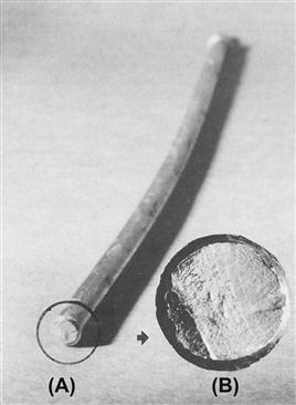
FIGURE I.2.3.4 The smooth part of a 316L stainless steel Harrington spinal distraction rod that fractured by fatigue in vivo. Note the bend in the rod (the rod was originally straight) and (insert) the relationship of the crack initiation zone of the fracture surface to the bend. The inserted photo shows the nature of the fatigue fracture surface, which is characterized by a region of “beach marks” and a region of sudden overload failure.
(Photo courtesy of Brunski, J. B., Hill, D. C. & Moskowitz, A. (1983). Stresses in a Harrington distraction rod: Their origin and relationship to fatigue fractures in vivo. J. Biomech. Eng., 105, 101–107.)
Bibliography
1. American Society for Testing and Materials. ASTM Standards for Medical and Surgical Materials and Devices, Authorized Reprint from Annual Book of ASTM Standards. Philadelphia, PA: ASTM; 1978.
2. Beevers CJ, Robinson J. Some observations on the influence of oxygen content on the fatigue behavior of alpha-titanium. J Less-Common Metals. 1969;17:345–352.
3. Brunski JB, Hill DC, Moskowitz A. Stresses in a Harrington distraction rod: Their origin and relationship to fatigue fractures. in vivo J Biomech Eng. 1983;105:101–107.
4. Charles JA, Crane FA. Selection and Use of Engineering Materials. 2nd ed. Halley Court, Oxford, UK: Butterworth-Heinemann Ltd; 1989.
5. Compte P. Metallurgical observations of biomaterials. In: Boretos JW, Eden M, eds. Contemporary Biomaterials. Park Ridge, NJ: Noyes Publishers; 1984:66–91.
6. Conrad H, Doner M, de Meester B. Critical review: Deformation and fracture. In: Jaffee RI, Burte HM, eds. New York, NY: Plenum Press; 1973:969–1005. Titanium Science and Technology. Vol. 2.
7. Davidson JA, Georgette FS. State-of-the-art materials for orthopaedic prosthetic devices. In: Implant Manufacturing and Material Technology. Itasca, IL: Proc. Soc of Manufacturing Engineering; 1986.
8. Disegi, J. (1990). AO/ASIF Unalloyed Titanium Implant Material. Technical brochure available from Synthes (USA), PO Box 1766, 1690 Russell Road, Paoli, PA, 19301.
9. Golland DI, Beevers CJ. Some effects of prior deformation and annealing on the fatigue response of alpha titanium. J Less-Common Metals. 1971a;23:174.
10. Golland DI, Beevers CJ. The effect of temperature on the fatigue response of alpha-titanium. Met Sci J. 1971b;5:174.
11. Gomez M, Mancha H, Salinas A, Rodriguez JL, Escobedo J, et al. Relationship between microstructure and ductility of investment cast ASTM F-75 implant alloy. J Biomed Mater Res. 1997;34:157–163.
12. Hall EO. The deformation and ageing of mild steel: Discussion of results. Proc Phys Soc., (London). 1951;64B:747–753.
13. Hamman G, Bardos DI. Metallographic quality control of orthopaedic implants. In: McCall JL, French PM, eds. Metallography as a Quality Control Tool. New York, NY: Plenum Publishers; 1980;221–245.
14. Honeycombe RWK. The Plastic Deformation of Metals. New York, NY: St. Martin’s Press; 1968; 234.
15. Kasemo B, Lausmaa J. Biomaterials from a surface science perspective. In: Ratner BD, ed. Surface Characterization of Biomaterials. New York: Elsevier; 1988;1–12. Chapter 1.
16. Lipsitt HA, Wang DY. The effects of interstitial solute atoms on the fatigue limit behavior of titanium. Trans AIME. 1961;221:918.
17. Nanci A, Wuest JD, Peru L, Brunet P, Sharma V, et al. Chemical modification of titanium surfaces for covalent attachment of biological molecules. J Biamed Mater Res. 1998;40:324–335.
18. Petch NJ. The cleavage strength of polycrystals. J Iron Steel Inst., (London). 1953;173:25.
19. Pilliar RM, Weatherly GC. Developments in implant alloys. CRC Crit Rev Biocompatibility. 1984;1(4):371–403.
20. Richards Medical Company. Medical Metals. Memphis, TN: Richards Medical Company Publication No 3922, Richards Medical Co; 1985; [Note: This company is now known as Smith & Nephew Richards, Inc.].
21. Robinson SL, Warren MR, Beevers CJ. The influence of internal defects on the fatigue behavior of alpha-titanium. J Less-Common Metals. 1969;19:73–82.
22. Steinemann SG, Mansli P-A, Szmuckler-Moncler S, Semlitsch M, Pohler O, et al. Beta-titanium alloy for surgical implants. In: Froes FH, Caplan I, eds. Titanium 92 Science and Technology. Warrendale, PA: The Minerals, Metals & Materials Society; 1993;2689–2698.
23. Turner NG, Roberts WT. Fatigue behavior of titanium. Trans Met Soc AIME. 1968a;242:1223–1230.
24. Turner NG, Roberts WT. Dynamic strain ageing in titanium. J Less-Common Metals. 1968b;16:37.
25. Wagner L, et al. Fatigue life behavior. In: Lampman S, Davidson GM, Reidenbach F, Boring RL, Hammel A, eds. Metals Park, Ohio: ASM International; 1996;837–853. ASM Handbook Fatigue and Fracture. Vol. 19.
26. Zimmer USA. Fatigue and Porous Coated Implants. Warsaw, IN: Zimmer Technical Monograph, Zimmer USA; 1984a.
27. Zimmer USA. Metal Forming Techniques in Orthopaedics. Warsaw, IN: Zimmer Technical Monograph, Zimmer USA; 1984b.
28. Zimmer USA. Physical and Mechanical Properties of Orthopaedic Alloys. Warsaw, IN: Zimmer Technical Monograph, Zimmer USA; 1984c.
29. Zimmer USA. Physical Metallurgy of Titanium Alloy. Warsaw, IN: Zimmer Technical Monograph, Zimmer USA; 1984d.