Each GPIO pin is only able to handle a certain current before it burns out (a maximum of 16 mA from a single pin or 30 mA in total), and similarly, the RGB LED should be limited to no more than 100 mA. By adding a resistor before or after an LED, we will be able to limit the current that will be passed through it and control how bright it is (more current will equal a brighter LED).
Since we may wish to power more than one LED at a time, we typically aim to set the current as low as we can get away with while still providing enough power to light up the LED.
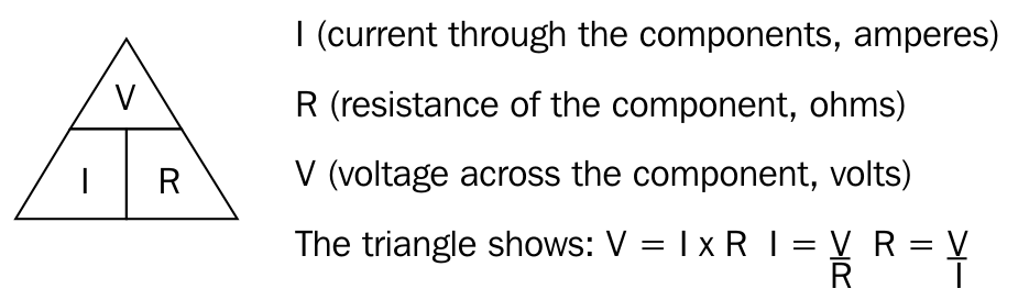
We can use Ohm's law to tell us how much resistance to use to provide a particular current. The law is as shown in the following diagram:
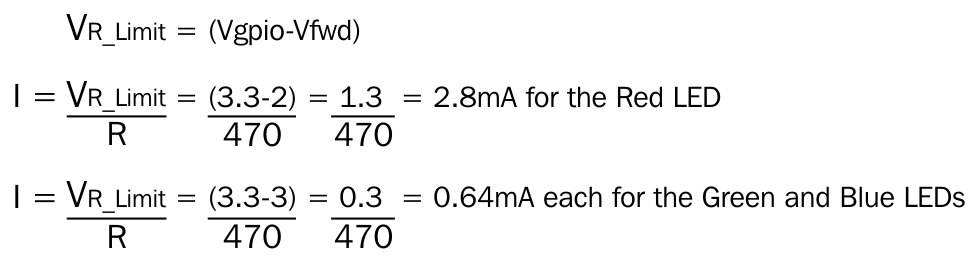
We will aim for a minimum current (3 mA) and maximum current (16 mA), while still producing a reasonably bright light from each of the LEDs. To get a balanced output for the RGB LEDs, I tested different resistors until they provided a near white light (when viewed through a card). A 470 ohm resistor was selected for each one (your LEDs may differ slightly):

The voltage across the resistor is equal to the GPIO voltage (Vgpio = 3.3V) minus the voltage drop on the particular LED (Vfwd); we can then use this resistance to calculate the current used by each of the LEDs, as shown in the following formulas: