As you would have understood by now, we can control any AC electrical appliances as per our needs. We have understood switching and have also perfected the way we can vary the intensity of light and the speed of fans. But did you notice one thing? Sooner or later as our system gets more and more complex, the number of GPIOs needed will increase. There will come a moment when you will want to have more and more devices connected to your Raspberry Pi; however, you will not be able to do so due to lack of physical ports.
This is a very common situation in electronics. As always, there is a solution for this problem as well. This solution is known as a multiplexer. The basic job of a multiplexer is to multiply the number of ports in any computer system. Now you must be thinking, how is it able to do so?
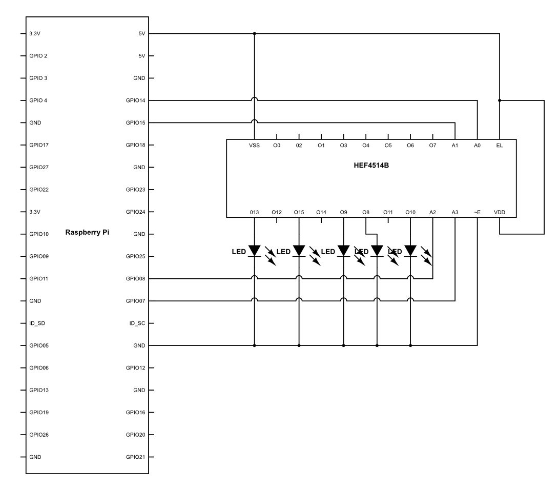
The concept is extremely simple. Let's first look at the diagram of a multiplexer here:

In the preceding diagram, you can see that there are two ends to the multiplexer—one being the signal output lines and the other opposite to it. The first thing we need to understand is that the multiplexer is a bidirectional device, that is, it sends the data from the multiplexer to the connected devices and also vice versa.
Now, firstly, we have the power line, which is pretty basic. It is there to power up the multiplexer itself. Then, we have Signal Lines, which have two ports, the Sig and EN. EN stands for enable, which means that until the time EN is not high, the data communication will not happen either way. Then we have something called Sig. This is the port that is connected to the GPIO of Raspberry Pi for data communication. Next we have the selection line. As you can see, we have four ports for it, namely, S0, S1, S2, and S3. The selection lines have a purpose of selecting a particular port that needs to be selected. The following is a table that will clarify what exactly is happening:
| S0 | S1 | S3 | S4 | Selected output |
| 0 | 0 | 0 | 0 | C0 |
| 1 | 0 | 0 | 0 | C1 |
| 0 | 1 | 0 | 0 | C2 |
| 1 | 1 | 0 | 0 | C3 |
| 0 | 0 | 1 | 0 | C4 |
| 1 | 0 | 1 | 0 | C5 |
| 0 | 1 | 1 | 0 | C6 |
| 1 | 1 | 1 | 0 | C7 |
|
0 |
0 | 0 | 1 |
C8 |
|
1 |
0 | 0 | 1 |
C9 |
|
0 |
1 | 0 | 1 |
C10 |
|
1 |
1 | 0 | 1 |
C11 |
| 0 | 0 | 1 | 1 |
C12 |
|
1 |
0 | 1 | 1 |
C13 |
| 0 | 1 | 1 | 1 |
C14 |
| 1 | 1 | 1 | 1 |
C15 |
In the preceding table, you can see that by using various logic combinations on the selection lines, various lines can be addressed. Let's say, for example, we have the following sequence on the selection pins—S0 = 1, S1 = 0, S2 = 1, S3 = 1. If this is the input on the selection pins from Raspberry Pi, then the pin number C13 will be selected. This basically means that now C13 can communicate the data to and from the pin Sig for the multiplexer. Also, we must remember that the enable pin must be high for the data transfer to happen.
In a similar fashion, we can go ahead and address all the 16 pins of the multiplexer. Hence, if we see it logically, then by using six pins of Raspberry Pi, we can go ahead and utilize 16 GPIOs. Now that we have understood the basics of multiplexing, let's go ahead and try using one of them.
Once the hardware is connected, let's go ahead and upload the following code:
import RPi.GPIO as GPIO
import time

GPIO.setmode(GPIO.BCM)
GPIO.setwarnings(False)

S0 = 21
S1 = 22
S2 = 23
S3 = 24

GPIO.setup(S0,GPIO.OUT)
GPIO.setup(S1,GPIO.OUT)
GPIO.setup(S2,GPIO.OUT)

While True:

    GPIO.output(S0,1)
    GPIO.output(S1,0)
    GPIO.output(S2,1)
    GPIO.output(S4,1)

    time.sleep(1)

    GPIO.output(S0,1)
    GPIO.output(S1,1)
    GPIO.output(S2,1)
    GPIO.output(S4,1)

    time.sleep(1)

    GPIO.output(S0,1)
    GPIO.output(S1,0)
    GPIO.output(S2,0)
    GPIO.output(S4,1)

    time.sleep(1)

    'GPIO.output(S0,0)
    GPIO.output(S1,0)
    GPIO.output(S2,0)
    GPIO.output(S4,1)

    time.sleep(1)

    GPIO.output(S0,0)
    GPIO.output(S1,1)
    GPIO.output(S2,0)
    GPIO.output(S4,1)

    time.sleep(1) }
Here, what we are essentially doing is, triggering the selection lines one by one to address every single port where the LED is connected. Whenever that happens, the LED corresponding to it glows. Also, the reason it glows is because the signal port Sig is connected to 3.3V of Raspberry Pi. Hence, send a logic high to whichever port it is connected to.
This is one of the basic ways in which the multiplexer works. This can be incredibly useful when we will be using multiple devices and sensors.