You will need the RGB LED module shown in the following picture:
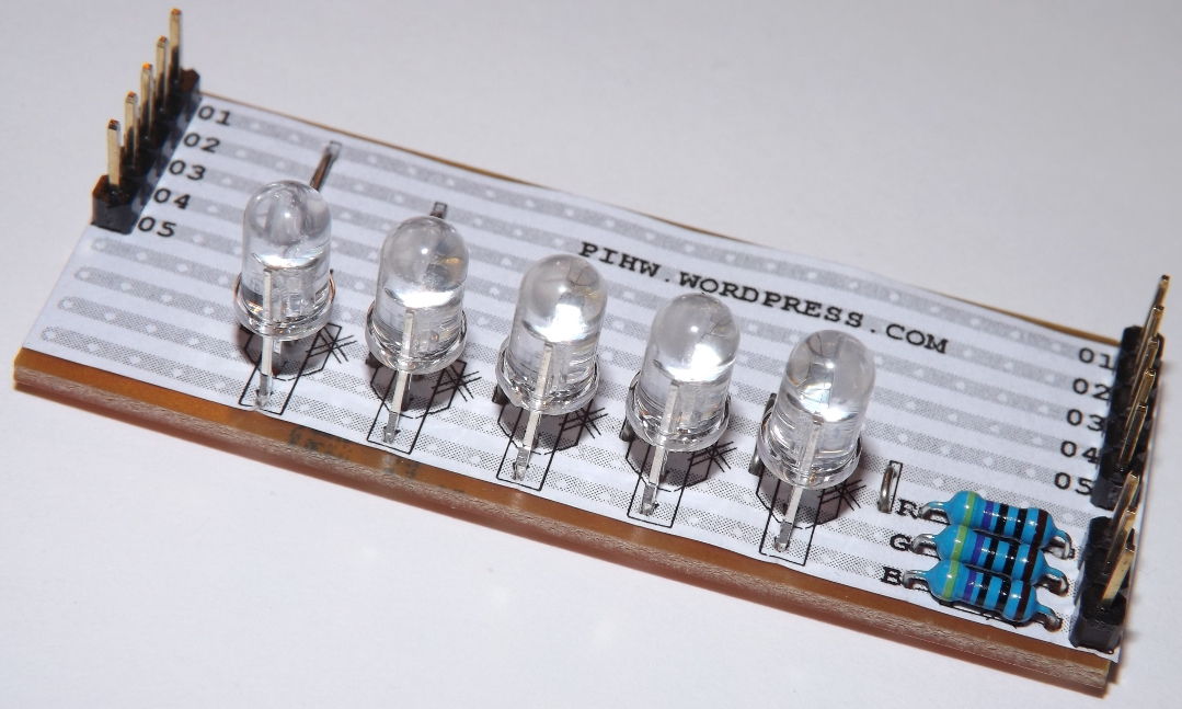
As you can see in the preceding photo, the RGB LED module from http://pihardware.com/ comes with GPIO pins and a DuPont female-to-female cable for connecting it. Although there are two sets of pins labelled from 1 to 5, only one side needs to be connected.
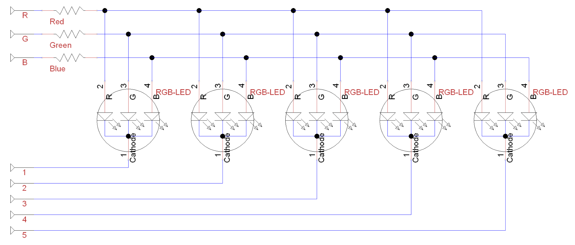
Alternatively, you can recreate your own with the following circuit using five common cathode RGB LEDs, 3 x 470 ohm resistors, and a Vero prototype board (or large breadboard). The circuit will look as shown in the following diagram:
You will need to connect the circuit to the Raspberry Pi GPIO header as follows:
|
RGB LED |
1 |
2 |
3 |
4 |
||||||||||||||||
|
Rpi GPIO pin |
2 |
4 |
6 |
8 |
10 |
12 |
14 |
16 |
18 |
20 |
22 |
24 |
26 |
28 |
30 |
32 |
34 |
36 |
38 |
40 |
|
Rpi GPIO pin |
1 |
3 |
5 |
7 |
9 |
11 |
13 |
15 |
17 |
19 |
21 |
23 |
25 |
27 |
29 |
31 |
33 |
35 |
37 |
39 |
|
RGB LED |
5 |
R |
G |
B |