The following photo depicts an infrared proximity sensor:
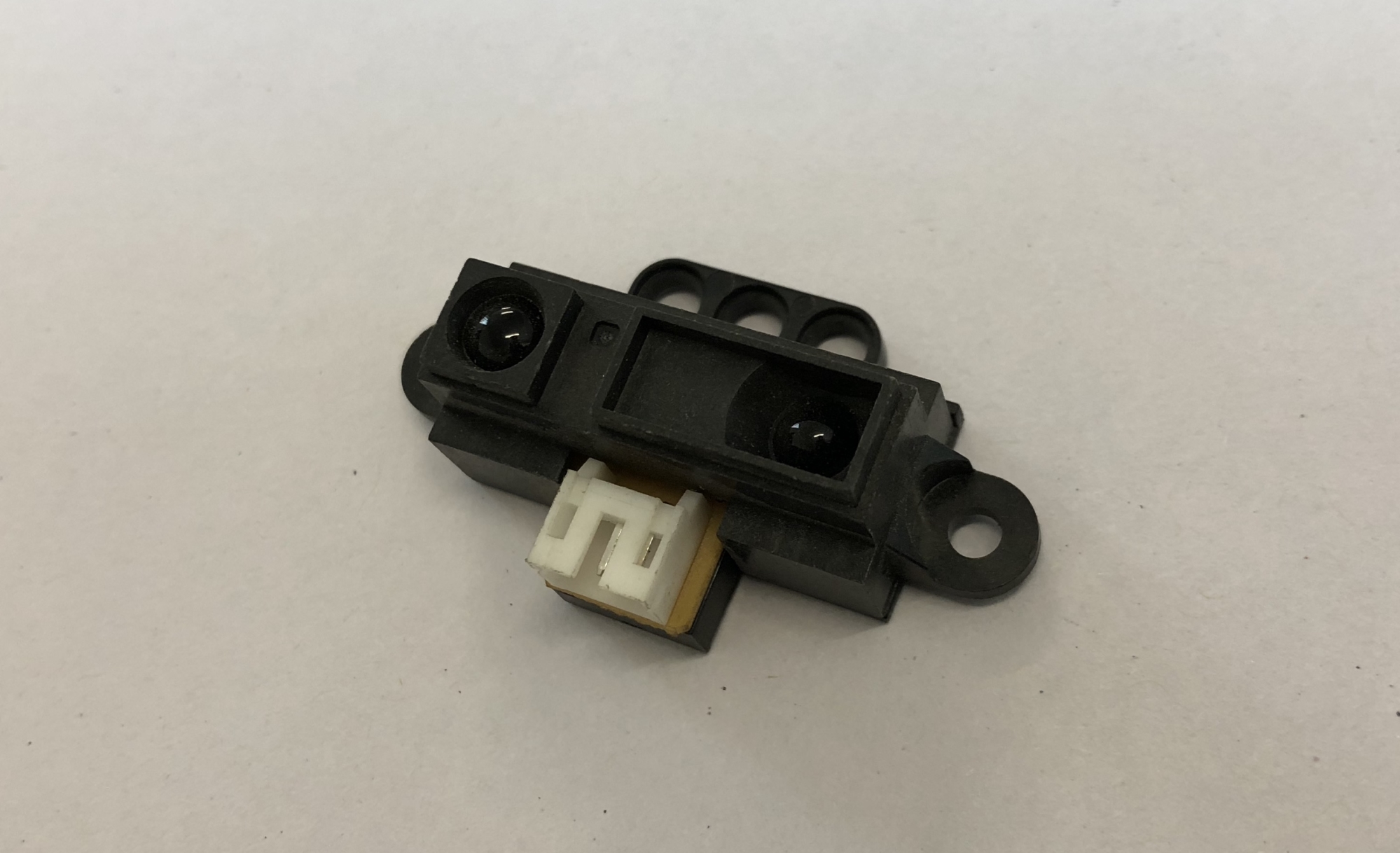
It consists of two major parts—the sensor and the transmitter. The transmitter emits IR waves; these Infrared (IR) waves then hit the object and come back to the sensor, as depicted in the following diagram..
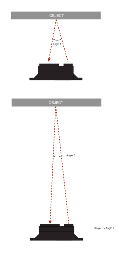
Now, as you can see in the preceding diagram, the emitted IR waves bounces back from a surface at a different distance from the sensor, then they makes an angular approach to the sensor. Now, because the distance between the transmitter and the sensor is fixed at all points of time, the angle corresponding to reflected IR waves would be proportional to the distance it has traveled before bouncing off. There are ultraprecise sensors in the IR proximity sensors that are capable of sensing the angle at which the IR waves approach it. By this angle, it gives the user a value of distance corresponding to it. This method of finding distance is named triangulation, and it has been used widely in the industry. One more thing we need to keep in mind is that we are all surrounded by IR radiation as we mentioned earlier in the chapters; any object above absolute zero temperature would have corresponding waves emitted to it. Also, the sunlight around us is having ample amount of IR radiations. Hence, these sensors have a built-in circuitry to compensate for it; however, there is only so much it can do. That's why, this solution might have some trouble when dealing with direct sunlight.
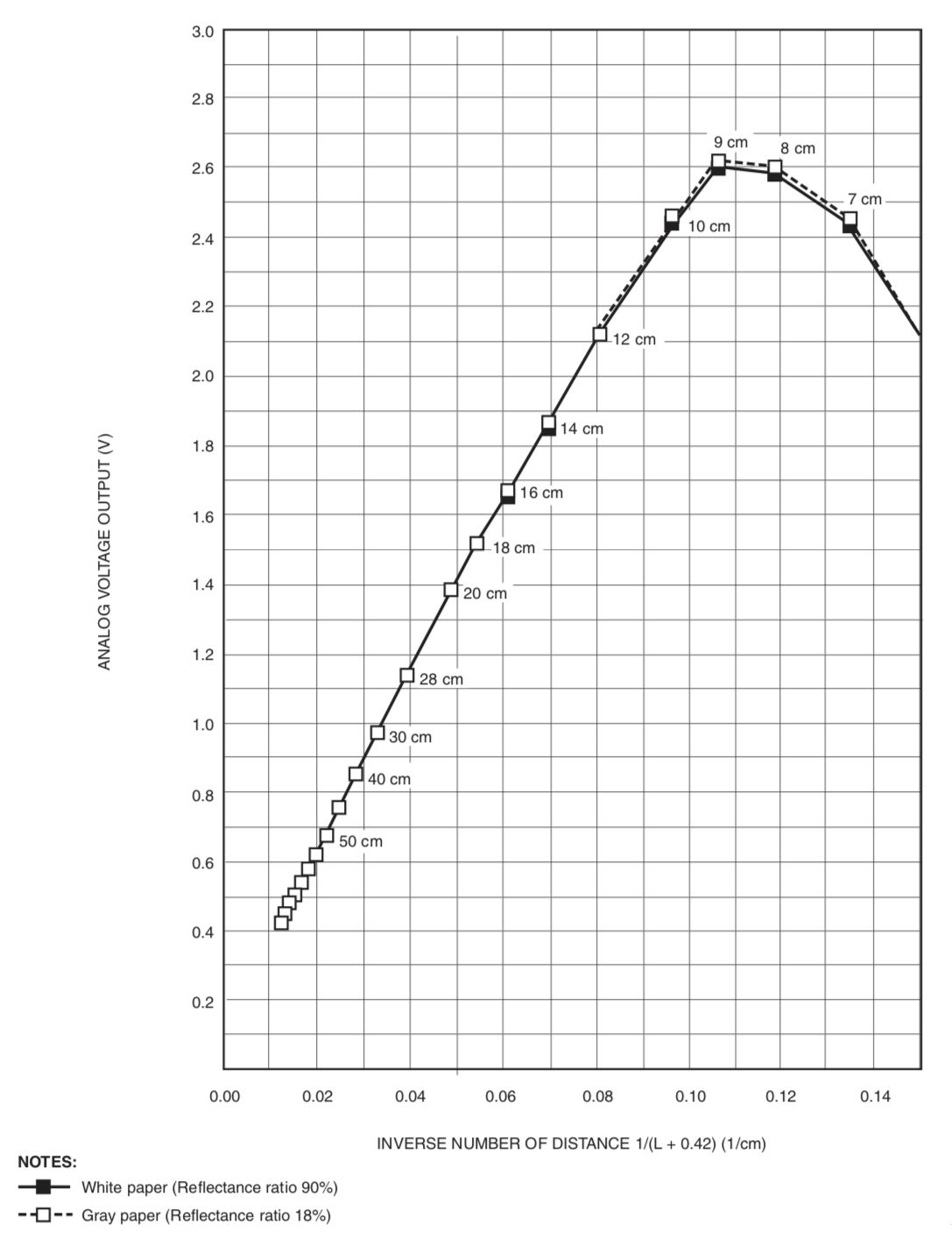
Now, enough of the theory, let's see how the car actually works. The IR proximity sensor we are using in this example is an analog sensor by Sharp with part code GP2D12. It has an effective sensing range of 1000-800 mm. The range is also dependent on the reflectivity of the surface of the object in question. The darker the object, the shorter the range. This sensor has three pins. As you might have guessed, there is one for VCC, another for ground, and the last for the signal. This is an analog sensor; hence, the distance reading would be given based on the voltage. Generally with most analog sensors you would get a graph which will depict the various voltages at various sensing ranges. The output is basically depending on the internal hardware of the sensor and its construction so it can be vastly different. Below is a graph for our sensor and its output :
Okay then, so far so good. As we know that Raspberry Pi does not accept analog input; hence, we will go ahead and use what we have used earlier as well, an ADC. We will be using the same ADC we have used before.