So, let me introduce you to servo motor. Servo motor is basically a motor with a few added components. Now to understand what those added components, let's first go through this example. Let's say that you want to go to London. Now to see how you have to go there and what would be the route to reach London, the first thing you need to know is that where exactly you are now. If you don't know where you are currently, it is impossible to calculate a route. Similarly, if we want to reach a certain position of motor, we need to know where the shaft of the motor is standing right now. To do this, we use a potentiometer. A potentiometer is basically a variable resistor that essentially has a shaft that when rotated changes the value of resistance. A variable resistor looks like this:
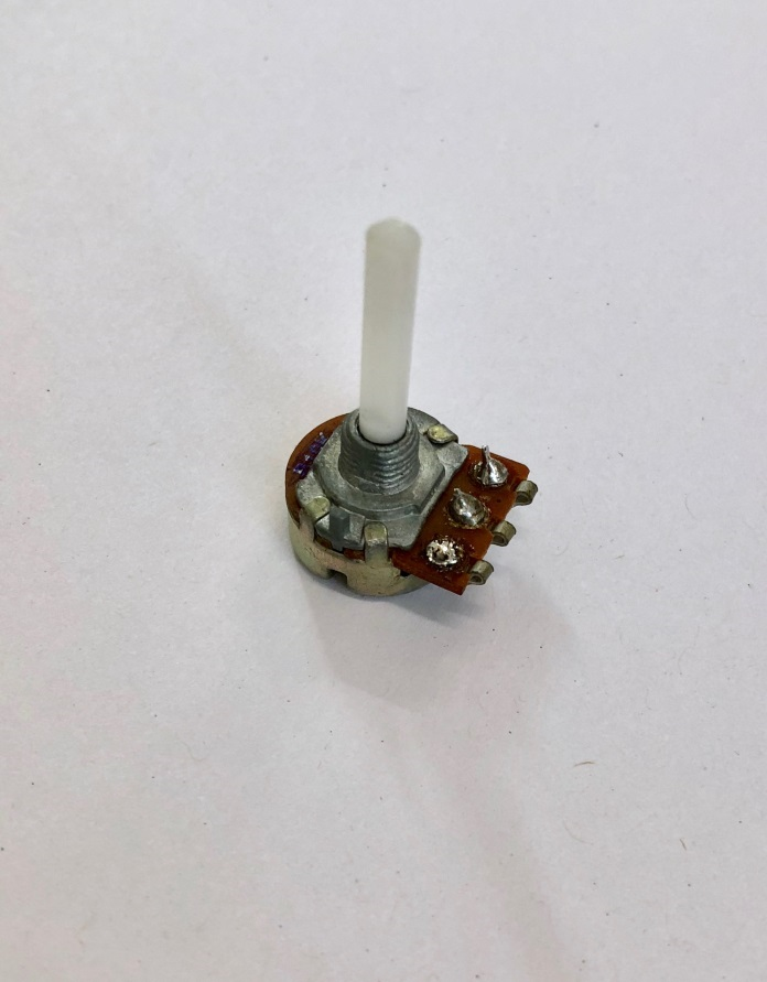
When the value of resistor change, then the output voltage from the resistor will also change. The interesting thing is that if the input voltage to the potentiometer is well known, then the output voltage from it can be used to infer where the shaft is. Let's see how:
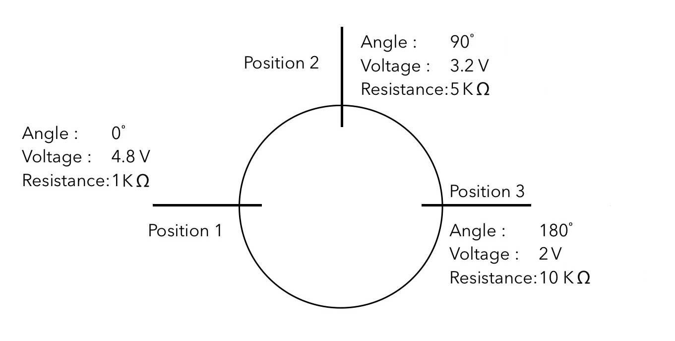
Now, let's say at a position of 0 degrees, the output voltage for the potentiometer is 4.8V; when we move it up to 90 degrees, the value changes to around 3.2V, and upon turning entirely 180 degrees, the voltage reduces to a mere 2V due to the change in resistance.
Without really looking at the shaft of the potentiometer, we can easily derive that if the voltage output from the resistor is 4.8V, then the shaft must be at a position of 0 degrees. Similarly, we can say that it is at 90 degrees if the voltage is 3.2V and at 180 degrees when the voltage is 2V.
Here, we have just plotted three points, but for any given point on the potentiometer, there would be a very specific resistance corresponding to it. Through this we can precisely calculate where the shaft of the potentiometer would be. Now, let's put it in an interesting combination:
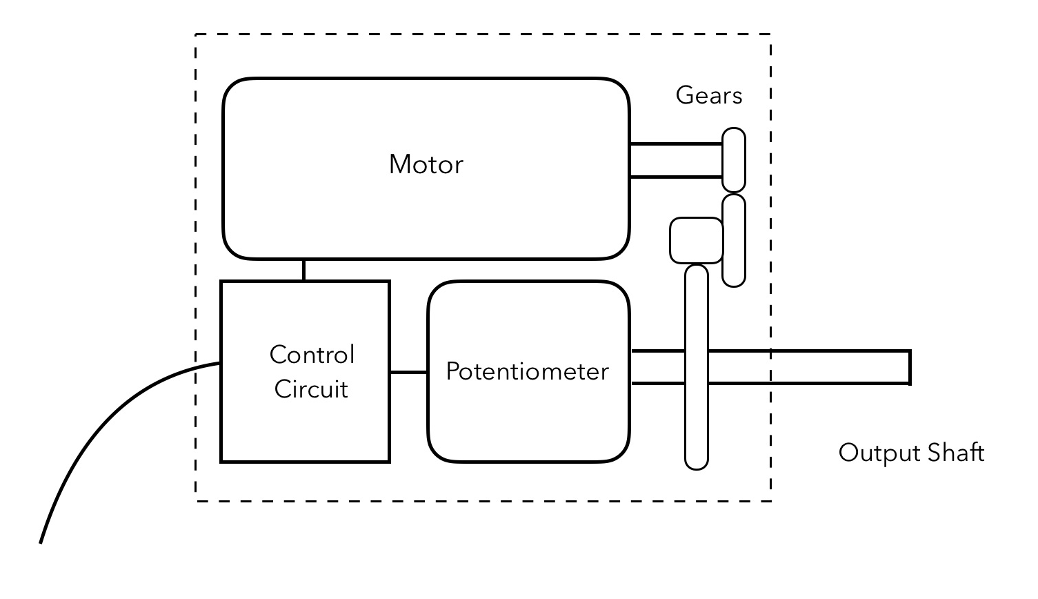
Now what we have is a motor coupled with potentiometer through multiple reducing gears that will reduce the speed of the motor and increase the torque. Further at the final gear, a shaft is mounted outward to the body coupled with a potentiometer.
So as you learned, the potentiometer will be able to sense at which angle the output shaft is pointing. The potentiometer is then connected to a control circuit that takes the reading from the potentiometer and further guides the motor on how much more to move to reach the goal position. Due to this closed loop arrangement in which the control circuit knows where the shaft is, it could calculate how much it has to move the motor to reach the goal position. Hence, this arrangement is able to turn the output shaft to any given position precisely.
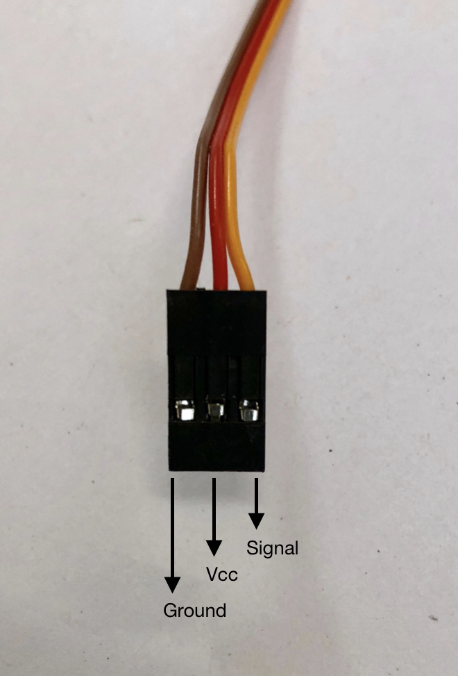
This arrangement is typically known as a servo motor. Throughout the robotics industry, it is one of the most widely used hardware to control precise movements. Essentially, there are three wires going into the control circuit—VCC, ground, and signal. The signal line will receive the data from our Raspberry Pi, and upon receiving, it will do the necessary motor movement to make the shaft reach the desired position. An image of a servo motor is as follows:

These can start from being extremely inexpensive, around $4 to $5, but they can go up to thousands of dollars. But what really decides the pricing of these servo motors? There are several factors that we need to keep in mind while choosing a servo motor, but the most important of it is torque.
Torque is a basically a turning force by which a motor can turn the output shaft. This is measured usually in kg·cm or N·m. Now what does this actually mean? Let's see the following diagram:

Let's say in the preceding diagram, we have a motor that has a torque of 10 kg·cm and the rotor attached to it is of 1 cm. So, it should be able to pull up a weight of 10 kg perpendicularly up from the ground. However, when we change the radius of the rotor to 2 cm, then the weight that can be lifted gets halved. Similarly, if the radius increases to 10 cm, then the weight that can be lifted would only reduce to 1 kg. So basically, the weight that can be lifted would be torque/radius.
But for most of our purposes, we would not be using a mechanism as shown previously, so let's look at the next diagram to see how the calculations can be made:

Now, let's say we have a shaft of length L and a load at the extreme edge of the shaft. For ease of calculation purposes, we would consider the weight of shaft to be negligible. Now if the servo is having a torque of 100 kg·cm and the length of shaft (L) is 10 cm, then by simple calculation, the load that we can pick up would be 100/10 = 10 kg. Similarly, if the length increases to 100 cm, the load that can be lifted would reduce to a mere 1 kg.
OK then; we have had a good amount of exposure to servo motors. Now the question is how do we control a servo motor? As I mentioned, there are different types of servo motors that are available that can be addressed by various means. However, the most common one used for hobby purposes is a digital servo motor. These servo motors require PWM, and based on the duty cycle of PWM, the angle of the shaft changes. So, let's see how it happens.
Typically, most of these servos have a frequency of 50 Hz. So basically the length of every pulse would be 1/50 = 0.02 seconds or in other words 20 ms. Further, the duty cycle that can be given to theses servo motors can be 2.5% to 12.5%, which basically means pulse width of 0.5 ms to 2.5 ms. Now let's see how it works:

As you can see, when given a duty cycle of 2.5%, the shaft gets down to the minimum position of 0 degrees, and when the duty cycle is increased to 7.5%, the shaft goes to the middle position of 90 degrees. Finally, when the duty cycle is increased to 12.5%, the shaft goes to the maximum position of 180 degrees. If you want any position in between, then you can simply choose the PWM corresponding to it, and it will change the position of servo to the desired angle.
But you may be thinking what if we want to take it beyond 180 degrees? Well, good question, but most of the digital servos only come with a range of 180 degrees of rotation. There are servos that can rotate completely its axis, that is, 360 degrees; however, their addressing is slightly different. After this chapter, you can pretty much go ahead check out any digital servo motor's data sheet and control it the way you want.
All right, enough of theory; it's time to do some fun. So, let's go ahead and set up the hardware and control a servo by our bare hands! Connect the servo to Raspberry Pi as follows:
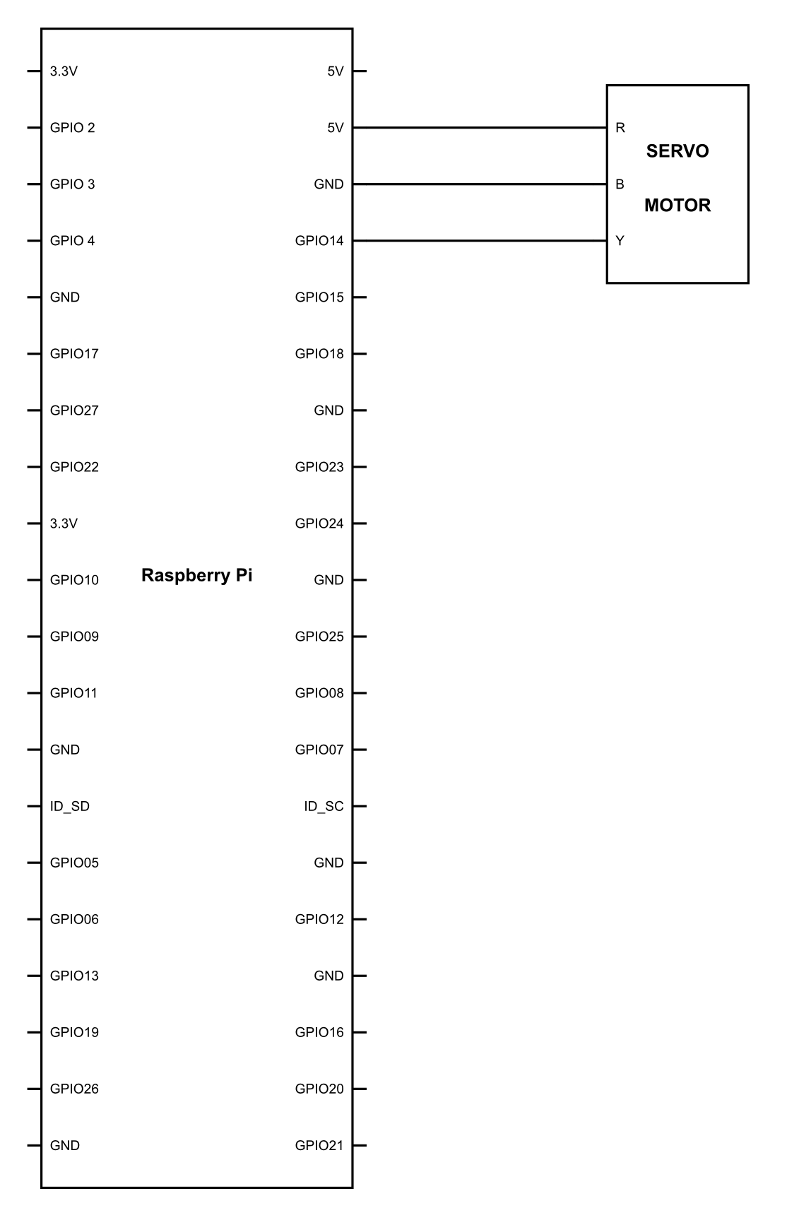
The color coding of the wires is as follows:
Next, we need to upload the following code and see what happens:
import RPi.GPIO as GPIO
import time

GPIO.setmode(GPIO.BCM)
GPIO.setup(14,GPIO.OUT)

pwm = GPIO.PWM(14, 50)
pwm.start(0)

while 1:

        pwm.ChangeDutyCycle(2.5)
        time.sleep(2)

        pwm.ChangeDutyCycle(5)
        time.sleep(2)

        pwm.ChangeDutyCycle(7.5)
        time.sleep(2)

        pwm.ChangeDutyCycle(10)
        time.sleep(2)

        pwm.ChangeDutyCycle(12.5)
        time.sleep(2)
As soon as you run this program, you will see the shaft of the servo moving from left to right, making steps at 0 degrees, 45 degrees, 90 degrees, 135 degrees, and finally 180 degrees.
Let's see what we have done in the program to achieve it:
pwm = GPIO.PWM(14, 50)
pwm.start(0)
With the line pwm = GPIO.PWM(14, 50), we have defined that GPIO pin number 14 will be used for PWM and the frequency of PWM will be 50. We have used the line pwm.start(0) in earlier chapters as well. It basically sets the PWM pin to 0 that is no duty cycle:
        pwm.ChangeDutyCycle(2.5)
        time.sleep(2)

        pwm.ChangeDutyCycle(5)
        time.sleep(2)

        pwm.ChangeDutyCycle(7.5)
        time.sleep(2)

        pwm.ChangeDutyCycle(10)
        time.sleep(2)

        pwm.ChangeDutyCycle(12.5)
        time.sleep(2)
No all the earlier program is in the while loop, that is, it will be executed over and over until the program is forced to quit. Now the line pwm.ChangeDutyCycle(2.5) sends a PWM of 2.5% duty cycle to the servo motor. This will simply turn the servo motor to 0 degree angle. Next, we use the good old time.sleep(2), which we all know would halt the program that line for two seconds.
The same cycle is being repeated with different PWM values of 5%, which would turn the shaft to 45 degrees, 7.5% for 90 degrees, 10% for 135 degrees, 12.5 % for 180 degrees. It's a very simple program that would clear out our basics of the servo motor.
So by now, you have learned how to control servo motor and move it in the direction in which we want. Now, let's go a step ahead and change the code slightly to make the servo run smoothly:
import RPi.GPIO as GPIO
import time

GPIO.setmode(GPIO.BCM)
GPIO.setup(14,GPIO.OUT)

pwm = GPIO.PWM(14, 50)
pwm.start(0)

i=2.5
j=12.5

while 1:
        while i<=12.5:
                pwm.ChangeDutyCycle(i)
                time.sleep(0.1)
                i = i + 0.1

        while j>=2.5:
                pwm.ChangeDutyCycle(j)
                time.sleep(0.1)
                j = j - 0.1
What happened when you uploaded this code in your Pi? You would have noted that the servo is swiping from left to right very smoothly and then right to left. We have done a very simple trick; let's see what it is:
        while i<=12.5:
                pwm.ChangeDutyCycle(i)
                time.sleep(0.1)
                i = i + 0.1
Here, we are running a loop that will run till the time the value of i<=12.5, as we have defined earlier in the program the value of i has been set to 2.5 as default in the starting of the program. Thereafter every time the code runs, the duty cycle is set to the value of I , the program halts for 0.1 seconds and then the value of i is incremented by a value of 0.1. This is increasing the duty cycle of the PWM. Once the value reaches 12.5, the loop exits.
The entire PWM range we have is 2.5% to 12.5%, so we have a space of 10% to play with. Now if we map it to the angular rotation of the servo motor, then every percent of PWM corresponds to a change of 180/10 = 18 degrees. Similarly, every 0.1% of the change would result in a change of 180/100 = 1.8 degrees. Hence, with every 0.1 seconds, we are adding duty cycle by 0.1%, or in other words, we are increasing the angle by 1.8 degrees. Hence, we find this action extremely smooth.
We are doing the similar thing in the next portion of the program; however, we are doing it for the reverse motion.