3
Animatronics
Every kid wants to build a robot. No matter what materials are at hand, from cardboard to empty soda bottles to brooms, if a kid starts to build, there’s a decent chance that the shape that emerges will be named robot. With that type of enthusiasm and access to real, powerful components, the perfect robot should emerge spontaneously, right?
Using context to create focus is a key to any successful work with young or inexperienced roboticists. Left to describe their dream robot, most kids will describe some fantastical blend of Baymax, Optimus Prime, and Gundam Wing. Vision that expansive can inhibit, rather than inspire, when it hits the hard reality of servo motors.
This group of projects focuses kids’ attention on a “simple” branch of robots that move and respond to the environment for the benefit and enjoyment of an audience. Kids can think of these as interactive tops, preprogrammed puppets, or scaled-down versions of audio-animatronics developed by Walt Disney Imagineering. While working on the Mission to Mars ride at Disneyland during college, Rick got firsthand experience with Disney’s audio-animatronics brilliance. Both vintage and newer Disneyland rides include this trademarked Disney technology.
First, we’ll build some puppets that make random movements to introduce several different operations, and then move on to more advanced creations that actually respond to user input. Each section will explain the specific hardware needed for movements and sensing. Having a handful of custom-made RJ25 cables using the instructions in Chapter 1, “Kit to Classroom,” will be very handy for these projects. The short 6″ cables that come with the mBots will seriously limit your creativity. With cables 1′–3′ long, you can really accomplish almost anything you dream up. For all the projects in this chapter, the box-creature bodies are just a starting point and will surely turn into whimsical creatures as kids’ imaginations go wild.
Materials
Tools
Craft Supplies
Electronics
For Adding Sensing and Movement
- Ultrasonic
- Distance
- Motion
- Light
- Line-following
- Sound
- Touch
- Servos and linkage arms (aka, servo horns)
- LEDs
- Motors
Puppet Movement without Sensors
For the first few projects in this chapter, we’ll build some creations that light up, rotate, and spin, but don’t react to user input. Later on, we’ll build some things that actually respond to user input using specific sensors.
Project: Random Light-up Eyes Using RGB LED Sensor
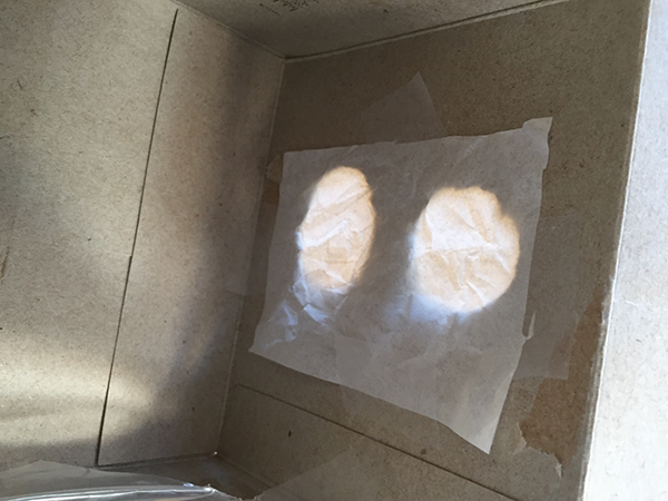
In this first project we’ll create a basic cardboard box head with cut-out eyes and an RGB LED inside.
- Select a box that is approximately 5″× 5″× 5″—I used an empty tissue box. Open the box so you can get inside.
- Cut some eye holes out with a hobby knife and then add some tissue paper on the inside to cover the holes and diffuse the light.
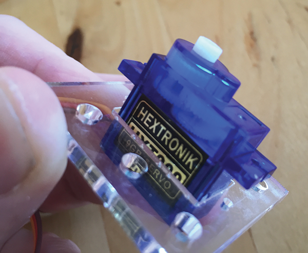
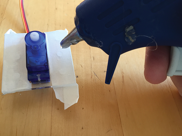
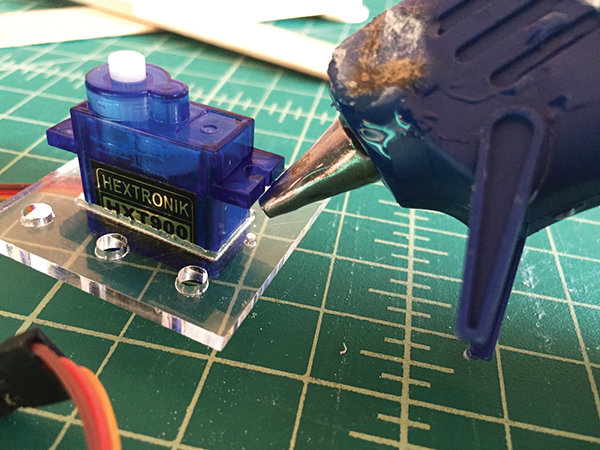
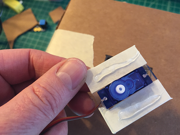
- Put masking tape on the bottom part of the LED sensor. (Whenever you’re going to use hot glue on a sensor, add tape first to prevent damage to the electronic parts.)

- Add hot glue to the tape on the LED sensor and stick it inside the box.
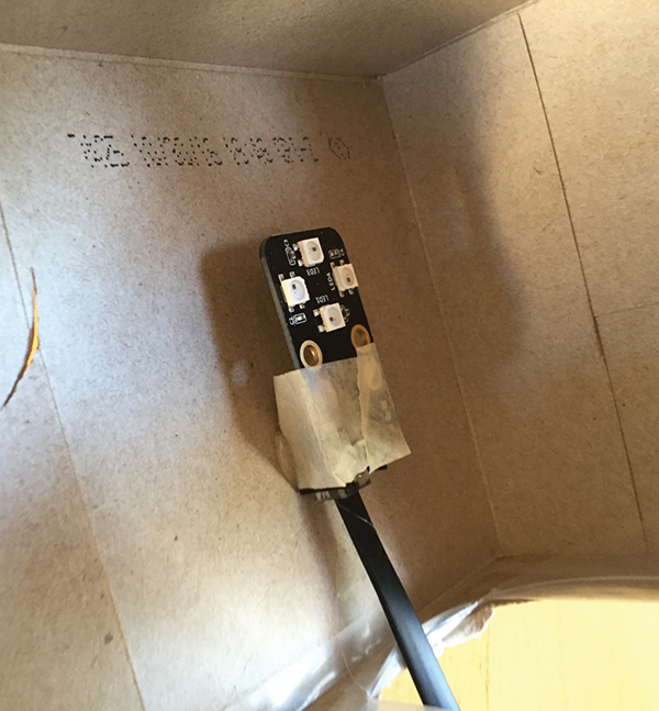
- Thread the RJ25 cable out the bottom of the box and attach the cable to port 1 on the mCore.
- Connect the mCore to your computer and open mBlock. Write and run the following program:
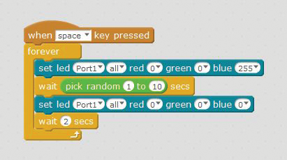
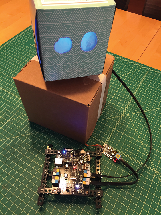
This will create randomly flashing blue LED eyes that run forever after the space bar is pressed. This is just a starting point, so now it’s time to get creative by modifying this code to customize the colors and blinking patterns.

Project: Head Turning Randomly Using 9g Servo and RJ25 Adapter
If you are using a lightweight “head” like the tissue box for this project, 9g servos will work, with some modifications. If you are moving a heavier object, you might need a bigger servo, like a Hitec HS-311, which has a higher torque. For $3–$5, you can also purchase micro servos with metal gears that are less likely to be stripped by too much weight or force.
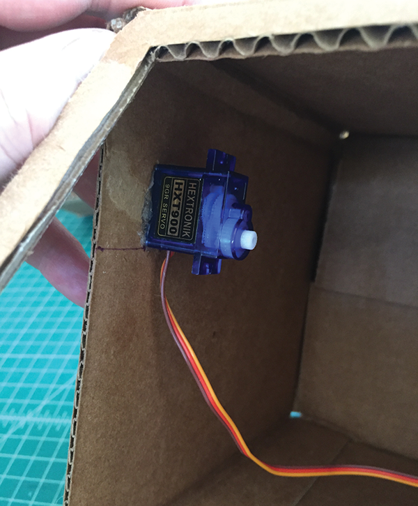
Mount and Wire the Servo
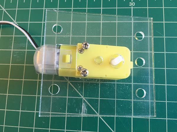
- First, cut a mount for the servo. If you have access to a laser cutter, download the template file from www.pngrrocketworks.com/instructions/make-mBots, and use it to cut a mount from acrylic. If you don’t have access to a laser cutter, you can also use the full-scale PDF, which can be downloaded from the same location, to hand-cut a servo mount out of a material of your choice. Slip the servo through the mount and attach it using hot glue.
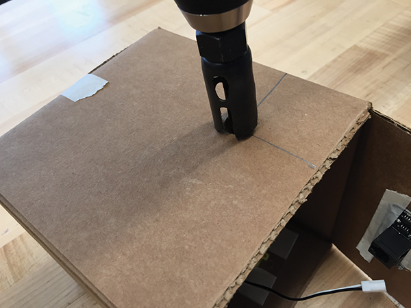
- Next, cut a hole about ¾″× 1¼″ in the center of the box to fit the servo and push the servo up through the hole in the box.
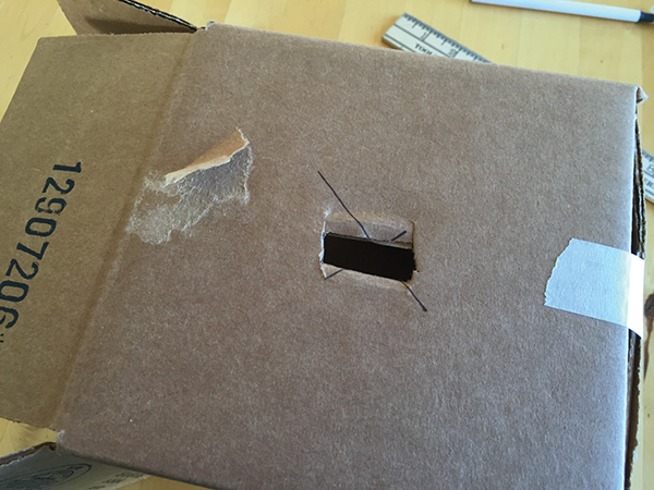
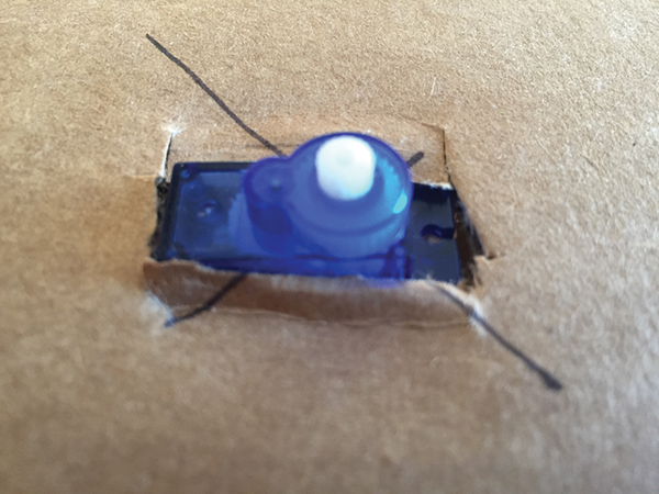
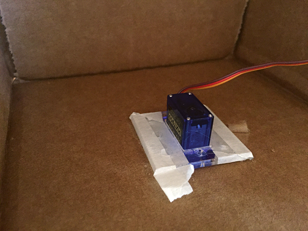
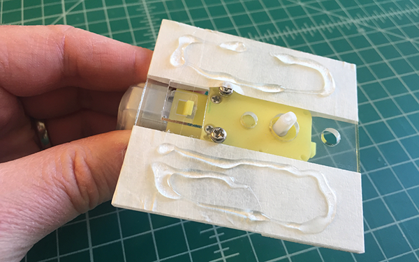
- Once you’re sure the servo fits, put tape over the servo mount and glue it to the inside of the top of the box.
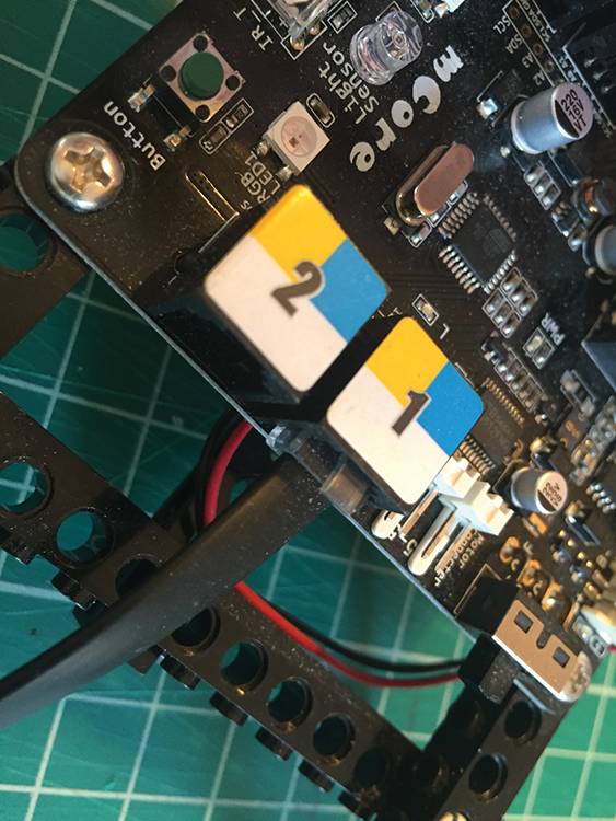
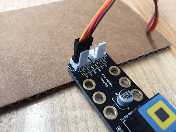
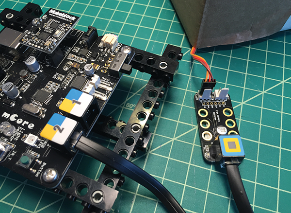
- Feed the servo wires out the back of the box and tape the box shut. Then, connect the servo to the Makeblock RJ25 adapter. The RJ25 adapter allows you to connect two servos to one port on the mCore. For this project, let’s attach the servo to slot 1 using the following guidelines:
- Orange or yellow: S1 (signal)
- Red: VCC (power)
- Brown or black: GND (ground)
Building the Servo Arm
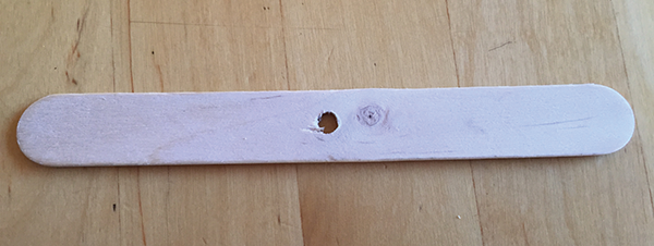
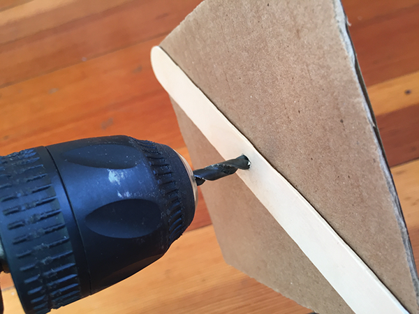
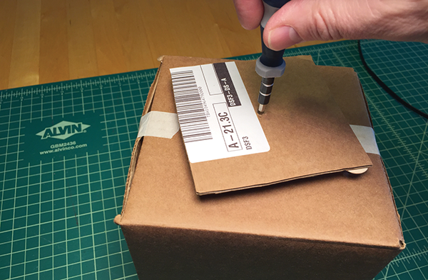
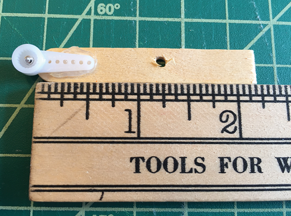
- Mark the center of a large craft stick and drill a ¼″ hole.
- On a piece of cardboard, trace whatever you are using for your creature’s head, and then cut out the shape. I’m using the same box I used for the LED eyes project because I’m going to use this as my creature’s head.
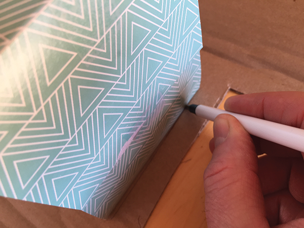
- Hot-glue the craft stick to the piece of cardboard, then drill through the hole in the stick again and on through the cardboard. Depending on the size of the box used for the head, you may need to trim the craft stick.
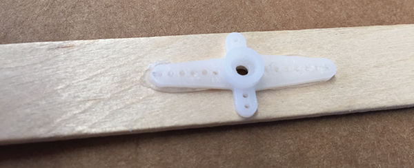
- Next, take the largest arm that came with your servo and hot-glue it onto the stick, with the side that attaches to the servo facing up. You need this to stick really well, so use plenty of glue, but not so much that it goes inside the hole.
We’ll set this aside for now until we have the servo connected to the mCore and calibrated.
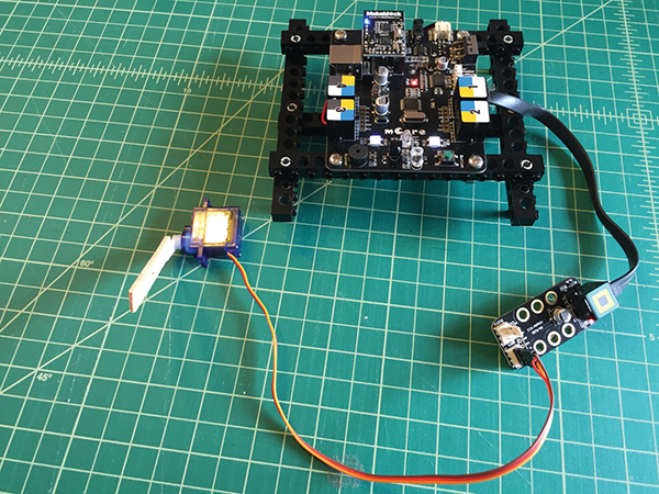
Wiring to the mCore
- The servo should already be connected to the RJ25 adapter. Now connect the RJ25 adapter to port 2 on the mCore using an RJ25 cable. (It’s connected and programmed for port 2 because you may want to use port 1 for the LED eyes.)
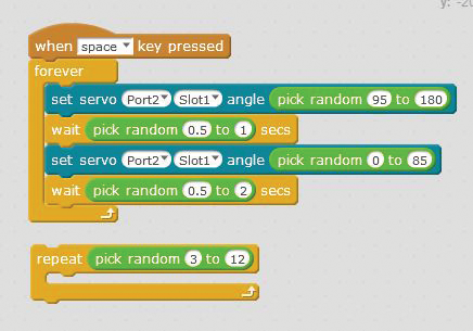
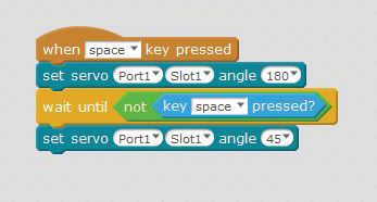
- Connect your mCore to your computer and write the code shown in the following image using mBlock. This will make the servo turn from 0 to 180 degrees randomly when the space key is pressed. If you want the servo to move for only a set period of time, you can swap the Forever control out for Repeat, as shown here.
Attach the Head to the Body
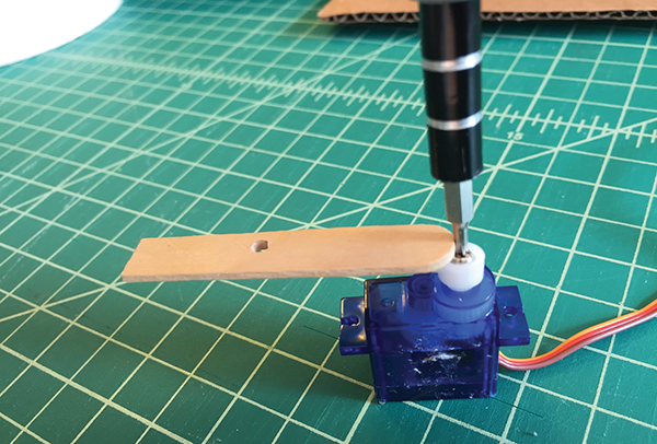
- Once the mCore is connected and programmed, attach the stick and cardboard control arm to the top of the servo and carefully screw it in place using the screw supplied with the servo.
- Then, attach the head to the servo platform using tape.
Combining the LED Eyes with the Moving Head
- If your LED eyes are still inside the head, you’ll need to route the cable out and to the mCore in a way that the cable does not interfere with the operation of the moving head.
- Now, using one of your custom RJ25 cables that’s at least 2′ long plug your LED eyes into port 1 of the mCore and combine the two programs. Now you’ve got a randomly moving head and blinking LED eyes!
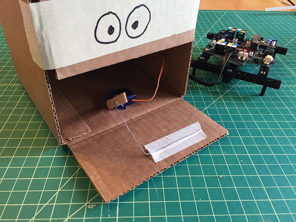
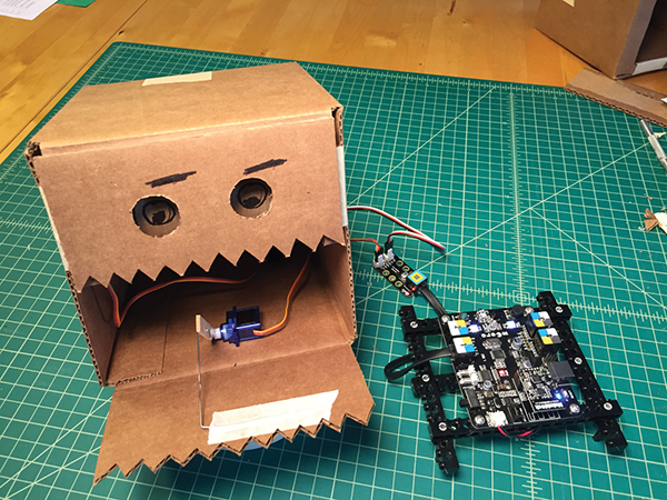
Project: Opening Mouth Using a 9g Servo and an RJ25 Adapter
This puppet in this project is made using a box, one servo, a single-sided servo arm, a small craft stick, and a large paper clip to operate the mouth flap.
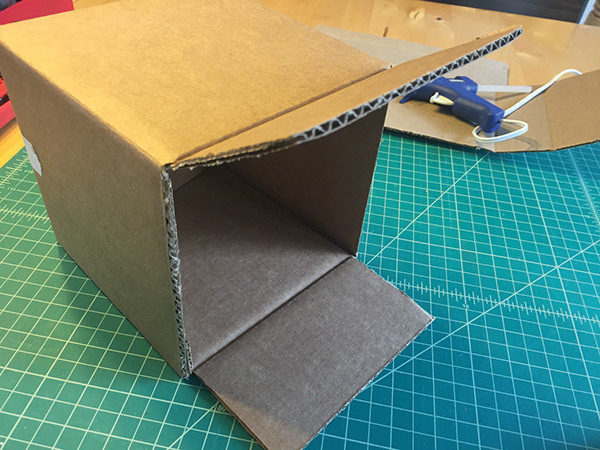
We’re going to start with a cardboard box and use one of the flaps as the mouth. For this example, we’re using a 6″ × 6″ × 6″ box from Uline.
- Lay the box flat and, on one end, cut off the two flaps opposite of each other.
- On the side you didn’t cut, tape the four flaps closed with a strip of masking tape.


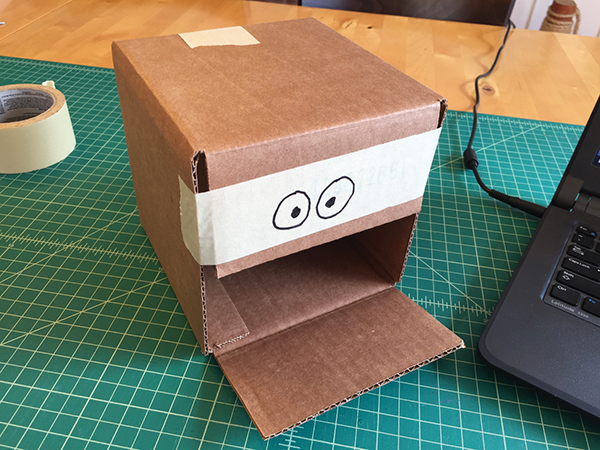
- On the other side, tape just one flap down and draw eyes. The bottom flap will be our mouth.
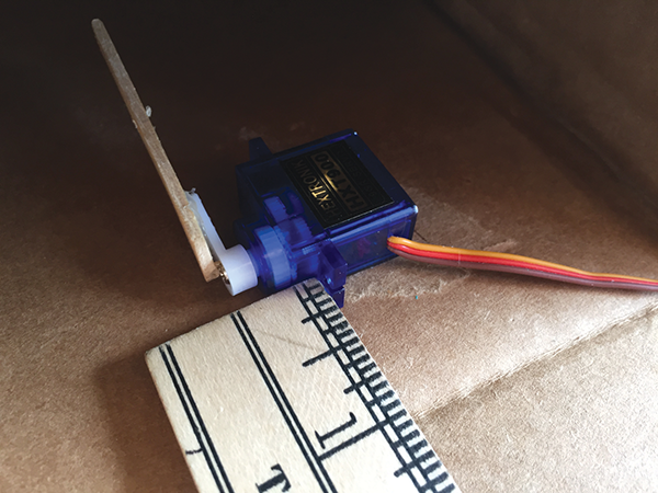
- Grab a 9g servo and select the longest single-sided servo arm. We’ll be extending the arm by hot-gluing a craft stick to it. Cut the small craft stick down to about 2″, drill a small hole 1¼″ from the end of the stick, and then glue the servo horn to the stick with hot glue.
- Press the servo arm and stick extension down onto the servo top, and turn it all the way to the left, with the servo oriented as shown in the following image. Reposition the stick extension (also shown here), then screw the servo arm into place using the short self-tapping screw provided with the servo.
- Connect the servo to the RJ25 adapter. Refer to the earlier project in this chapter, “Head Turning Randomly Using 9g Servo and RJ25 Adapter,” for details. Next, plug the servo into slot 1 and then mCore port 1.
- Program and run the following.
The servo should rotate between the two positions.

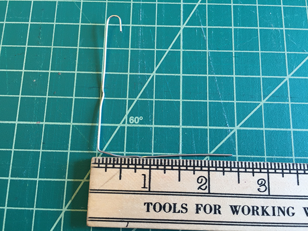
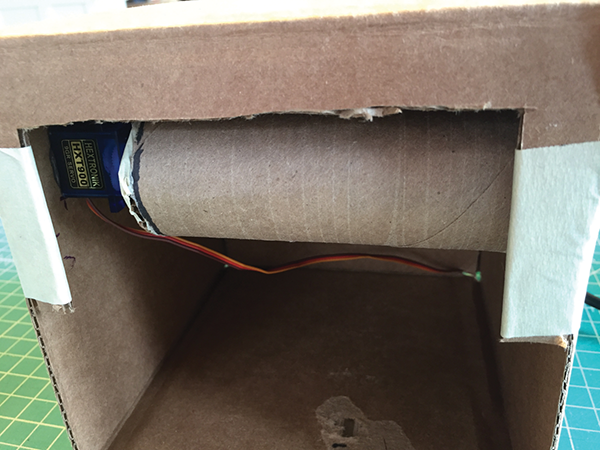
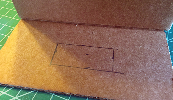
- Using needle-nose pliers bend the jumbo paper clip into the shape shown in the following image, with 2½″ legs on both sides.
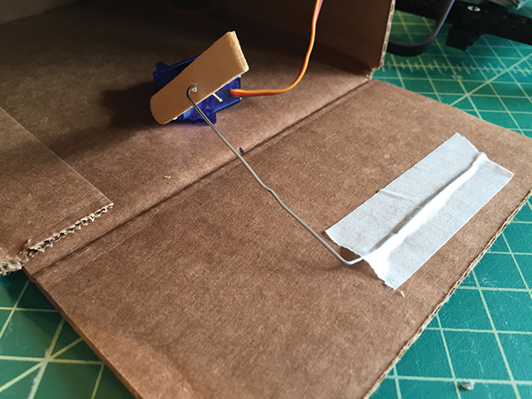
- Measure 1″ from the front of the box, and mount the servo to the inside of the box. Hot-glue it directly to the cardboard to make sure it’s flat, as shown in the following image.
- Hook the paper clip through the hole in the wooden craft stick, then rotate the servo toward the front of the box. Then tape the paper clip down to the flap.
- Your mouth should now open and close using your space bar as the trigger.
- Once you know your mouth is working correctly, you can remove the tape and replace with a generous amount of hot glue.
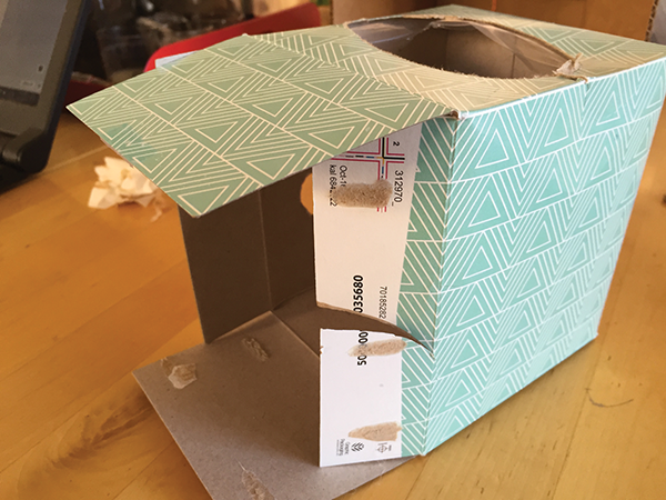
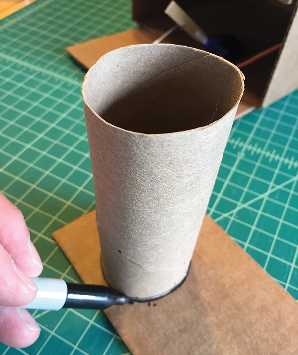
Project: Rotating Eyes Using a 9g Servo and an RJ25 Adapter
For this project, you’ll be using the same box from the previous moving mouth project along with a cardboard toilet paper tube, servo horn, and masking tape.
- Take the tape with the drawn-on eyes off the flap of the box you built in the previous project.
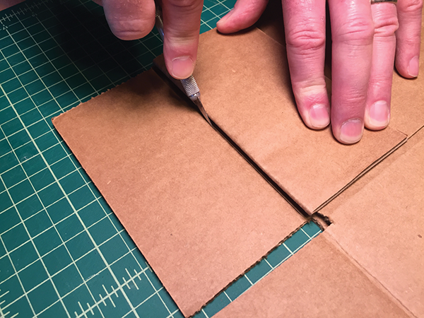
- Flip the box over, and then cut out the bulk of the flap with a hobby knife, leaving a ½″ border on three sides of one flap, as shown in the following image. This is where you’ll be building your rotating eyes. Save the scrap, because we’ll be using it in a future step.

- Take a cardboard tube, trace a circle around it on another piece of scrap cardboard, and then cut out that circle.
- Hot-glue the servo horn to one side of the cardboard circle, with the part of the servo horn that attaches to the servo as close to the middle as possible.

- Now hot-glue the circle onto one end of the cardboard tube.

- Measure and make a mark on the upper-inside-left of the box 2¼″ down from the top and 1¼″ in from the front. Using a generous amount, put glue on the bottom of the servo and then glue the servo to the side of the box, lining up the bottom-right side of the servo with your mark.
- Now, flip your box over and tape down the flap opposite the moving mouth on each side, as shown here.
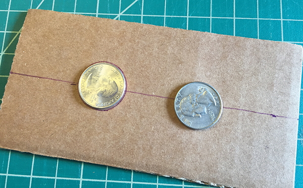
- On one of the scrap pieces of cardboard, measure 1 ½″ down on both sides and draw a connecting line. Center two quarters on the line, draw a line around them, and then cut them out. This is where the rotating eyes will line up.
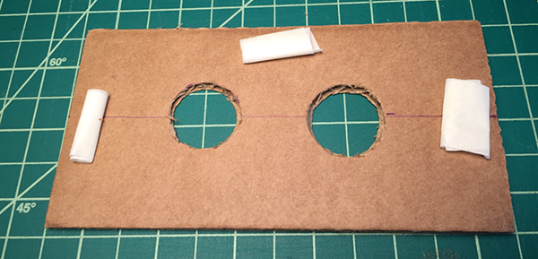
- Roll up some tape, as shown in the following image, and attach to the box over the rotating tube.
- Write the code on Scratch and then run the program. The eyes will rotate between three positions.
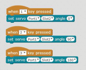
- Using a pencil, draw the numbers 1, 2, and 3 on the tube through the openings you cut for the eyes that correspond with the three positions. You may need someone to press the 1, 2, and 3 key on your keyboard while you’re numbering the three positions.
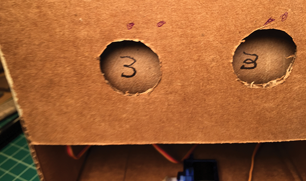
- Remove the cardboard with the eye holes, and draw in three different eye shapes with a Sharpie. Again, you may need to have someone hold the 1, 2, and 3 keys on your keyboard while you’re drawing in the eyes with the Sharpie.
We also added a serrated edge to both sides to look like a mouth. Have fun customizing your own!
- In Scratch, you can combine the rotating eyes and mouth movement using the following code.
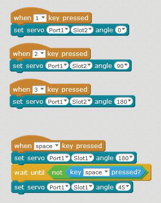
By pressing the 1, 2, and 3 keys, you’ll move the eyes into the different positions. The space bar will open and close the mouth.
Puppet Movement with Sensors
The projects so far in this chapter have been preprogrammed for random or set movements without sensors. Now we’re going to add some interactivity where your creature senses the environment and responds according to your program.
Project: “Feeding” Your Creature Using the Light Sensor
With this project, we’ll use a light sensor that senses when your creature is “fed” and triggers a couple of motors to spin your creature’s ears.
For this project you’ll need two geared motors, a light sensor, and an LED. We’ll attach the two motors inside the cardboard box, attach wheels on the outside, and then add some whimsical ears to the wheels. Then we’ll affix the light sensor and LED inside the “mouth.” When we “feed” the creature a piece of cardboard food, the ears will spin!
- Starting with a fresh 6″× 6″× 6″ box or similar, tape the back of the box closed, and then cut off the side flaps on the other side, as shown.
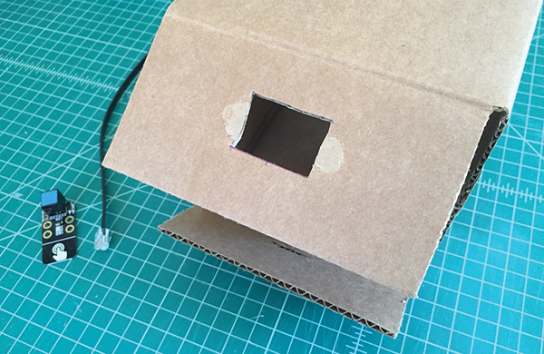
- Cut a ¾″× 2″ hole in the bottom flap.
- With a 1½″ hole saw, cut a hole in the upper corner of each side, as shown. I measured 2″ from the top and 2″ from the side.
- If the hole looks messy, you can clean it up with a hobby knife.
- It’s easier if you mount the motors to a laser cut motor mount first. Laser-cut a mount out of acrylic using the template files available at the book’s website. The additional holes in the mount are sized so that you can connect the motors to LEGOs or other Makeblock accessories.
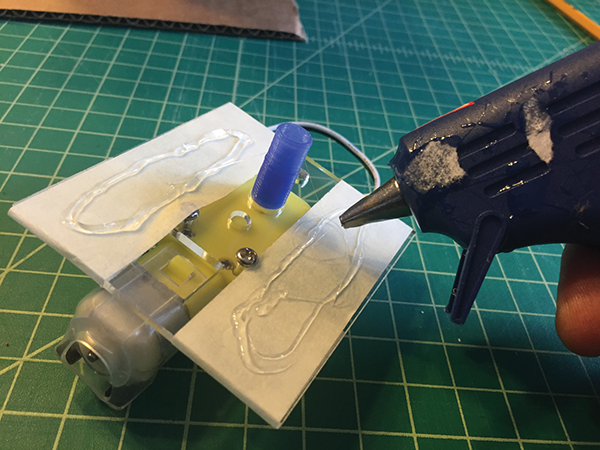
- Put masking tape on the acrylic motor mount so that it’s easy to remove later, and then add hot glue on top of the masking tape.
- Position the motor mounts inside the box with the motor hubs centered inside the holes. We’ll add the white plastic wheel hubs later.
Now repeat steps 5–7 with a second motor.

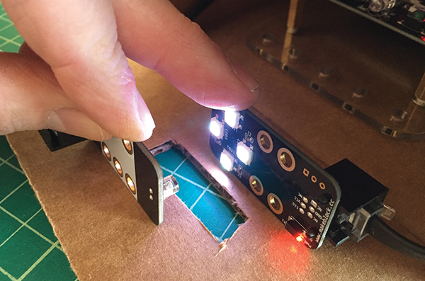
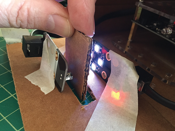
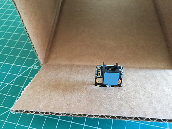
- The moving ears that you’ll be creating will spin around when the light between the RGB LED sensor and the Light sensor is blocked by a small piece of cardboard that is the creature’s “food.” Once you have the LED sensor and Light sensor positioned, you can tape them in place. Then connect the RGB LED to port 1 of the mCore and the Light sensor to port 3 of the mCore. The motors can be connected to M1 and M2.
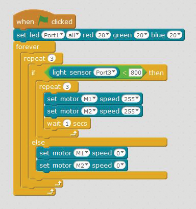
- Code the following in mBlock and send to your mCore. The code will turn on the LED, then trigger the motors (M1 and M2) when the light going to the light sensor is interrupted.
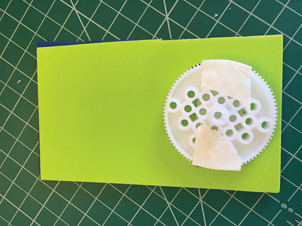
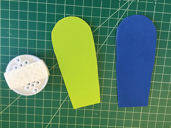
- Now we’ll add some fun ears to the wheel hubs using foam sheets. Cut the ears out of foam, apply masking tape to the plastic wheel hubs, and glue the ears on with hot glue.
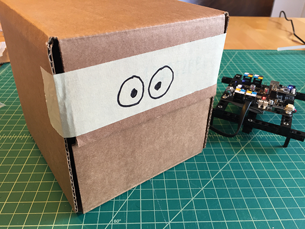
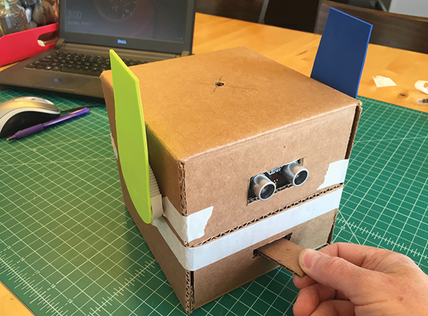
Now when you “feed” your creature by passing a cardboard disk through the mouth, the ears will spin. The creature will look like the one in the following picture. The creature also has an Ultrasonic sensor mounted on the front that will be part of the next project.
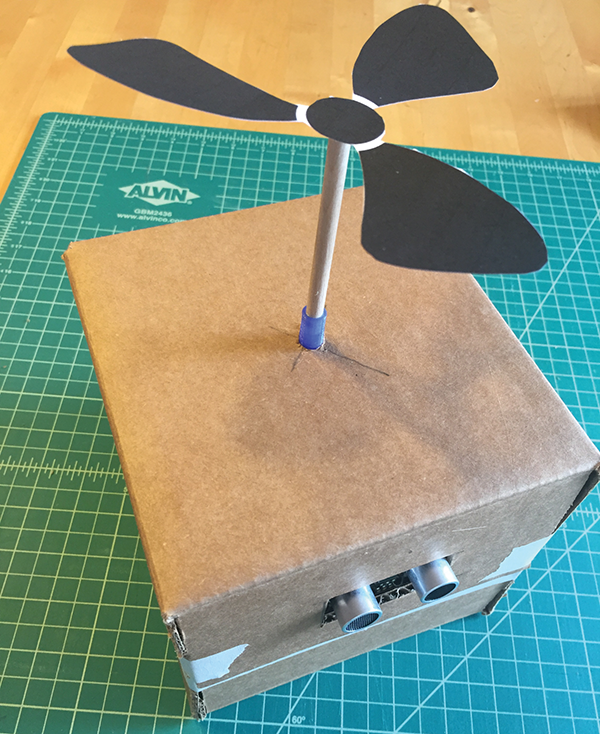
Project: Propeller Spins with Ultrasonic Sensor
For this project, you’ll need the Ultrasonic sensor and one of the geared motors. When something or someone approaches your creature, a propeller on its head starts to spin!
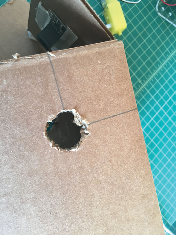
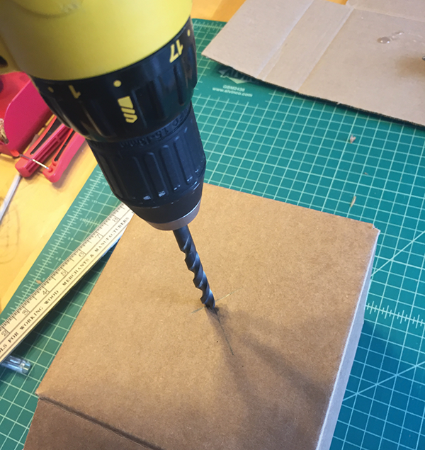
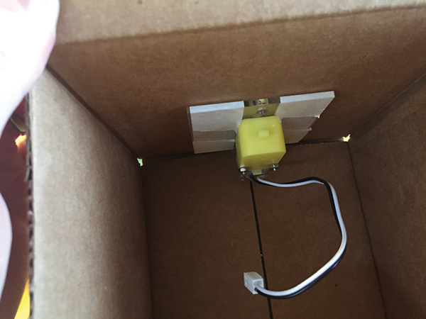
- Tape one side of a box closed. Then, drill a 5/16″ hole in the top center of a box.
- Mount the geared motor to a laser-cut, acrylic motor mount and cover the motor mount with masking tape. If you don’t have a laser cutter, you can cut the motor mount by hand using the full-size PDF template. You can make the mount from wood, cardboard, or soft plastic sheets.
- Print the dowel-to-gear-hub adapter on a 3D printer using the template, available on the book’s website: www.pngrrocketworks.com/instructions/make-mBots. Insert a ¼″ dowel connector into one end of the 3D-printed adapter and the other end onto the gear hub of the motor.
- Add hot glue to the tape on the motor mount and glue to the top of the inside of your box so the 3D-printed adapter sticks out of the top.
- Cut a ¾″× 2″ hole in the front of the upper front flap.
- Cover the Ultrasonic sensor with tape, apply hot glue, and attach to the inside of the flap. The tape will protect the sensor from the hot glue and allow you to easily remove it later.

- Mount the Ultrasonic sensor to the front of your box so that the “eyes” are exposed.
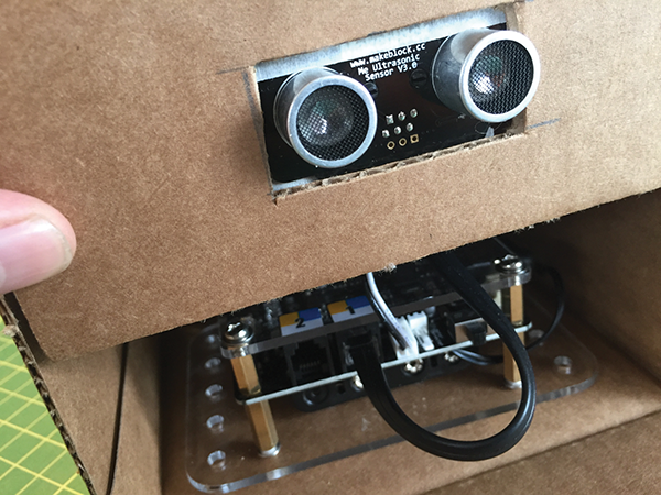
- Connect the Ultrasonic sensor to port 1 and the motor to M1.

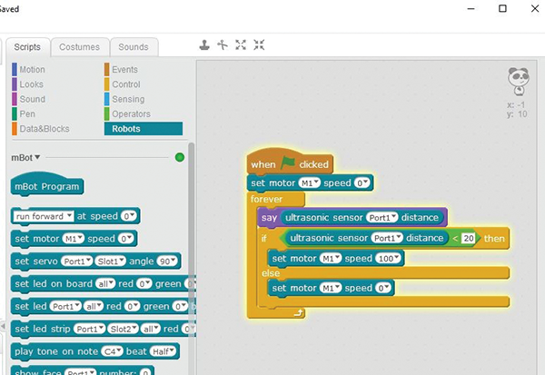
- Write and run the following code as a starting point. The Ultrasonic sensor will sense your movement and trigger the motor. You can adjust the distance at which the Ultrasonic sensor begins to react. Here it’s set at 20.
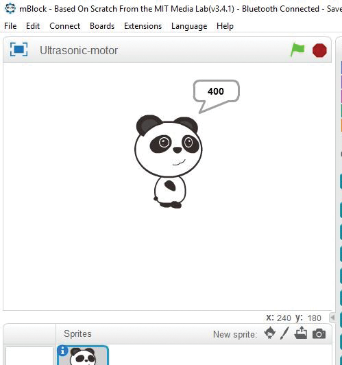
- If you add a Say block in Scratch (in the Looks script) to your Ultrasonic sensor, you’ll know it’s working when the data input changes in the Panda’s speech bubble. This one is set to 400. As you approach your creature, the motor should turn on.
- I added a 6″ long, ¼″ dowel to the 3D-printed adapter and attached a propeller printed on card stock to the top. This is where you can have fun customizing your creature with whatever your imagination can come up with!
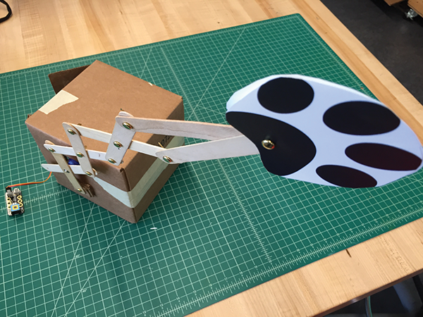
Project: Servo Arm with Paw Reaches Out When Motion Sensor Is Triggered
When someone approaches your creature, an arm linked to a servo will reach out.
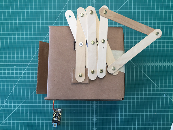
Sometimes the circular motion of a servo or motor isn’t exactly what you need for your creation. That’s where mechanisms come in! Hundreds of websites exist to show you how to turn a simple circular motion into other motions. While there are quite a few options, the one we’re going to focus on here is using a scissor linkage for a hand or paw that reaches out.
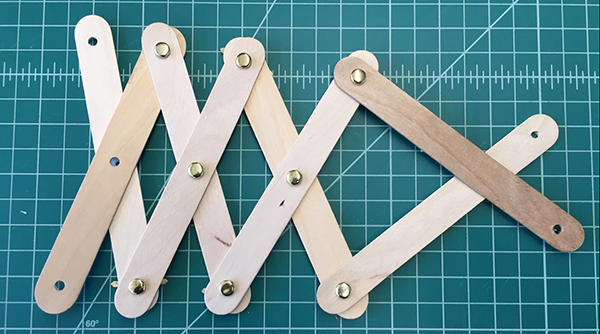
- Grab eight large craft sticks and some brads to build the grabber.
- Drill 5/32″ holes in the ends and middle of each crafts stick. It works well if you stack the sticks and drill them all together so you get the holes in the same place. Then insert brads, as shown. There should be one center hole with no brad.
- Decide which side of the box you want to attach the linkage to, or maybe you want two servos on each side! Cut a ¾″× 1¾″ slot in the box near the top center, as shown, then glue your servo to a laser-cut acrylic servo mount.
- Cover the servo mount in masking tape, and then add hot glue and tape inside the box with the servo centered.

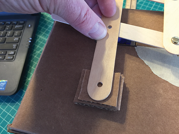
- Grab your servo linkage arm. Flip the scissor mechanism over and glue the servo linkage arm over the third center hole that does not have a brad. You can see pictures of linkage arm in the following image.

- Test-fit the servo horn onto the servo, then on the bottom end of the same craft stick as the servo arm, stack up several layers of scrap cardboard until the stick is about level with the servo, as shown in the following image. Mark the cardboard through the hole so you know where to place a brad.
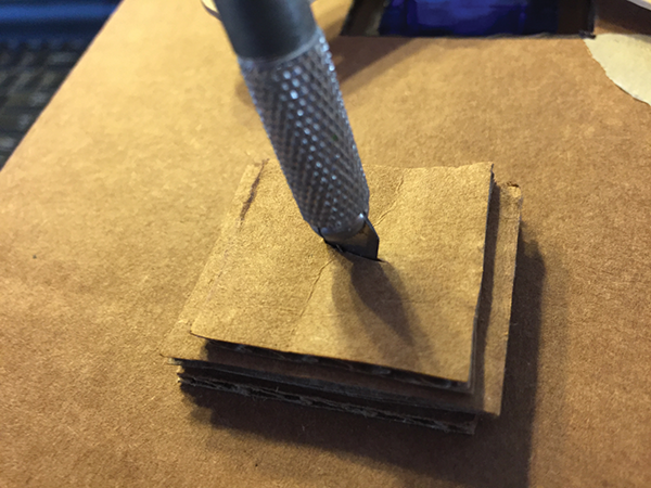
- Cut down through the layers of cardboard with your hobby knife.
- Connect the whole assembly using a brad.
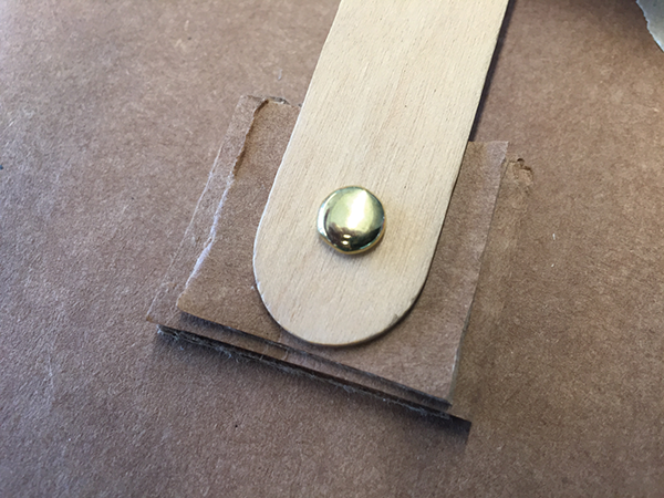
This is how it should look from the side.
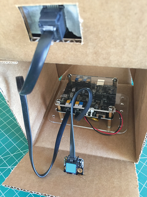
- Using Scratch, create the following program, which will allow the Motion sensor to trigger the servo. Push your Motion sensor through a hole in the front of the box and connect the servo to the RJ25 adapter. Next, connect the Motion sensor to port 4 and the RJ25 adapter to port 1 on the mCore.

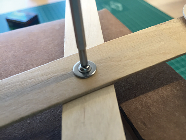
- Once you have the mCore programmed and the servo lined up, you can permanently attach the servo arm using a screw and washer.
- Now attach your claw, hand, or paw to the end of the scissor linkage and you’re ready to go!
You can find some additional linkage and mechanism resources from the brilliant folk at the Tinkering Studio at http://tinkering.exploratorium.edu/cardboard-automata.
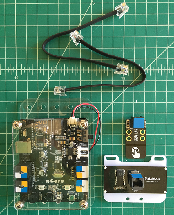
Project: Touch Sensor Triggers Scrolling Message
In this project, you’ll make a message display when your creature is “petted”! We’ll use the Touch sensor and an 8 × 16 LED Matrix display to make this happen.
- Gather the components shown in the following image.
- Grab a box, lay it flat, and cut off the two flaps opposite each other.
- Mark a 1½″× 1″ hole in the top flap and cut out the rectangle with a hobby knife. The LED Matrix will fit here.
- In the middle of the bottom flap, cut a 1″ wide slit with a hobby knife. The Touch sensor will slip in here.
- Add masking tape and then hot glue to the back of the LED Matrix.
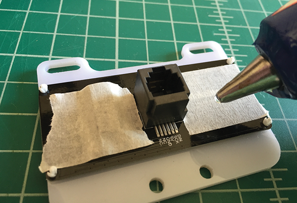
- Plug the LED Matrix into port 2 on the mCore and the Touch sensor into port 1.
From the front it should look like the following.

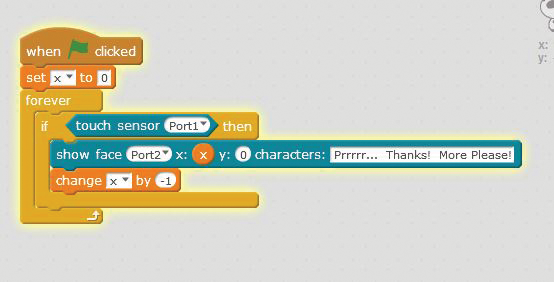
At this point, loading the program onto your mCore requires a bit more of an explanation (see the section in Chapter 1 titled, “Updating the mBot”). If you turn on your mCore and you hear three tones, you have the default program loaded. The default program includes all the files for your IR remote, line-following, and Ultrasonic sensor programs. These take up a lot of space and do not include the code needed to run the Touch sensor. You need to connect your mCore to your computer using a USB cable, open mBlock, and connect using whatever com port is available by going to the Connect menu, and selecting Serial Ports. Once you’re connected, select Upgrade Firmware on the Connect menu and it should go through the upload process to load the software needed for all the sensors, including the Touch sensor. Now, when you boot up your mCore you should just hear just one short beep.
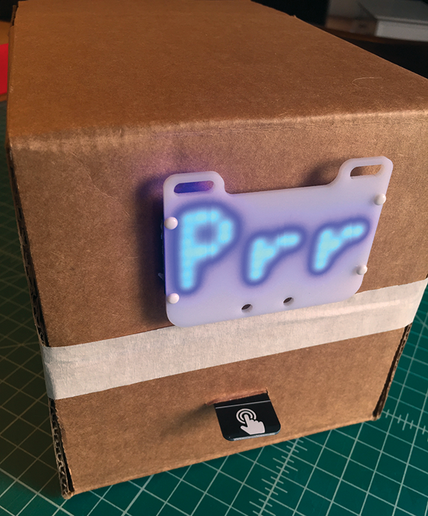
After upgrading the firmware and rebooting your mCore, connect your mCore via 2.4G serial or Bluetooth. Now, when the user triggers the Touch sensor by petting your creature, a message will appear on the LED Matrix! Each time you touch the Touch sensor, the message will start and stop. You have to keep touching the pad to see what the entire message says.
The projects in this chapter are just a starting point. Once you see how fun it is to set up and program sensors that trigger motors, servos, and digital readouts, you’re limited only by your imagination. I’ve used a 6″ × 6″ × 6″ box for most of the projects in this chapter, but you can use whatever you have available, or what works for your particular project. One thing I’ve discovered: when you give kids lots of creative supplies like colorful foam sheets, cardboard tubes, boxes of various sizes, feathers, pipe cleaners, wood sticks, and other craft supplies, their minds and creativity come up with incredible things. The mCore and sensors provide the foundation for adding interactivity to any creative endeavor.