5
Robot Navigation
Robots can navigate in a variety of ways. Autonomous robots navigate using programs that allow them to follow GPS coordinates, or sensors that allow them to navigate in response to their environment. Robots can also be operated by the user using remote control. We’ll look at several types of robot navigation in this chapter. We’ll also look at two add-on packs for the basic mBot kit, which are available for about $25. The mBot add-on Servo Pack and Interactive Light & Sound Pack have many additional brackets, studs, M4 screws and nuts, beams, additional sensors, and RJ25 cables, along with a wrench. These items are all handy for many of the projects in this chapter. The add-on packs are available through Amazon or on the Makeblock website (www.makeblock.com).
Robot Navigation Using Keyboard Commands
Connect your mBot to your laptop or tablet using Bluetooth or 2.4G serial wireless and write the code shown in Figure 5-1. With a Bluetooth connection, you can now control your mBot from across the room using the arrow keys.
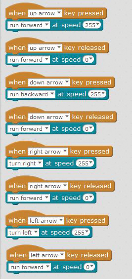
Figure 5-1: This Scratch code allows you to control your mBot with the up, down, right, and left keys on your keyboard.
Before we get started, though, I’ll share a quick note about speed. If the robot is moving too fast, drop the bot’s peak speed from 255 to 100. But remember: resistance in the gearing and the weight of the wheel combine so that lowering the values for speed too much may make you unable to move an assembled mBot. We’ve found that speeds less than about 70 aren’t strong enough to move the mBot from a dead stop, but if you give it a small push, it will keep moving forward.
Once you’re able to navigate using your arrow keys, you can devise all kinds of challenges using other mBots. The signals to each robot won’t interfere with each other, because Bluetooth connections are unique to each mBot. You can continue to use the code shown in Figure 5-1 in Scratch, but then add code to trigger actions based on input from other sensors. This way you can drive your mBot using the up, down, left, and right keys while your bot does other things.
Robotic Game Challenges
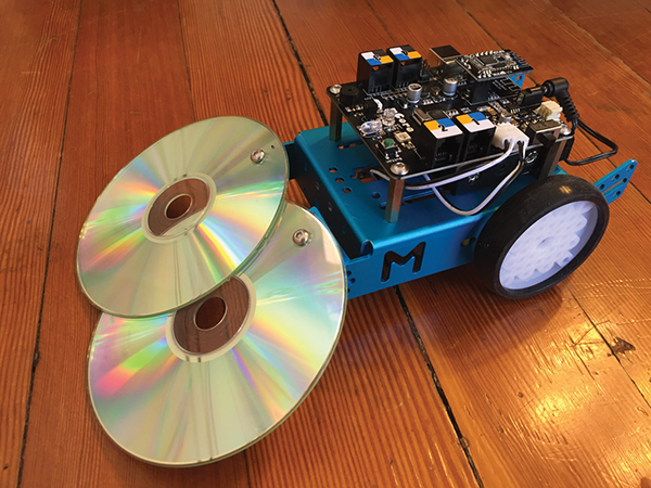
Once you are able to navigate your mBot using the arrow keys, you can begin creating your own Battle Bots! A popular game is Sumo Bots, where two or more bots battle it out inside a ring marked on the floor using tape. The last bot inside the ring wins! My students came up with a great design using old CDs to “scoop” their opponent out of the ring, as shown in Figure 5-2. We’ll start off with a few Sumo Bot defense and attack ideas.
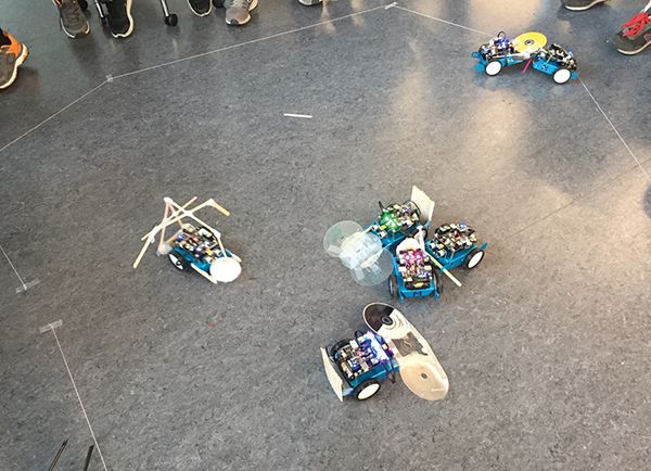
Figure 5-2: Here is a creative take on a Sumo Bot challenge from some of my middle school students.
CD Scoop
You can add a CD scoop by attaching old CDs onto the front of the mBot just off the ground to scoop your opponent out of the arena.
Parts
I’m trying to move my students beyond using gobs of tape for everything, so the following directions show the CDs being sturdily attached with drilled holes and screws.
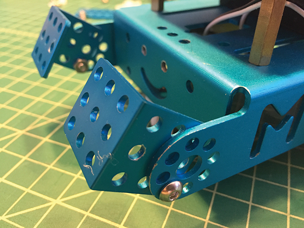
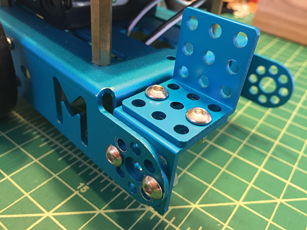
- Start off by attaching two right-angle L brackets to the front of your mBot using a 4M×8 screw and nut.
- Glue two old CDs together with a hot glue gun, then flip the mBot over and, using the holes as a guide, mark the CDs where you’ll drill a hole to attach them to the L brackets.
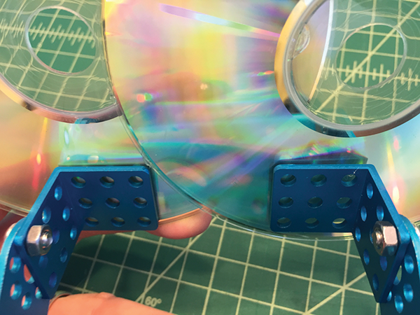
- Place a piece of scrap wood under the CDs, and then drill through the CDs where you marked the holes.
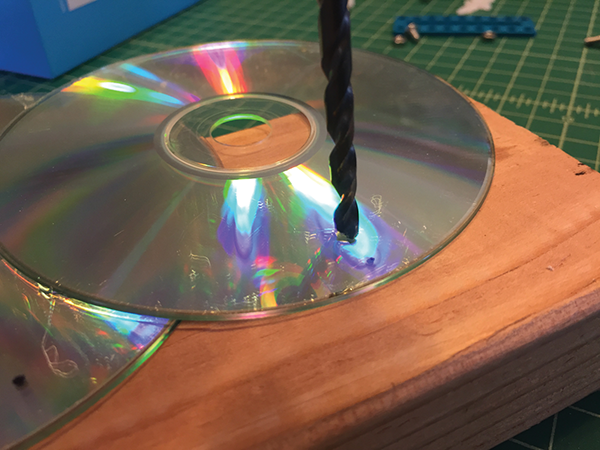
- Now put an M4×8 bolt and nut through the two CDs and tighten to hold them securely in place. Now you’re ready to scoop your opponent out of the ring!
Spear-Lowering Servo
A BBQ skewer/lance that can be lowered using a servo can be added as an attack mechanism.
Parts
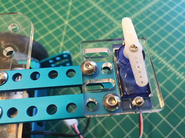
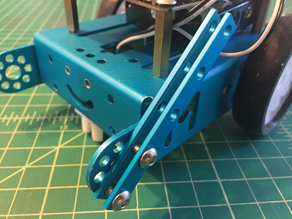
- Begin by attaching the two L brackets to the front of the mBot using four 4M×8 nuts and bolts, as shown in the following image. The L brackets, servo, and servo holder are included in the add-on Servo Pack.
- Next, attach the 9g servo to the laser-cut acrylic bracket using the small bolts and nuts that come with the add-on Servo Pack. If you’re using your own servo, download and laser-cut the file at www.pngrrocketworks.com/instructions/make-mBots. If you don’t have a laser cutter, you can print the full-scale PDF and cut by hand using cardboard or thin wood.

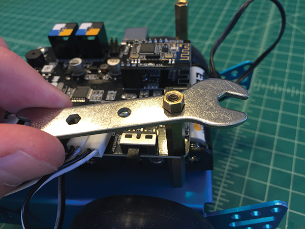
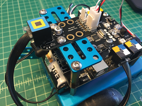
- Remove the M4 screws from the back posts, which holding the mCore to your mBot, and replace with the M4×25 brass studs.
- Now install the 9-hole blue plate to the brass studs with two M4 bolts, and then attach the RJ25 adapter to the blue plate with two M4 bolts and nuts. Plug the servo into slot 2 of the RJ25 adapter, and then plug the RJ25 adapter into port 4 on the mCore.
- Before you attach the servo to the front of your mBot, you need to center it. Connect the mBot to your computer using your preferred method (Bluetooth or 2.4G wireless serial). Then write the code to center the servo, shown in the following image, and send it to your mBot. You can use this code with any program to center a servo.

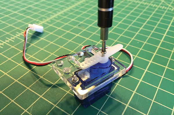
Now you’re ready to attach the servo arm to your servo using a very small Phillips head screwdriver and the tiny self-tapping screw that came with the servo.
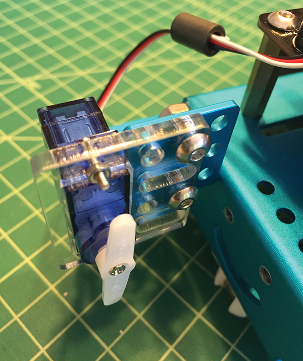
- Attach the servo to the right angles mounted on the front of the mBot using two M4×8 bolts and nuts.
- Line up a bamboo barbecue skewer with the servo arm and attach with two mini zip ties.
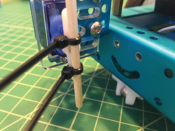
- Pull the zip ties very tight, and then clip off the ends of the zip ties with wire cutters.

- In Scratch, write the code shown in the following image and send it to your mBot.

I had to edit the angles a little bit to get the lance to a 45° angle, and then a 90° angle. The spear will lower to a 45° angle when the A key on a keyboard is pressed. It will return to the up position when the key is released. The spear will lower to a 90° angle when the S key is pressed, and then return again to the up position when the key is released.
Now you’re ready to joust with a cool skewer that can be raised and lowered using your computer. Safety is always important, so remember to wear your safety glasses when you’re working with sharp things.

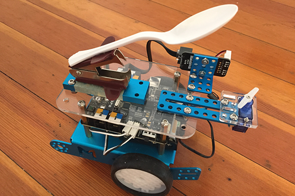
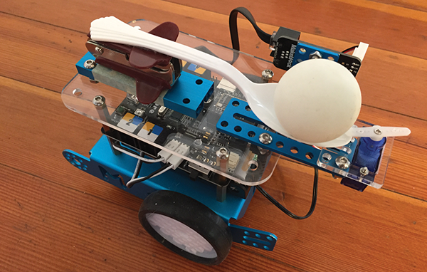
Catapult Ball Launcher
A whole different type of challenge is created using a plastic spoon and servo to hold the spoon back and then launch the ball like a catapult. This ball launcher could be used to knock down obstacles, shoot at targets, or aim for baskets.
Parts
Figure 5-3 shows all the supplies you’ll need.
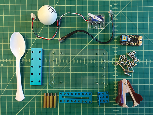
Figure 5-3: Here are all the supplies you’ll need for a ping-pong ball launch rig.
The clear acrylic piece shown in Figure 5-3 was used in Chapter 1 as a case for the mCore. Here, we’ll be mounting this platform to the top of your mCore to support the catapult mechanism and hold the electronics. Laser-cut files for the acrylic platform can be downloaded at www.pngrrocketworks.com/instructions/make-mBots, or printed out full scale from a PDF as a template for hand-cutting a material of your choice. Other key parts include a stiff plastic spoon and a standard staple remover.
- Remove the four M4 bolts that are holding on the mCore, replace them with the four brass studs, and tighten securely.
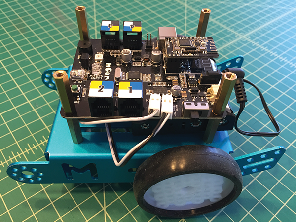
- Next, mount the acrylic platform onto the top of the brass studs using the four M4 bolts.
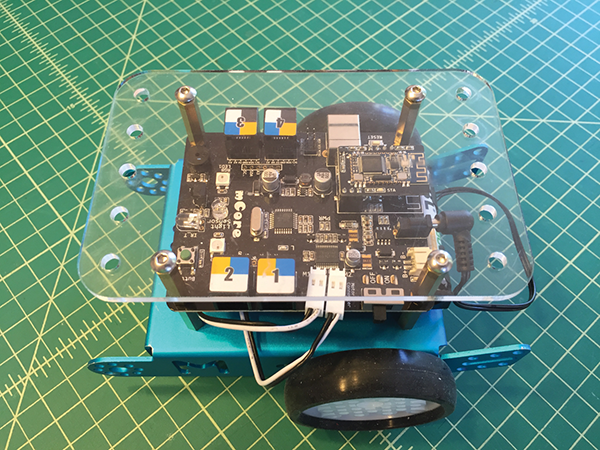
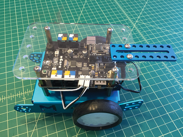
- Install the 9-hole blue plate to the back of the plastic platform on the second and third holes from the left, as shown in the following image.
- Mount the servo into the acrylic servo holder that came with the add-on Servo Pack following the instructions in the upcoming section, “Light-Emitting Head-Shaking Creature.”
- Next, use M4×14 bolts to bolt it down to the back of the 9-hole blue plate.
- Screw the RJ25 adapter to the L bracket using two M4 bolts and nuts.
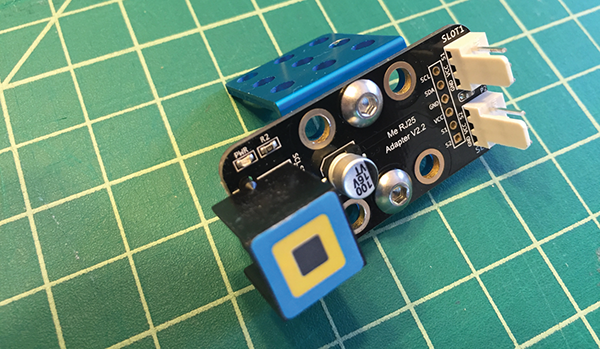
- Using M4 bolts and nuts, attach the L bracket to the rear of the acrylic platform in the two holes on the far right.

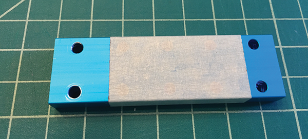
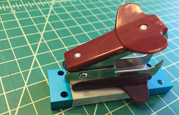
- Cover the double-wide, 10-hole beam with masking tape. We’re going to be hot-gluing the staple remover onto this part, so you’ll want to protect the metal. Make sure you keep two parallel holes on the ends exposed, since this is where you’ll attach it to the acrylic plate. It helps if you lay the masking tape on nice and smooth.
- Now add a generous amount of hot glue to one side of the staple remover.
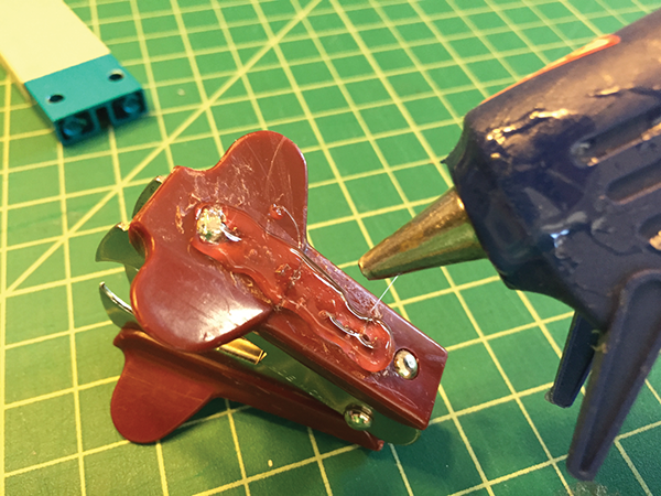
- Press the staple remover evenly, glue-side down, on top of the tape, lined up with one end of the plate, as shown in the following image. Make sure the holes are exposed, leaving enough room for the M4 bolts.
- Attach the staple remover assembly to the back of the acrylic plate with two M4×14 bolts and nuts, lined up as shown in the following image.
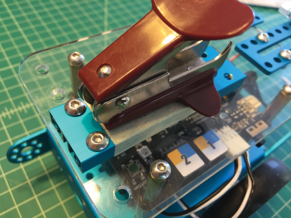
- Test-fit the plastic spoon on top of the staple remover. The spoon should line up a little off center of the servo arm. The servo arm should be able to securely hold the spoon down in the trigger position. The servo arm will rotate out of the way, which will trigger the spoon catapult arm.
- Once you know where the spoon should be placed (mark the end of the spoon with a Sharpie, if needed), add a generous amount of hot glue to the top of the staple remover and press and hold the spoon in place for 20 seconds.

- Connect an RJ25 cable to the RJ25 adapter and to port 3 on your mCore.
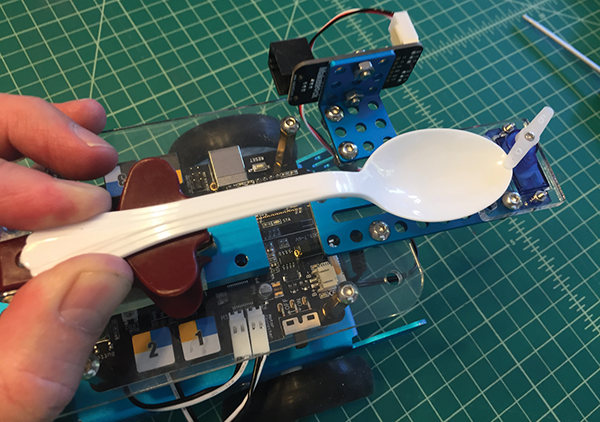
- Connect the servo to slot 2 on the RJ25 adapter. The nice thing about the servos that come with the add-on Servo Pack is that they only install in one direction so you always get them plugged in correctly. If you’re using a generic servo, follow the directions in Chapter 3, “Head Turning Randomly Using 9g Servo and RJ25 Adapter.” This is what your finished assembly should look like with the spoon catapult in the up position.
- Cock the spoon back and rotate the servo arm in place to hold it. Place your ping-pong ball in the spoon and now you’re ready to launch!
- Create the code shown in the following image in Scratch. This code is really simple, with your space bar being the catapult trigger.
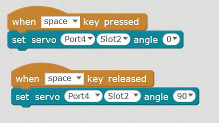
- Next, test your code to make sure the trigger works. You may need to modify your code or center the servo (see step 5 in the “Spear-Lowering Servo” section for centering directions) to get your trigger to work properly.
Now go set up some targets or create some challenges and fire away!
Robot with a 9g Servo Grabber on the Front
For this project, we’ll add an awesome 3D printed grabber mechanism powered by a 9g servo to the front of our mBot. By adding the grabber, which is controlled by your laptop, you’ll be able to set up all kinds of challenges and even go head to head with other mBots to move items around a battle arena or obstacle course.
Printing and Assembling the Servo Grabber
Hats off to Jon Kepler for coming up with this brilliantly simple robotic claw and posting it on Thingiverse. Download it at https://www.thingiverse.com/thing:18339 and print (printing will take about 35 minutes).
Parts
Along with these 3D-printed parts, you’ll need a micro servo (9g). The one shown in the following image uses metal gears but still costs only a couple of bucks. You’ll need the servo linkage arms that go with the servos, a 3×8 mm machine bolt, and a 3 mm nut. Once you have all the parts printed and gathered you’re ready to go!
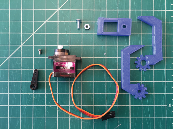
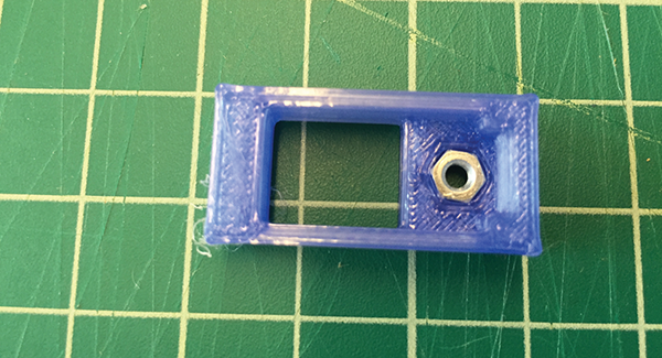
- Turn the 3D-printed servo box over and push the 3 mm nut into the hex-shaped indentation.
- With a pair of wire cutters, cut off the arm from the servo horn and then smooth out the cut edge with sandpaper.

- Place the servo box on top of the 9g servo, with the servo shaft positioned over the opening in the servo box.
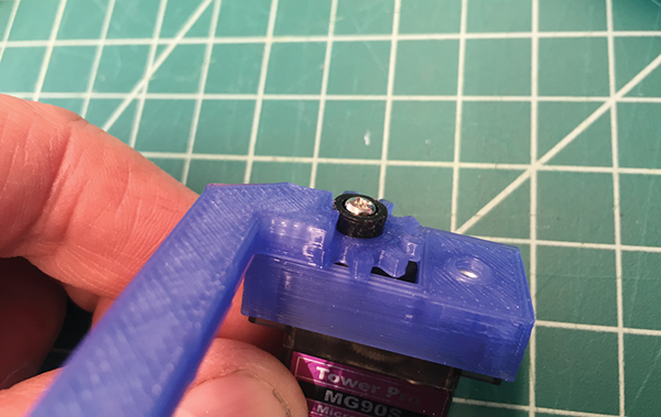
- Attach the right pincer to the shaft of the servo with the screw that came with it. Use the piece of the servo horn from step 2 as a spacer.
- Position the left pincer next to the right one with the gears interlaced.
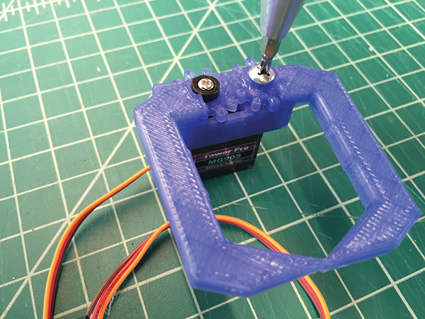
- Attach the pincer by pushing the 3 mm bolt through the nut and tighten loosely so the pincers can move. They should move in a grasping motion.
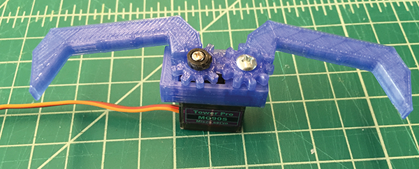
The principle behind the servo arms is very simple. One arm is directly connected to the shaft of the servo. The other arm is linked by gears to the first arm. When the servo shaft turns, the first arm rotates and, thanks to the gears, forces the second arm to move in the opposite direction, thus bringing the two arms together. Once attached to the mBot, the arms may need to be adjusted after you get the servo calibrated.
Attaching the Servo Grabber to Your mBot
Next, you’re going to build a bracket to attach your mBot to the grabber mechanism.
Parts
- Screw the aluminum L brackets included with the mBot Servo Pack onto the front brackets of the mBot chassis using the M4 bolts and nuts.

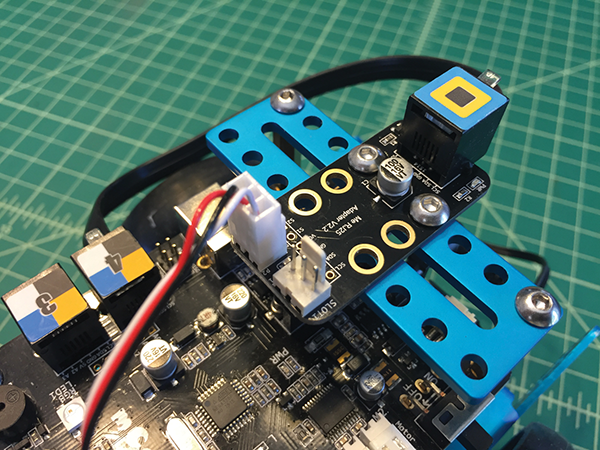
- Screw the 9-hole blue plate to the L brackets, as shown in the following image.

- Attach the servo grabber to the front bracket with a mini zip tie, and cinch it tight.
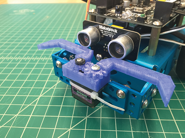
- Connect the servo to port 1 on the mCore using the RJ25 adapter. I attached the RJ25 adapter to the back of the mBot using some M4 screws and nuts. The wires can be neatened up using more mini zip ties or twist ties.
Here is the servo grabber in the closed position holding a piece of foam pipe insulation.
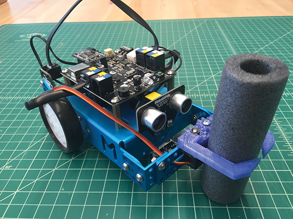
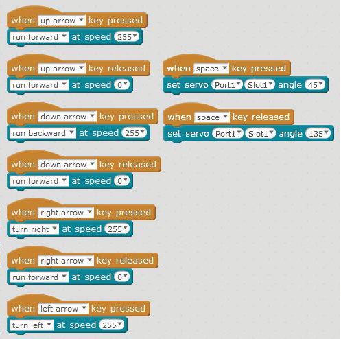
Write the code shown in the following image in Scratch. The code on the left controls the mBot using the up, down, left, and right arrows. The code on the right opens and closes the grabber claw using the space bar.
Light-Emitting Head-Shaking Creature
This project uses the add-on Servo Pack, which includes the following (also shown in Figure 5-4).
Parts
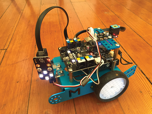
With the Servo Add-on Pack you can build a dancing cat, a head-shaking cat, or a light-emitting cat. For this project, we’ll be combining the light-emitting and head-shaking features, which creates a robot with a lighted LED “head” that can move back and forth using a servo.
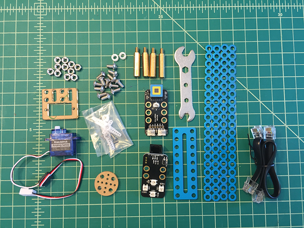
Figure 5-4: The Servo Add-on Pack
- Attach the 9-hole blue plate to the top rear of your mCore.
- Attach the RJ25 adapter and center the servo, as described in step 5 of the “Spear-Lowering Servo” section.
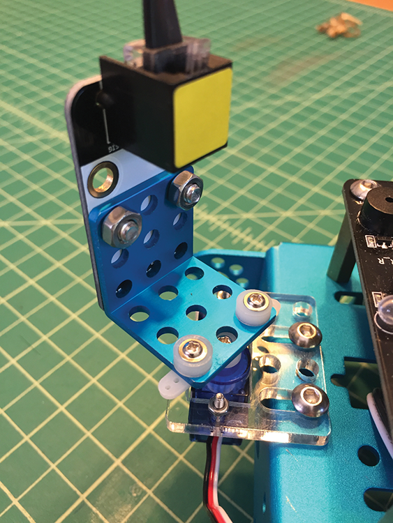
- Once the servo is connected and centered, attach the L bracket to the servo arm using the two self-tapping screws that came with the servo.

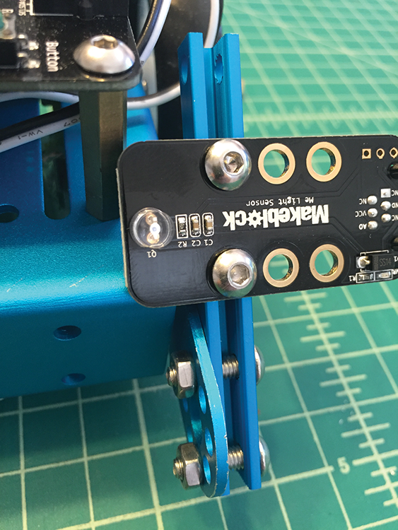
- Attach the LED sensor to the L bracket with two 4M×8 bolts and nuts, as shown in the following image. Make sure the sensor is attached in the top holes of the L bracket through the bottom holes of the LED sensor so that the sensor can rotate freely on the servo.

- Plug the RJ25 cable into the sensor. It should be positioned so that it comes out of the top.
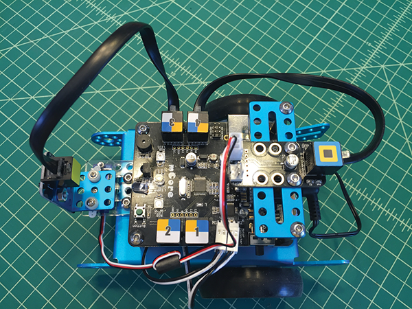
- Plug the other end of the RJ25 cable into port 3 on the mCore.
- Plug a second RJ25 cable into port 4 and plug the other end into the RJ25 adapter mounted on the back of the mCore.
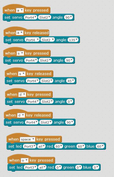
- Write the following code in Scratch. This will program the LED to turn on and off and move the light left and right using A and D keys, and re-center with S.
Light-Chasing Robot
For the following project, you’ll use the add-on Interactive Light & Sound Pack. You’ll be creating a bot that follows a flashlight using two Light sensors. The add-on Interactive Light & Sound Pack includes the following.
Parts
For this project, we’re going to build the light-chasing robot using some beams and the two Light sensors.

- Mount the double-wide two-hole beam to each side of the front of the chassis with two M4×14 bolts and nuts.
- Each channel is threaded inside, so you can screw the Light sensor into the channel using two M4×8 bolts.
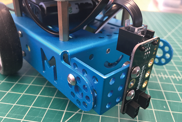
The following image shows both Light sensors mounted to the front.

- The RJ25 jack should be facing out. As you’re looking at the back of the mBot, plug one RJ25 cable into the jack on the right side and then into port 4, and then plug another cable into the jack on the left side and then into port 3.
- Now program the following code into Scratch and send it to your mBot.
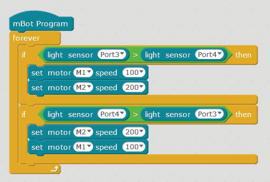
You’ll now have an mBot that follows the light from a flashlight, whether the light moves straight ahead, right, or left.
Maze-Solving mBot Using Standard Sensors
In Josh Elijah’s Makezine.com article, “Beginner Robotics: Understanding How Simple Sensors Work,” he describes the characteristics of true robots well: “For a robot to truly be considered a robot, it must be able to sense and affect its environment.” The article uses a robot operation called Sense, Think, Act. In a nutshell, this means the sensor senses the environment, the microcontroller thinks, (makes a decision about what to do), and then it acts (carries out the decision).
The next project, brilliantly conceived by Dani Sanz from Spain (juegosrobotica.es), illustrates robotic operation excellently. His website is translatable using Google and I’ve translated his Scratch code here. Dani’s project shows how globally the mBot platform reaches.
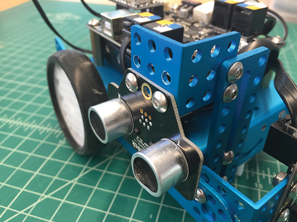
The Line Follower sensor and Distance sensor that come with the mBot kit are the only sensors needed for this maze-solving design. These sensors sense the environment, which in this case is a maze. The mCore thinks about what to do, and then carries out the decision. This feedback loop operates continuously from the time the mBot starts the maze until it finishes.
The mBot add-on Servo Pack comes with two L brackets, two plates, and plenty of M4 bolts and nuts, and they work well for this.
- Using an L bracket, mount the Line Follower sensor vertically instead of horizontally (which is how it’s used for line-following). Use one M4 screw and nut to hold the L bracket in place, and then add two M4 screws and nuts to secure the line sensor.
- With two M4 screws, attach a 9-hole blue plate to the front right side of the mBot, pointing up vertically. Next, add an L bracket to the plate, facing out. Now, attach the Distance sensor upside down to the bottom of the L bracket facing out on the right-hand side of the mBot. Plug the Ultrasonic sensor into port 3 of the mCore.
- Attach an L bracket to the front right of the mBot chassis using M4 screws and nuts. Plug the Line Follower sensor into port 2 and the Ultrasonic sensor into port 3 of the mCore.
- Write the following code in Scratch.
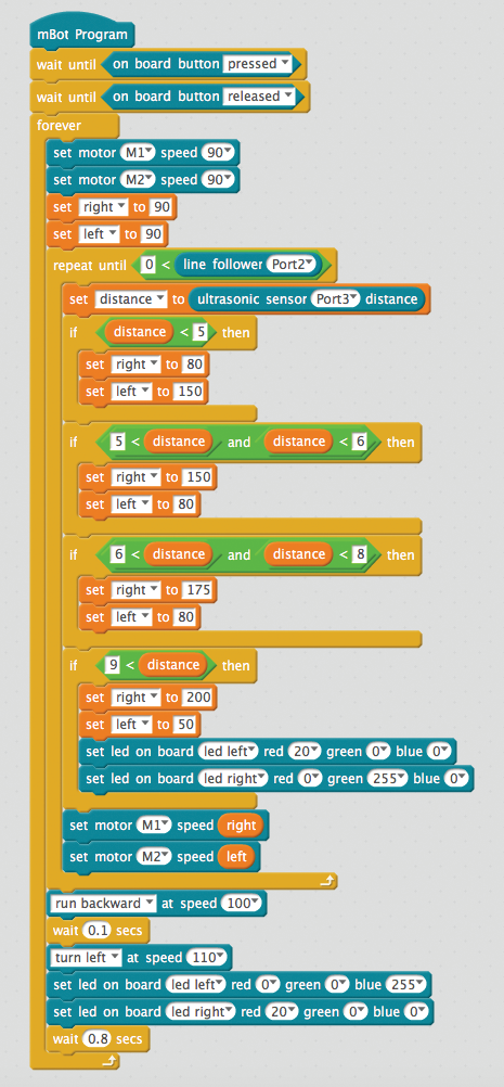
The following image shows the variables needed for the program.

- Next, create your maze! The maze shown in the following image is made out of foam pieces placed on the floor.
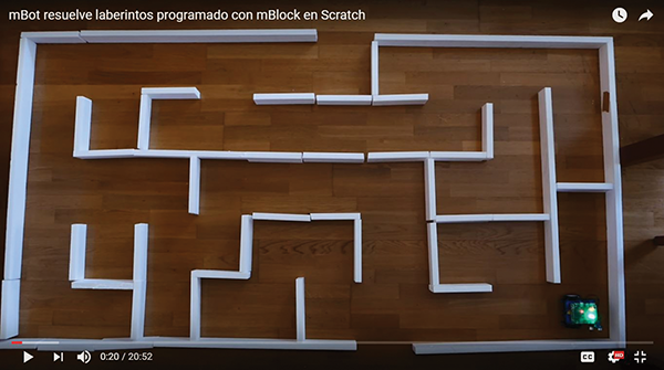
It’s possible to make your maze out of cardboard, foam, or any object you have lying around. Start off with a simple maze, and then move the walls around and add more to make it more complex. If everything is working correctly, the maze pieces shouldn’t need to be attached to the floor, because the mBot will never touch the maze walls. Kids will have a blast creating mazes for each other to solve using their mBots!
While this chapter has looked at many of the standard items offered by Makeblock like the add-on packs, the next chapter will really delve into how to use the mCore with off-the-shelf components like pumps, motors, and LEDs. Chapter 6, “Building Big and Small with mCore,” will also dive deeper into the workings of DC motors and how to connect standard DC motors to the mCore board in a way that works with many projects and many kids.