6
Building Big and Small with mCore
This chapter explores the flexibility of the mBot through the frame of dollhouse services—designing simple and complex features, considered part of “smart” environments, on a smaller physical scale. However, the adaptability of the mCore platform means that it’s entirely possible to scale up a clever idea from the dollhouse to the real world. On a small scale, we’ll work with water, small LEDs, and servos, and then show how to adapt those programs to make use of household lamps, fans, and aquarium pumps.
We’ll use the mCore to control several different devices. At the electrical level, these devices are mostly two-pole motors—sets of electrified copper coils pushing against magnets. The rotational force these components generate can be used to push water or air, or to spin a wheel or a propeller.
Harnessing DC Power
Brushed motors send currents to copper coils mounted on the spinning shaft, while brushless motors mount the coils on the stationary cylinder and spin a shaft covered with magnets. The differences in construction and scale can differ for particular applications, but the key point is that anything driven by a simple DC motor only needs a two-wire connection. Current flows through the motor circuit and generates spin. Most DC motors are non-polar, meaning that they will spin in either direction depending on the direction of electrical flow. However, if the DC motor is built into a fan or pump, the larger device may be built in a way that requires a particular polarity.
Servos, like the tiny 9g servos used in Chapter 5, “Robot Navigation,” are geared DC motors combined with an encoder that reports motor position. The same is true for the LEGO EV3 and NXT motors. In each case, the encoders require extra wires to communicate their position back to the microcontroller. If you take a continuously rotating servo and only hook up the DC motor wires, you can use it as a plain DC motor.
Stepper motors consist of several sets of paired coils that each push the shaft a small fraction of a rotation (i.e., a step). These require more complicated control, normally in the form of a stepper motor driver IC, in order to fire each coil in a precise sequence and generate smooth rotation. Stepper motors are the backbone of 3D printers and laser cutters. Makeblock sells stepper motors and a Me Stepper Driver, but they’re designed to work with Makeblock’s larger boards, the Me Orion and Me Arguia.
DC motors are classified by a nominal voltage rating, normally printed somewhere on the motor body.
A 5V motor might spin at anywhere between 3V or 9V, but will work most efficiently at that 5V target. When the motor spins unencumbered, it draws a minimal amount of current. As the load on the motor increases, so does the amount of current it draws. This reaches a peak at the stall point, where the motor is under such load that it can no longer spin freely. Keeping a motor at the stall point for too long can burn it out along with the electronics in the motor control circuit. The mCore’s design incorporates a small self-resetting fuse, which is essentially a tiny circuit breaker, to avoid damage to motors or the microcontroller. If any part of a circuit connected to the mCore draws more than roughly 1A, the fuse will overheat, trip, and cut power to the entire board. After a few minutes, the fuse will cool down and the mCore will power up normally. You should use those few minutes of inactivity to look into what caused the excessive load on the motors, and try to fix it for the next test.
Connecting Motors with Two Wires (Two-Pole Motors)
In theory, the mCore can control anything that uses a low-power DC motor, as long as you can connect the device to M1 or M2. But in real life, that last step is a doozy. Patching strange cables is a horrific time-suck, especially when you’re working with a group of young people. In general, the “quicker” the solution, the more hours you’ll spend later on fiddly repair.
One of the mCore’s strengths compared with the basic Arduino is that it drastically reduces the amount of soldering and finicky breadboards. Even though breadboards are a time-tested prototyping tool, they don’t stand up to kid use. In our Makerspace, projects are lifted in and out of project buckets daily, and occasionally get knocked to the floor. Soldering wires directly to the mCore would make more stable connections—provided you never wanted to use that board for anything else. No thank you!
The cheapest connector for the mCore’s motor ports is a standard 0.1″ pitch header pin. We used this kind of connection on the RJ25 board when making simple switches. The long legs on stacking header pins are easier for anyone new to soldering.
- To use header pins, trim a 2-pin section from the headers, and then strip both wires coming from the DC motor.
- Put a smaller bit of heat-shrink tubing around the first wire, and then a larger diameter piece that slides further down and surrounds both wires.
- Solder the first wire to one leg of the header, and then apply the smaller heat-shrink tubing.

- Now that you’ve protected the first leg, solder the other wire to the adjacent leg.

- Apply the larger section of heat-shrink tubing, trying to capture some of the header pin’s black plastic inside the heat-shrink tubing.

- JST connectors have plastic rails to ensure that the plugs only fit on one way. These plugs, made of header pins, do not. Most DC motors will spin in either direction, so there’s no damage if you accidentally plug something in the “wrong way.” Mark the side of the header pins so that the positive and negative pins match the orientation on the mCore. The black plastic rejects most markers, but nail polish is visible and durable.
Soldering to header sleeves is good enough for a few motors, but represents a huge headache at scale. The connections might be solid to start with, but repeated stress can break them. If you need to make several connections at once, it’s significantly faster to use a crimping tool and the appropriate JST connectors.
Adding JST ends or header pins to a DC motor works fine for connecting to the motor pins on the current mCore. If that’s the only board you work with, then you don’t need to worry about anything else. But Makeblock has shown remarkable inconsistency with connections across their current products. The Makeblock Ranger robot kit doesn’t use the 2-pin JST connectors, and their external DC motor board uses a much larger 2-wire connector. In our Makerspace, two of the most common non-Makeblock motors in use are the LEGO NXT and EV3 motors. The sheer cost of LEGO components, and a low-level fear of future plug changes, drove my colleague Gary Donahue to find a more flexible connection system.
Gary’s midpoint connectors have pairs of plug and socket connectors on one end with either breadboard pins or screw terminal connectors on the other. To make thse, we start by creating a large collection of small pigtails with JST plugs (which connect to the mCore) soldered to the breadboard pins of the plug.
Then Gary connects the socket end of the midpoint connector to the device cable. Since this is a screw terminal connection, it doesn’t require soldering and doesn’t permanently modify the motor. Making Gary’s midpoint connectors requires a chunk of time, since you have to solder a large number pigtail connectors, but connecting a new DC device to a screw terminal takes only a moment.
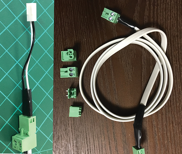
Figure 6-1: Short pigtails connecting mBot Motor pins to the common connector and long partner cables
The joy of Gary’s midpoint connectors comes from the unexpected ability to reuse parts. When a student wants to reuse a DC motor salvaged from an old toy, Gary’s system allows the kid to “make the cable” by adding the screw terminal plug and connect it to their mBot in a few minutes. These connectors eliminate an incredible amount of cable-related hassle in our Makerspace, and allow kids to push their mBots in surprising new directions.
For the small-scale projects in this chapter, you can connect the extra fans, motors, and pumps any way you like. But if you’re going to build two or three projects like this, take a lesson from Gary and invest the time in some midpoint connections.
Building Small
Although we use the word dollhouse throughout this chapter, we avoid that term in classroom settings, because it may seem childish to certain audiences. In our Makerspaces, we use a variety of figures to match the scale of some projects. When kids are building complete environments, we’ll look for 1–2″ figures, like LEGO mini figs or Playmobil figures. When designing clothing or furniture, 12″ poseable mannequins, bought for around $5 from IKEA, work wonderfully.

Figure 6-2: In class, we refer to anything we’re building for these mannequins or another anchor figure as a scale prototype. Image courtesy of Chris Willauer.
Working on a fixed scale means that kids can move from idea to sketch to prototype quickly, without losing a moment in a long hunt for materials. Iteration is fast and cheap when you’re making a parade float for 2″ figures or sewing a jacket for a 4″ torso.
For projects that create responsive environments, we’ve found that the best scale-human is the familiar LEGO mini fig. This way, an “apartment block” can be a vertical shoebox, single LEGO bricks can serve as furniture (see Figure 6-3), and clear tape becomes a useful building material.

Figure 6-3: A little LEGO work transforms a shoebox into a kitchen. Dishes in the sink are a nice touch.
Working in small scale lowers the cost (in time and materials) of “bad ideas,” and ensures that students can have plenty of chances to learn from those productive mistakes. Miniature scale reduces the importance of detailed and accurate plans, something students struggle with and rarely see the value of. Instead of allowing a long time for planning, students can start to build their first prototype after only making a quick sketch. To help build planning and sketching skills, we ask them to make a careful drawing of their finished prototype, and then refine that drawing for the next build. Two small steps, planning, then analysis, better mimics the Maker mindset, where the current work is always an approximation of the ideal.
Fire Management System—Small
With all of the aforementioned in mind, we’re going to use the mBot to construct a fire suppression system for our dollhouse. We call it that because, without a narrative context, a segment of silicon tubing pumping water through a cardboard box doesn’t mean anything. Twenty minutes of work, even shoddy work, can transform the same hardware into an apartment sprinkler system. We tap into every kid’s imagination and diverse crafting skills by framing the project as a sprinkler system, instead of an abstract challenge of moving water between tubs. Within that framework, even simple decoration for the shoebox apartment requires choices that refine the scale.
The constraint of this prototype is that it must extinguish a fire that occurs on the stove. This constraint encourages builders to narrowly focus their work on the functional part of the system. As a prototype, this isn’t better or worse than a “spray everywhere” sprinkler system, but adding that level of specificity allows students to leverage their real-world experience, so that each iteration of the cardboard prototype reflects and comments on that understanding.
Working with fire at any scale involves risk. In the small-scale shoebox apartment, even a single tealight could, if left unattended, result in a real and dangerous fire. In a classroom setting, you should limit the number of candles lit at any given moment. It’s far easier to keep track of four flames than 40. Lighting and then quickly dousing the candle is the capstone of this project, but there’s not much call for open flame before that moment. Along with the tealight, we’ll explain how to use a wide-band IR LED to test the pump system.
DC water pumps come in several varieties, but for this project we’ve had the most success with submersible pumps. Makeblock sells the pump shown on the left in Figure 6-4, which has a nominal 12V rating, just barely within the mCore’s power range. Unlike the submersible pump on the right, the DC motors and electrical connections on Makeblock’s pumps need to be kept dry.
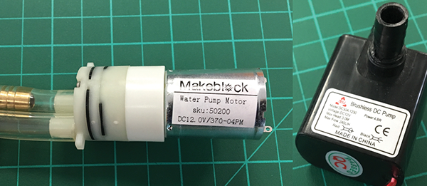
Figure 6-4: Makeblock’s 12V pump just barely works on mBot motor ports and needs to be kept dry. The black submersible pump is a better choice.
In addition to the power concerns, we find dry pumps tricky to use in a group setting. Keeping an appropriate distance between the microcontroller, the electrical connections on the pump, and the flowing water requires a lot of space for each setup.
It’s easier to find submersible pumps designed to work within the power range of the mCore’s 5V motor supply. Searching online for “USB water pumps” will help filter out the larger aquarium pumps, which are too large for this prototype stage. Small submersible pumps are quieter than the external dry pumps, and only require a single outflow hose. Best of all, the pumps and the electrical connections are designed to be wet! We often have kids build a self-contained reservoir for the pump to be used throughout the prototyping stage, and that’s what we’ll built next. The parts for the reservoir are shown in Figure 6-5.
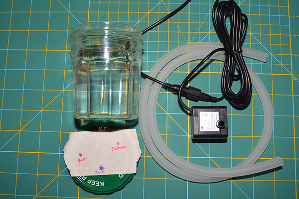
Figure 6-5: Here are the parts for the water reservoir. We’ll make three holes in the lid: two for the tube and one for the power cable.
This example uses a glass jelly jar, but wide-mouth plastic containers would work just as well. First, punch or drill three holes in the lid. Holes for the water to flow through are sized so the plastic tubing fits in them snugly (see Figure 6-6). The hole for the electrical connector has to be large enough to accommodate the plug.
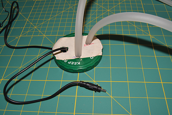
Figure 6-6: If the holes are too large, the tube may flop out of the lid when under pressure.
- Connect one of the plastic tubes to the outflow nozzle on the pump. The return tube doesn’t need to attach to anything (see Figure 6-7).
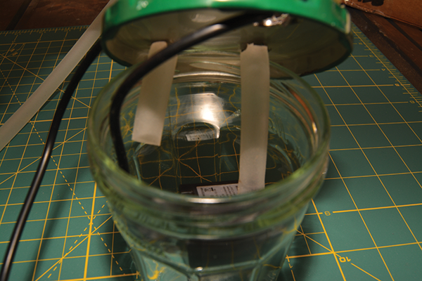
Figure 6-7: Connect one tube to the submersible pump’s outflow, and let the return tube dangle.
- Place the pump in the reservoir jar and pull out the slack on the power cable. If you’re using a metal lid, be careful not to slice open the tubing (bad) or power cable (worse!) on a sharp edge.
Now you can fill the jar when the pump is in use and screw the lid and connectors in place. This contraption isn’t spillproof, but it allows the pump and connectors to move around without soaking the work area. Blue tack or other moldable materials can seal the area where the tube travels through the lid. The completed reservoir is shown in Figure 6-8.
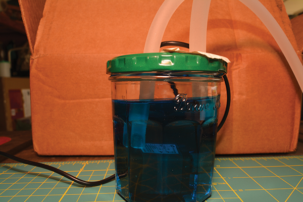
Figure 6-8: Here is the completed water reservoir with the tubes attached and the pump on the bottom. You can use food coloring to help you tell from a distance when the water is flowing.
With the pump and water source secured, we will turn our attention to the flame sensor. Like most Makeblock products, the functional heart of the Me Flame Sensor is an off-the-shelf component mounted onto a small board with an RJ25 plug. The following image shows the Me Flame Sensor with the telltale RJ25 plug below and a similar component with a header pin connection.
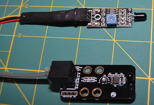
In general, what we call flame sensors are light sensors tuned to a particular wavelength of the infrared spectrum, normally between 760 and 1110 nanometers. Flame sensors actually combine an analog sensor, for numeric values, and a digital sensor that just reports whether there is fire or no fire. This digital reading also triggers a blue LED on the board and is controlled by a built-in threshold value, set by the small potentiometer (see Figure 6-9).
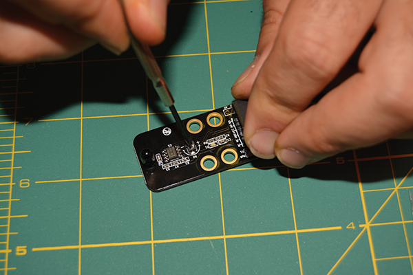
Figure 6-9: Adjust the Me Flame Sensor’s sensitivity by adjusting the potentiometer with a small screwdriver.
In our model, the sprinklers should only respond to an out-of-control kitchen fire. While an overzealous smoke alarm might be a kitchen annoyance, having a sprinkler set with too low a threshold makes a kitchen all but unusable. Managing the sensitivity of the flame sensor through physical placement and programming is the heart of this project.
There are some obvious concerns when kids are working with fire, but this project is a great way to mitigate those risks while enjoying the benefits. We use small tealights for the kitchen flames in these models, which provides more than enough fire to trigger the flame sensor. If placed too closely, it can also create enough heat to melt plastic tubing, crisp cardboard edges, or ignite stray paper scraps. Don’t leave an open flame unattended!
Anyone who moves a lit candle in and out of the model apartment risks wax-covered LEGO bricks and fingers. With regular attention, none of these problems threatens life or limb, and each one brings a useful “reality reminder” into the prototyping process. It’s also possible to avoid these candle-related mishaps by using an IR LED “throwie” to test the position of the flame sensor.
LED throwies are a staple of classroom Makerspaces. Just place a 3V CR2032 battery between the legs of an LED, apply a little tape, and you’ve got a small light to stick just about anywhere (see Figure 6-10).

Figure 6-10: The top two LEDs use colored plastic to narrow and focus the IR light. Wideband LEDs with clear tops (bottom two) are better for this project but either would work.
It may be the simplest circuit possible, but it delights and fascinates kids everywhere. But, since infrared light is outside the spectrum of human vision, it’s harder to know that the light is really on. Make sure to place the longer leg of the LED on the smooth positive side of the battery and the shorter leg on the dimpled negative side. For anyone new to LEDs, it’s helpful to do this with a visible-light LED at the same time (see Figure 6-11).

Figure 6-11: The wideband IR LED on the left is emitting as much light as the red light on the right.
Phone cameras used to provide a great way to check IR LEDs, since they capture a wider spectrum than the human eye. Today, the primary (rear-facing) camera on most phones uses software filters to clean up IR noise. Thankfully for us, that dubious feature hasn’t yet migrated to the front-facing camera!
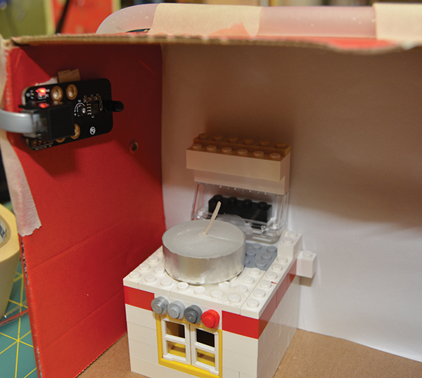
Since the flame sensor is actually an infrared sensor, these LEDs will easily impersonate a flame in a cardboard apartment. A large part of placing the flame sensor involves checking for ways the decoration and furniture might obstruct the sensor’s view of the stove. While this could mean simply moving the sensor, many students will choose to adjust the candle or the stove instead. This leads directly to wax-covered fingers and other candle-related injuries. Using an IR candle instead of an open flame for these steps drastically decreases the risk of this project (see Figure 6-12).
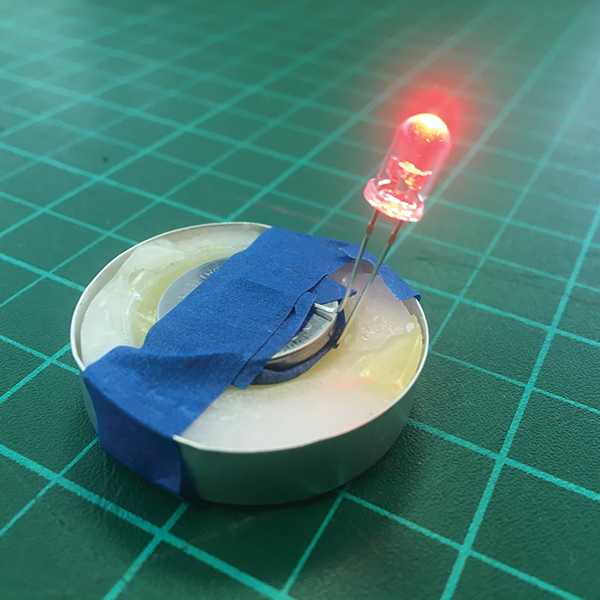
Figure 6-12: This image shows bends a visible light red LED throwie into a more convincing tealight shape.
With our test candle ready to go, it’s time to consider where to place the hose and sprinkler valve. This particular section of flexible tubing felt too large compared to the furniture, so we placed it on top of the cardboard box instead.
- Mark the position of the tube on the outside of the box.

- Place the tube so that it passes over the stove, then cut a small slit into the roof. It only needs to be large enough for water to drip through.
- Use tape to attach the tube to the box on either end of the opening.

Even with the threshold knob dialed down, the flame sensor will spot a flame in the small prototype apartment from any spot with an unobstructed view. As an additional challenge, consider trying to hide the bulk of the sensor outside the box and make an opening for just the IR sensor.
With the sensor placed, it’s time to build the code, shown in Figure 6-13. The flame sensor has both an analog numeric output and a digital on/off output. The mBlock only reports the analog numeric value from the flame sensor. Use a Say block to check the sensor values as you move a lit candle or match in and out of the scene. When the sensor can see a flame, the number drops significantly. On the Makeblock flame sensor and most others, there’s a small LED on the board that lights up when the sensor can see a flame. Keep an eye on this blue light while positioning the candle and adjusting the threshold knob to determine a useful threshold value.

Figure 6-13: This program has many elements in common with the traffic light classroom volume meter from Chapter 2, “mBot Software and Sensors.”
Our testing showed a flame sensor reading of 100 was well below the ambient light levels, but a bit above the direct fire readings. We used that for the FlameThreshold value at the top of the program so that it’s easy to change, if necessary.
To avoid soaking the kitchen every time there’s a momentary flare-up, this code includes a timing loop that checks how long there’s been a flame in the kitchen. A single big flambé moment shouldn’t trigger the sprinklers. The TimeToSprinkler variable is the number of seconds that we’ll wait before turning on the sprinkler.
This program uses custom blocks to turn the sprinkler on and off. Since this action only requires one command block, it isn’t saving any program length. Instead, it provides clarity in the main program, and flexibility if we change how the sprinkler connects to the mCore.
If the sensor reading is below our FlameThreshold value, the top part of the If/Else statement loops and resets the Scratch timer back to zero. However, once the sensor value clears the FlameThreshold value, the Else clause will execute and the timer will climb steadily. If the timer exceeds the TimeToSprinkler value, the pump turns on and will keep going until the FlameSensor value drops back below the FlameThreshold value.
We’ve used Sound and Say blocks to help track process throughout the program. When a program uses nested loops, it’s tricky to say exactly what’s being checked at a given instant. A drum sound plays every time the Else clause executes, providing an audio clue that the sensor is reporting a fire and that the timer is running. By adding a sound cue to the TurnSensorOn block, we can track any lag between the program’s signal to start the pump and when we see water flowing in the prototype.
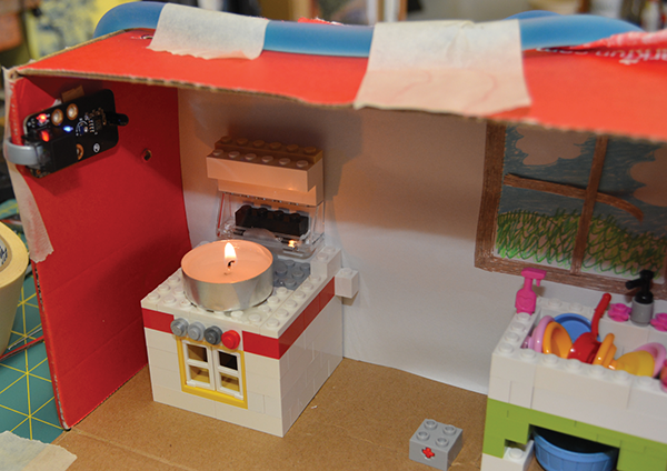
Figure 6-14: Here, we are testing the setup with a live flame and a sealed tube. Don’t abandon the tealight in the kitchen!
Now we’re ready to test the system. Before any water starts splashing, we’ll test the system as a closed loop (see Figure 6-14). Our pump will pull water from the reservoir, move it through the sprinkler system, and then back to the jar. This test is a useful practice for individuals, but crucial when working with groups. Ask that kids demonstrate a working closed loop system before they grab tools and poke holes in the tubing. Pierce the tube to add the actual sprinkler action when the code is solid.
This is the time to adjust the values for FlameThreshold and TimeToSprinkler. Our example uses about 1′ of tubing for the entire water path, so water reaches the kitchen less than a second after the pump turns on. For systems with longer hoses, such as one that has to reach a big bucket of water on the floor, it might be desirable to trigger the water a bit earlier.
Once those details are squared away, it’s time to install the actual sprinkler! Use a felt-tip pen and put a small mark on the hose where it passes over the stove. Lift up the tube and drain the water from it. Use a hobby knife, scissors, or a pair of pliers to take a small notch out of the tubing (see Figure 6-15). When the tube is filled, pressure will force water out of this gap, so a small opening will work fine. A small snip is also easier to patch up with hot glue and electrical tape.
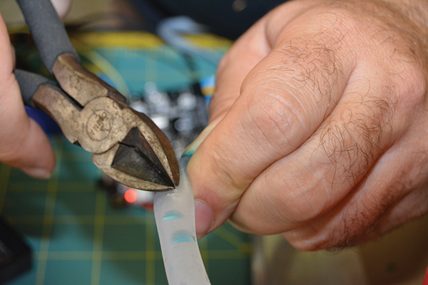
Figure 6-15: There’s no need to remove lots of plastic. Water pressure will force water out of a small opening.
Replace the end of the hose in the water reservoir. The bulk of the hose should now be empty, so it won’t drip into the apartment.
Here’s the moment of truth! Start the mBlock program, then place the lit tealight on top of the stove (see Figure 6-16).

Figure 6-16: Success! Water from the sprinkler system completely douses the runaway fire on our stove.
Even though this cardboard kitchen won’t last forever, we can make a few tweaks and test the system again before the box falls apart. Experiment with flame placement, with an eye out for spots outside of the splash zone that still trigger the sprinkler. Keep exploring ways to keep tiny apartment safe and intact.
Fan for Crowded Room—Small
The fire sensor demonstrates how a small-scale project with a reasonable narrative can support nuanced and complicated builds with very few components. It’s also the best way to introduce and foster interest in projects that combine data from multiple sensors. Small environments are easily to monitor and manipulate, making it possible to mimic the automation in everyday life.
This project models common HVAC systems that engage fans or AC when the temperature exceeds a threshold, but only when the rooms are occupied. Don’t forget to start with building the room—we can’t overemphasize the value of asking kids to create and invest in the design and decor of the environment (see Figure 6-17) before they start working with the electronics.

Figure 6-17: A few fairies and some LEGO furniture can go a long way toward anchoring creativity and enthusiasm.
Our years of classroom observations suggest that decorating the test environment before starting a project inspires students, while making a “pretty box” for a functioning prototype feels like busy work.
You can use the same temperature sensor as you used for the sensor bots in Chapter 4, “Measurement Devices.” This project serves as a natural follow-up to those data-gathering devices, and asks designers to use the power of observation to inform how and where to mount the thermometer. In a small-scale environment, sensors aren’t even close to invisible when taped to a wall. Raising the imagined concerns of the scale-model inhabitants is a powerful technique for prompting and encouraging deeper thinking.
Since all small fans are just DC motors with plastic fins, use whatever materials you have on hand (three types are shown in Figure 6-18). Dollar stores often have handheld fans that use 2 AA batteries, which work well hooked up to mCore’s motor ports. Makeblock sells an official version of this kind of fan, but it doesn’t use the same connector as the mCore. Small electronics often contain 3V or 5V square fans, which are easy to attach to flat surfaces with tape. The littleBits fan Bit is one of this type, but unless you’re already deeply invested in that product, it’s not worth spending $15 on a $2 fan.
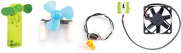
Figure 6-18: A handheld fan from the dollar store, Makeblock’s official fan (its connector is shown to its right), and the fan Bit from littleBits
Unfortunately, the most common recycled small square fans come out of desktop computers and run off 12V. These fans normally won’t move on the mCore’s 5V power supply. If you have a large supply of these on hand, it might be worth using some of the higher voltage power techniques from the “Building Big” section later in this chapter to bring those into the mCore universe.
Whatever fan you choose, it’s important to mount it in the scale room in a way that won’t obstruct tiny feet or sever tiny heads. We’ve used a square fan and mounted it in the “window,” as you can see in Figure 6-19.
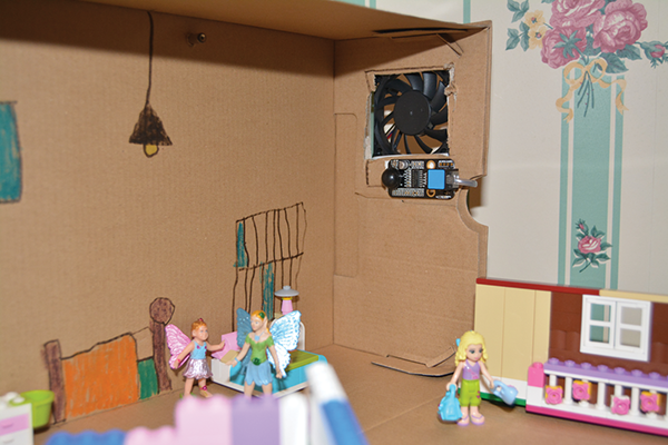
Figure 6-19: A crowded apartment with a PC fan installed and a thermometer high on the adjacent wall
At this point, we can write a simple program to turn on the fan when the temperature climbs past a threshold (see Figure 6-20). Even though turning the fan on only takes a single block, it’s worth defining those commands in custom blocks.
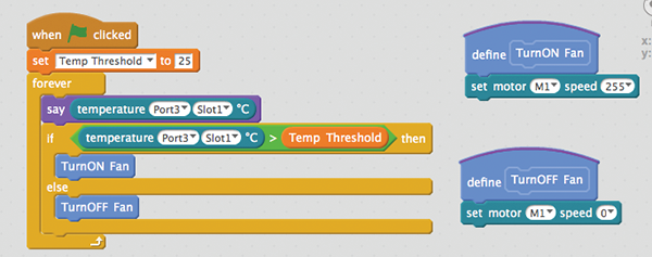
Figure 6-20: This is the State Check code from the sensor projects in Chapter 2.
It may require applying cold or hot fingers to move the temperature quickly above and below the threshold. Don’t let the giant hands reaching in and out of the room break the narrative illusion completely! Look for ways this simple feedback loop would delight or annoy the tiny people relaxing on the couch.
With these barebones environmental controls in place, it’s time to consider how to determine if the room is occupied. Similar to the way we determined whether a door was standing open in Chapter 4, there’s no single “correct” sensor that will help us answer this question. Determining how to use an arbitrary input to decide whether people are in a room is a great brainstorming activity, if not an entire project. Pull a random sensor out of a hat and see what you can improvise!
This example uses the passive infrared (PIR) motion sensor, not because it’s best, but as a way to showcase the particular challenges associated with binary output. A PIR sensor uses pyroelectric materials that actually generate electricity when exposed to specific wavelengths of light. Unlike the flame sensor, the PIR doesn’t report a value relating to infrared light levels, but responds when that light value changes significantly.
In mBlock, the angled frame of the PIR block indicates that the sensor’s values will always be either 0 or 1. When the PIR motion sensor block reports 0, that indicates that infrared levels have been basically stable for the last few milliseconds, which we interpret to mean that nothing large or warm is moving nearby. If the infrared level changes in that small window of time, the sensor reports a 1. The basic shorthand of 0 = still, 1 = movement, works for most situations, but it’s worth considering the edge cases. A flickering candle will confuse a PIR sensor and it will report motion, whereas snakes and other cold-blooded reptiles could sneak by undetected—shudder. That is yet another reason to be afraid of snakes.
Most people already have an intimate familiarity with PIR-related frustration from countless restrooms. From finding the right position of your hand for automatic sinks, to stingy paper towel dispensers, many public bathrooms are crowded with PIR sensors. One strength of this project is that it can put kids in control of the same kind of robotic systems they encounter every day. As a general principle, humans should be able to build something as sophisticated as their own bathroom fixtures.
Since the PIR is a binary sensor, our program should look for readings over time rather than a single reported sensor value. The amount we’ll accept as “enough” motion in a short time interval becomes our timing threshold. The fan should wait for the value to fluctuate frequently as an indication that people are actually moving in the room. This is essentially the same calculation performed by the sensor itself, but on the scale of seconds, not milliseconds. Since we’re using the PIR data to turn on a big, slow fan, checking for several signs of motion over several seconds will ensure the fan doesn’t turn on and off constantly.
Once we’ve seen that period of consistent movement, we need to mark the room as occupied and stop checking as frequently. Again, as in a bathroom, we accept that people will move around when they arrive in a room and sometimes sit for a while. Our code needs to allow the imaginary little people to relax on the couch for a reasonable amount of time without having to wave their tiny arms.
It’s essential that we check and tune the three discrete subsections shown in Figure 6-21 in isolation before combining them into a larger program. When debugging a complicated system, all the individual components must perform consistently. Test how much motion it takes to trigger the PIR sensor. Run a Say loop with the temperature sensor and ensure that the fan actually lowers the room temperature. Test all the likely scenarios, and as many strange ones as you can imagine.
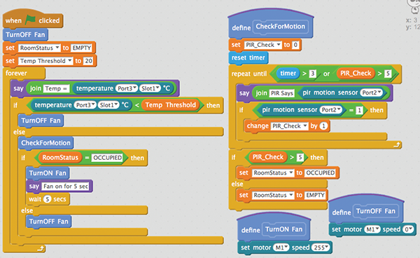
Figure 6-21: Once they are all combined into a single stack of blocks, it’s trickier to find and correct errors.
Only when the fan, PIR sensor, and temperature sensor behave well in all those tests can we check all three together. When a program evaluates and compares many different inputs, the order and timing of how we check those inputs matters!
As the complexity of mBlock programs increases, it’s important to remember that the goal is functionality, not correctness. Rather than worrying about whether a particular solution represents the “right way,” keep focused on if it accomplishes your stated goals. Robots and programs are tested, not graded.
Testing throughout the build process not only compartmentalizes large tasks, but the tests force us to consider the question, “What should happen here?” on increasingly granular levels. That mindset helps even when you’re reading unfamiliar programs for the first time—something Makerspace and computer science teachers do on a daily basis. Working through a small part first, and thinking through what should happen at each step, can be very helpful.
We pulled CheckForMotion out as a custom block to isolate the choices made in that process. CheckForMotion looks at the data from the PIR sensor for three seconds or until it sees five motion readings, whichever comes first. The PR_Check value starts at 0 each time CheckForMotion runs, and then increases each time the PIR sensor reports a 1. At the end of CheckForMotion, the RoomStats variable is reset to either Empty or Occupied.
Reading the details of a program should suggest ways for you to extend its functionality or even ways to reshape it around different assumptions. Maybe it’s time to add a thermostat sized for tiny LEGO hands rather than use a fixed temperature threshold. Instead of bouncing between off and full power, maybe the distance between the current and ideal temperatures should determine the fan’s intensity. Gary Stager names this improv-like questioning process “...and then?” and suggests that it’s a useful filter for finding the unexpected corners of complicated tasks. Static adult-centered tasks rarely generate great “…and then?” responses. On the other hand, one or two “…and then?” questions asked of different groups of young people could push this basic project in radically different and fascinating directions. Great projects can generate enough interesting responses to “…and then?” to fill up a whiteboard.
Building Big
As we’ve seen in previous chapters, the mBot system allows us to create on a very large scale. Using serial or Bluetooth for wireless communication means that the mCore board or mBot robot can operate far away from the computer or tablet. Uploading the programs to the board, along with the use of a large LiPo battery, allows our creations to operate independently for hours or days at a time. Cheap custom cables make it possible for sensors and motors to spread out along the ceiling or windows of even the largest rooms. In many ways, we’ve already been “building big” with the mBot.
Now it’s time to cross the final threshold of “big” and work with large power loads.
In the section “Connecting Motors with Two Wires (Two-Pole Motors),” we demonstrated how to connect any simple DC motor to the mCore’s motor output pins, allowing us to control fans, pumps, and more. All of those devices were pretty small, and easily powered by the mCore’s 5V low-amperage output. This works great for prototypes, where exploring and refining the idea is more important than doing real work. But if we want to soak a real kitchen, we’ll need to control devices that require far more power.
Controlling large loads with small voltage signals is a central pillar of the Arduino universe. All microcontrollers operate on either 3.3V or 5V electricity. Powering a device through a microcontroller requires all the power used by that device to flow through the same circuit. Controlling larger voltages will require an extra component to switch on the bigger power stream in response to signals from the microcontroller.
There’s a whole world of options that will allow you to control exactly the device you want with a given input, and there’s no better book to start with than Charles Platt’s now classic Make: Electronics: Learning Through Discovery, Second Edition (Maker Media, 2015). His hands-on walk-through of physical and solid-state relays and transistors is an essential experience for all Makers.
In our classrooms, we choose parts that are often overkill for the specific applications. When selecting relays or transistors, we stock a few parts that can control a wide range of voltages, rather than finding the switching circuit that’s just big enough to handle a specific task. While there’s surely a more efficient and possibly cheaper solution for the systems shown in this chapter, that’s not our primary concern. Because we allow young people creative autonomy, I’d rather have a dependable and flexible tool ready at hand than go digging through a drawer of parts.
Fire Management System—Large
If you harbored safety concerns when kids were using a candle in a cardboard kitchen, the idea of taking that project to life-size may be downright terrifying. There are plenty of great, safe, empowering ways to teach young people how to build and control fire, but all those lessons are better suited to a camping trip rather than a Makerspace.
Instead of scaling up the fire, we’ll focus on scaling up the response. We’re going to leave the small pump behind and build a garden hose–powered sprinkler.
Water is heavy, and moving a lot of water requires a corresponding amount of power. That’s why most real-world sprinkler systems don’t use electric motors to push the water. Fire safety systems rely on water pressure and use valves that degrade and open in extreme heat. Gardening valves, which start and stop the flow of water with solenoid-driven plugs, provide a better model for our project.
In this project, we’ll build a water control system that opens a solenoid valve using 12V DC power. Since that much voltage would fry our poor little mCore, we’ll need to use an external 12V power supply, and a physical relay. Signals from the mCore will tell the relay to close or open the larger electric circuit that, in turn, controls the valve.
For big DC projects that don’t require millisecond-speed switching, I reach for SparkFun’s Beefcake Relay board, shown in Figure 6-22.

Figure 6-22: SparkFun’s Beefcake Relay board
This board can switch up to a 3A load at 28V DC. The actual relay could handle up to 20A, but the screw terminals and traces on the board aren’t rated for huge current loads. The Beefcake can also switch 220V AC loads, meaning that it could handle wall current from most countries, but we don’t use the Beefcake for that. Even with the precautions we take in our Makerspaces, having wall current move through a board with exposed terminals and traces gives me the willies. When we need to control something that plugs into a wall outlet, we reach for the PowerSwitch Tail, which we’ll use in the room-scale fan project later in this chapter.
Figure 6-23 shows the relay used in the Beefcake relay board with the black plastic housing removed. Don’t do this! The plastic cowling prevents fingers from coming into contact with high voltage. Relays use a large copper coil as an electromagnet. When a low-voltage current flows through the electromagnet, the electromagnet pulls a switch closed, which will physically complete a high-voltage circuit. When the current stops flowing through the electromagnet, the switch is released, and the high-voltage circuit is broken.
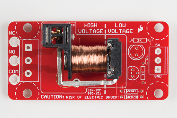
Figure 6-23: The coil is at the heart of the Beefcake relay. Image courtesy of SparkFun (https://learn.sparkfun.com/tutorials/beefcake-relay-control-hookup-guide). Image is CC BY-SA (https://creativecommons.org/licenses/by-sa/4.0/).
We’ll control this coil with a signal from the mCore to the side labeled Low Voltage. We’ll be using this relay to turn something on, which means we’ll use the normally open (NO) pins on the high-voltage side. Normally closed (NC) operation means that the circuit is closed by default and the device is powered, except when the microcontroller sends a signal. In our sprinkler setup, an NC relay would be a particularly wet and unpleasant way to fight household fires.
I was first introduced to the Maker utility of sprinkler valves by Joey Hudy’s classic marshmallow cannon project (https://makezine.com/projects/extreme-marshmallow-cannon/). Garden use valves consist of a connector between two pipes with a solenoid-controlled gate in between. Most are NC, meaning that the plunger blocks the flow between the two sides and requires current to open. Automatic garden-sprinkler solenoids are designed to use 24V alternating current (AC), but can operate for short periods with 12–18V DC power. The trade-off when using DC power is that it draws a higher current and generates extra heat while the solenoid is powered and the valve is open. This can cause problems when the whole package is buried beneath the lawn and stands open for half an hour at a time, but won’t pose a problem when open only briefly, as it is in this project.
While sprinkler parts from Home Depot or salvaged from the shed will work fine for this project, we will use a 12V DC solenoid valve from SparkFun. Since it’s built for light-duty applications like this, it’s a bit cheaper than parts from the garden department. It also has a reasonably square bottom and sits nicely on a bench. Gardening valves are designed to be buried in dirt, not sit flat on a work surface.
We’ll use the relay to control power to the solenoid valve. (See Figure 6-24.) Only when the relay is engaged and the circuit is closed will power flow from the supply into the valve, which will, in turn, open the valve to allow water to flow.
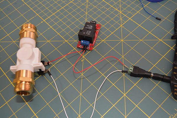
Figure 6-24: The power circuit between the 12V source, the sprinkler valve, and the Beefcake relay board
Figure 6-25 is what would pass for a planning sketch of the sprinkler control circuit in our Makerspaces. When you’re working with new tools and materials, abstracted circuit drawings can pose real challenges. Although the power plug isn’t connected to anything and the tiny wires aren’t soldered to the valve, this model is more similar to building the actual circuit than a drawing would be. Modeling with real parts also makes it easier for a teacher to quickly offer feedback.
However, this version is just a model. The “production” build needs some larger, longer wires. Thicker wires are better for higher current loads, and we need plenty of distance between our replay board, the flowing sprinkler head, and the microcontroller.
To keep this type of build flexible, it’s a good idea to build small, modular cable connections, as seen in Figure 6-25, discussed at the beginning of this chapter. In this project, we used barrel plugs backed by screw terminals. These plugs are familiar to kid hands and stand up to a lot of stress.

Figure 6-25: Similar to Gary’s midpoint connectors, but with heavy-gauge wires for high-current applications like a solenoid
Although longer wires help, the relay board needs a bit more protection. In group or classroom environments, we often package the relay boards in disposable plastic food containers, with small openings to allow access to the low- and high-voltage connections (see Figure 6-26).

Figure 6-26: The power input and the control wires emerge through small cuts in the plastic tub.
This isn’t waterproof, but it is splash-resistant. It also presents clear physical instructions to novice users—to control this relay, the only parts that are required are the wires sticking out of the side.
Now we’re ready to revisit our fire sprinkler code and modify it for the new parts. At dollhouse scale, the mCore provided power directly to the water pump through the motor ports. Since the relay board requires minimal current, we’ll use one of the RJ25 ports to send the control signal instead.
All of the blocks in the mBot section of mBlock are built around a specific sensor or actuator. Accessing more generic commands, like setting a single output to High or Low, requires the Arduino extension. Make sure the Arduino option is selected in the Extension menu, as shown in Figure 6-27.
Then find the Set Digital Pin Output As block in the Arduino section of the Robots palette. (See Figure 6-28.)

Figure 6-27: Small check marks in the Extensions menu indicate which blocks appear in the Robots palette.
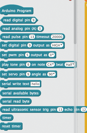
Figure 6-28: Programs in mCore can use blocks from the mBot and Arduino extensions simultaneously.
Every RJ25 port on the mCore has wires for two Arduino pins. When you’re using the RJ25 breakout board, those two pins are separated into the two 3-wire connection points. To determine which pin number to use in an mBlock program, plug the RJ25 breakout board into a port on the mCore, and then look at the labels behind the mCore connector. (See Figure 6-29.)
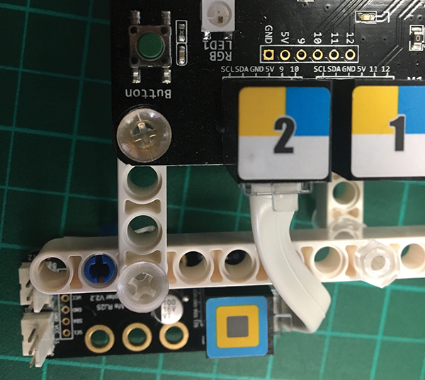
Figure 6-29: Pin names are listed behind each mCore port. When the RJ25 board is connected to port 2, slot 1 connects to pin 9 and slot 2 connects to pin 10.
In this code we used pin 9, which comes from port 2 of the mCore, and slot 1 on the RJ25 breakout board. Since any of the mCore pins would work for this example, why don’t we just use the default values? This means that the signal wire that’s connected to the Beefcake relay board traces back to pin 9 on the Arduino, running through port 2 on the mCore to slot 1 on the RJ25 board.
There are a few other alterations to make. The Set Digital Pin blocks call replaces the Set Motor blocks in the SprinklerON and SprinklerOFF procedures. Set Digital Pin 9 Output As High replaces Set M1 to 255 in SprinklerON, and Set Digital Output as Low replaces Set M1 to 0 in SprinklerOff. We also removed the Eat sound effect, because it’s just hard to hear the computer speaker when you’re testing outside. (You can see these changes in the following image.)

Now we can use this simple code to check the program and wiring of our circuit. The SparkFun Beefcake relay board features a small LED that indicates when the high-voltage side of the relay is engaged. Physical relays also make a distinct and pleasant clicking sound as they open and close. These small visual and audio cues are useful when testing your relay setup. Test your wiring and relay setup before attaching the hoses.
How you position the sprinkler, hoses, and wires depends more on the space getting soaked than the hardware that’s used. Pay attention to the threading on the valve and any hoses or connectors. Even when the connectors are the same size, pipe threading requires an adapter for normal garden hoses. Appropriate parts are available at most hardware stores.
Figure 6-30 shows the full setup with the plumbing equipment and the electronics connected, placed artificially close in order to fit in the image. Do not put your electronics this close to the hose and valve. When we ran preliminary tests, the exposed mCore sat far away from the water and under a towel.
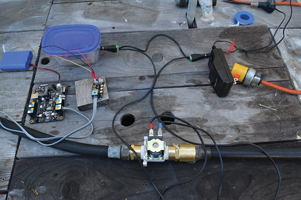
Figure 6-30: Here’s the mCore and battery, connected to an RJ25 board, which is connected to the Beefcake relay board, which is housed inside a waterproof tub.
Put a bit more space between the components and let the test program run. Look for lag time between when the relay triggers and the water flow stops or starts. Once you’ve chosen a time interval for the sprinkler that generates enough splash without overloading the relay, it’s time to mount the fire sensor and update the dollhouse sprinkler program.
Where and how you mount the fire sensor is entirely dependent on the sprinkler setup and how you plan to test. However, it’s crucial that the flame sensor stays dry! Not only would a wet sensor produce unpredictable readings, the flame sensor circuit is part of the mCore. Stray drops of water might short circuit the mCore and, in the best scenario, trip the fuse and depower the board. Adding a layer of cling film over the sensor is a great safety measure—it isn’t waterproof, but it does serve as a reasonable barrier against a few errant drops.
Once the flame sensor is mounted, make sure to test the reading. A frustrated kid jumping around with a lit candle trying to trigger the sprinkler increases the risk of this project significantly. Thanks to the wide angle of the sensor, the example setup will detect a flame in a large arc anywhere between 3′ and 8′ off the ground.
Now, gather your volunteers, and get ready to test! Figures 6-31 and 6-32 shows before and after.
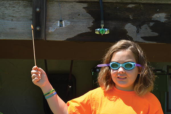
Figure 6-31: Wait for it…

Figure 6-32: It works!
Although this sprinkler setup emerged out of the dollhouse fire alarm, it doesn’t have to end there. You now have the ability to program arbitrary reasons to soak people! Maybe that traffic light classroom volume monitor was too passive. Soak the loud ones! Maybe balloon jousting should end by drenching the losing team. The possibilities are endless . . . and soggy.
Fan for Crowded Room—Large
After that mess of relays and hoses, it seems like scaling up the PIR temperature fan project should be much easier. The PIR sensor has a huge field of view and can easily cover most of a room. Discretely hiding a thermometer is easier at human scale than in a cardboard box. It seems like scaling up this project is just a matter of adding longer cables—until we get to the fan.
Even 120 mm computer fans don’t move enough air to affect the average human-scale room. However, box, desk, and oscillating room fans are powered by AC motors, rather than DC. These motors plug directly into local wall current (110V in the United States) to spin big blades and move a bunch of air.
Wall current is super dangerous—deadly, even! As a rule, our Makerspace does not work with mains electricity, aka, what comes out of the wall socket. Not only does it have the potential to fry people, it would obliterate all of the robots or motors we’ve seen thus far. Wall current is not your friend!
Room-sized fans need wall current. Although big relays, like the SparkFun Beefcake used in the sprinkler project, can switch 110V AC, we don’t use them with kids. Exposed traces and screw terminals present only a mild risk of accidental shock, but that’s more than we’re willing to accept when we have a classroom of adolescents.
Instead, we turn to the PowerSwitch Tail, shown in Figure 6-33, which encases a high-current relay inside a traditional power brick.
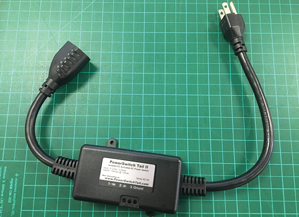
Figure 6-33: This PowerSwitch Tail is designed for use with US 110V wall current. There’s another version with appropriate plugs for countries using 220V standards.
The input wires on the PowerSwitch are fully isolated from the relay and the wall voltage circuit. Although I can’t say that this eliminates my nervousness at having young kids working with wall current, it’s enough to get the project moving. For budget-conscious electrical experts, there are much cheaper ways to use the mCore to control large fans, toasters, or hair dryers, but I sleep much better spending the extra cash on these.
The PowerSwitch Tail connects to the mCore like other relays, using the RJ25 expansion board. Since the low-voltage side of the PowerSwitch Tail is opto-isolated, meaning there is no physical connection between the high-power and low-power circuits. Instead, the bridge between the two circuits is a tiny LED and light sensor, not unlike the onboard sensor on the mCore. Because of this setup, you only need to connect the signal and ground wires from the RJ25 board, not the 5V wire. Connect the signal wire to the + Input pin, connect the ground wire to the – Input pin, and leave the ground pin on the PowerSwitch Tail empty, as shown in Figure 6-34.
As with the Beefcake, we’ll need to use the Digital Pin block from the Arduino extension to switch one particular pin to High or Low. A signal LED on the PowerSwitch Tail shows when the relay is engaged. Instead of having to hack apart a cable, the PowerSwitch Tail sits neatly inline between the room fan and the wall outlet, and the mCore can now control any household lamp or fan.

Figure 6-34: Unlike the Beefcake relay, the PowerSwitch Tail only needs the signal and ground wires connected. Cover the loose 5V wire from the RJ25 board.
With the PowerSwitch installed, the biggest challenge is replicating the physical setup of the dollhouse room at full scale. This is absolutely the time for super-long extension cables. Just like in the scale model, it’s important to test as you go to ensure that the airflow lowers the temperature on the thermometer. Also, the timers for the PIR sensor and the fan will need to be significantly longer. The real world is big, and it takes time for stuff to move around!
These projects represent one way you can extend mBot’s capabilities far beyond what arrives in the retail kit—but it’s not the only one. The mBot arrived into our elementary and middle school classrooms as an accessible, low-floor, programming and robotics platform. What’s kept them in use throughout middle and into high school is that the full power of the Arduino platform is just under the surface. Almost any Arduino project found in an issue of Make: will work with an mCore at the heart.