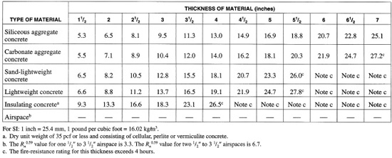

APPENDIX FIGURE 1 Values of Rn0.59.
APPENDIX FIGURE 2 Ceramic fiber joint protection.
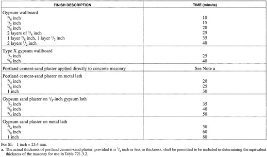
APPENDIX FIGURE 3 Time assigned to finish materials on fire-exposed side of wall.
APPENDIX FIGURE 4 Slabs with ribbed or undulating soffits.
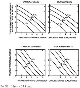
APPENDIX FIGURE 5 Fire-resistance ratings for two-course concrete floors.
APPENDIX FIGURE 6 Fire-resistance ratings for concrete roof assemblies.
APPENDIX FIGURE 7 Fire-resistance ratings for concrete roof assemblies.
APPENDIX FIGURE 8 Cover thickness for reinforced concrete floor or roof slabs (inches).
APPENDIX FIGURE 9 Cover thickness for prestressed concrete floor or roof slabs (inches).
APPENDIX FIGURE 10 Minimum cover for main reinforcing bars of reinforced concrete beams (applicable to all types of structural concrete).
APPENDIX FIGURE 11 Minimum cover for prestressed concrete beams 8 inches or greater in width.
APPENDIX FIGURE 12 Minimum cover for prestressed concrete beams of all widths.
APPENDIX FIGURE 13 Fire-resistance periods of clay masonry walls.
APPENDIX FIGURE 14 Fire-resistance ratings for bearing steel frame brick veneer walls or partitions.
APPENDIX FIGURE 15 Determination of the heated perimeter of structural steel columns.
APPENDIX FIGURE 16 Gypsum wallboard protected structural steel columns with sheet steel column covers.
APPENDIX FIGURE 17 Gypsum wallboard protected structural steel columns with steel studs/screw attachment system.
APPENDIX FIGURE 18 Fire resistance of structural steel columns protected with various thicknesses of type x gypsum wallboard.
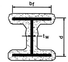
APPENDIX FIGURE 19 Wide flange structural steel columns with sprayed fire-resistant materials.
APPENDIX FIGURE 20 Concrete protected structural steel columns.
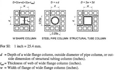
APPENDIX FIGURE 21 Concrete or clay masonry protected structural steel columns.
APPENDIX FIGURE 22 Determination of the heated perimeter of structural steel beams and grinder.
APPENDIX FIGURE 23 W/D ratios for steel columns.
APPENDIX FIGURE 24 Properties of concrete.
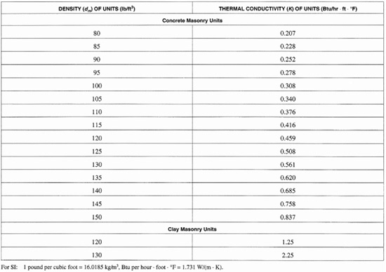
APPENDIX FIGURE 25 Thermal conductivity of concrete or clay masonry units.
APPENDIX FIGURE 26 Fire resistance of clay masonry protected steel columns.
APPENDIX FIGURE 27 Weight-to-heated-perimeter ratios (W/D) for typical wide flange beam and girder shapes.
APPENDIX FIGURE 28 Fire resistance of clay masonry protected steel columns.
APPENDIX FIGURE 29 Minimum cover (inch) for steel columns encased in normal-weight concrete.
APPENDIX FIGURE 30 Minimum cover (inch) for steel columns encased in normal-weight concrete.