Illustrations

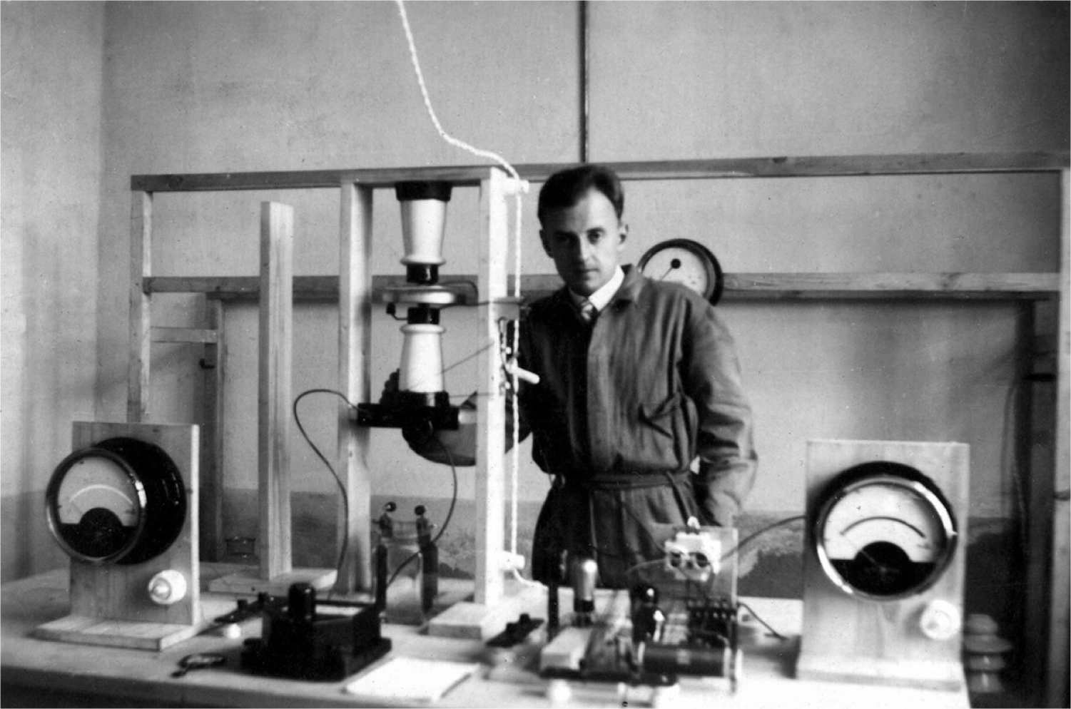
Chapter 1. Young Ronald Richter in his research laboratory before the war with his plasma-arc setup arranged on a bench. The equipment configuration looks neat and orderly.
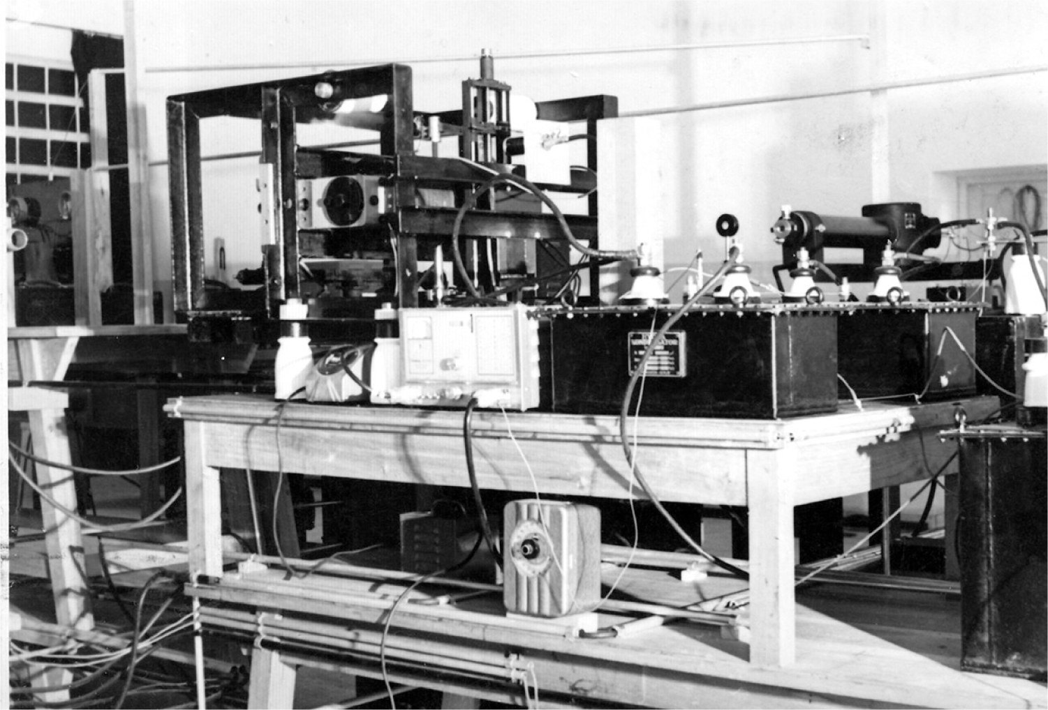
Chapter 1. Richter’s experimental setup in a corner of Kurt Tank’s jet fighter factory in Cordoba. The work-space appears cramped and loosely organized.
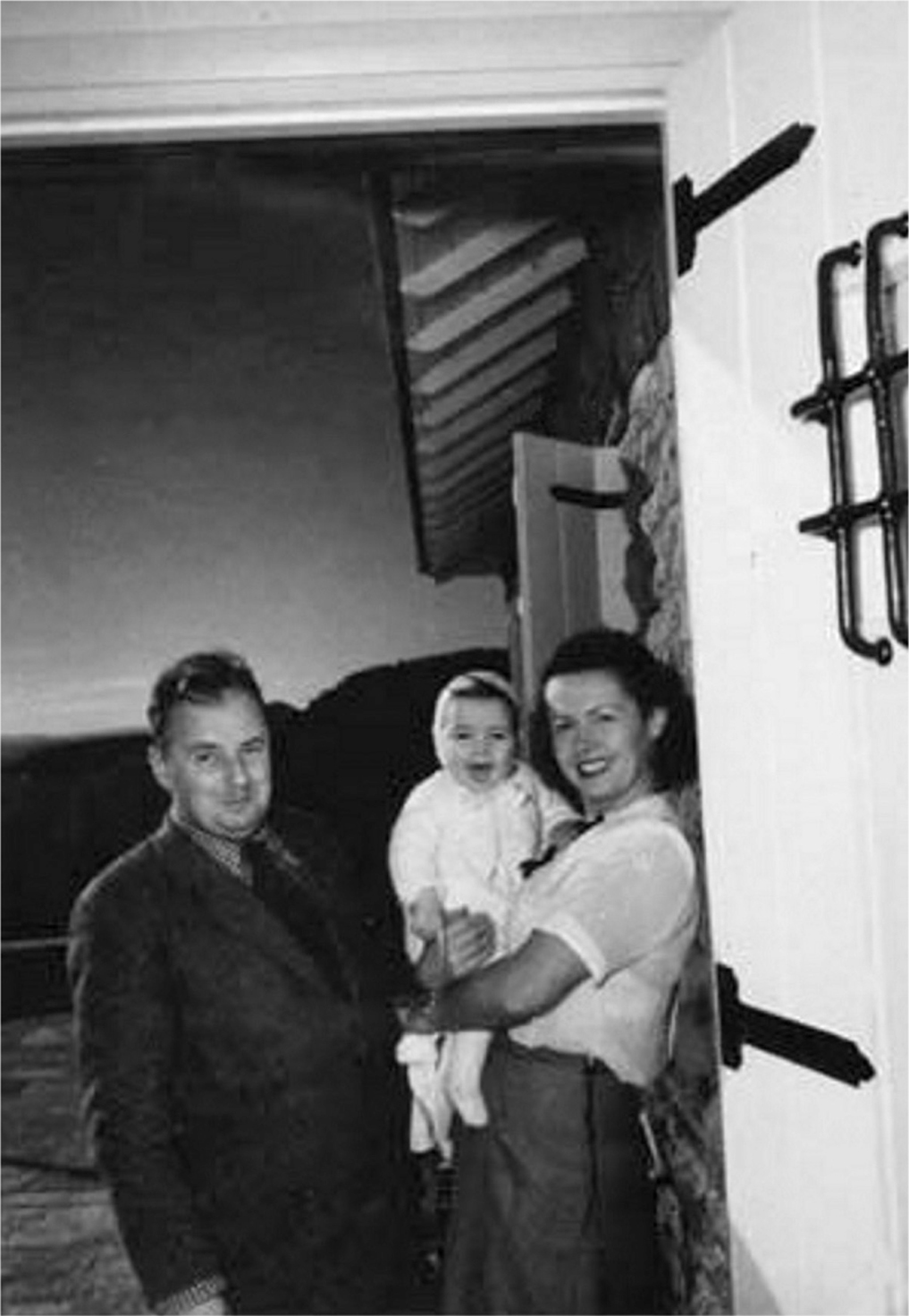
Chapter 1. Dr. Richter with his wife, Ilse, and his daughter, Monica, in their new home in Bariloche.
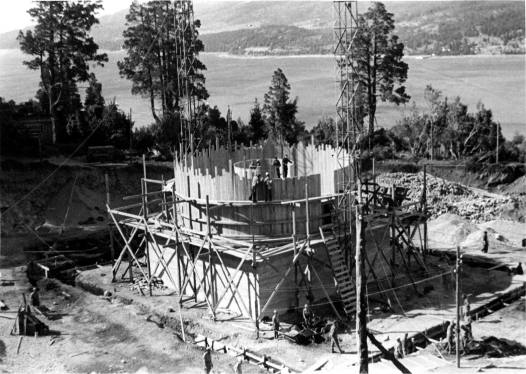
Chapter 1. The small fusion reactor under construction. Immediately after construction was finished, Richter had it torn down. This strange action affected his relations with the construction organization and with the military.
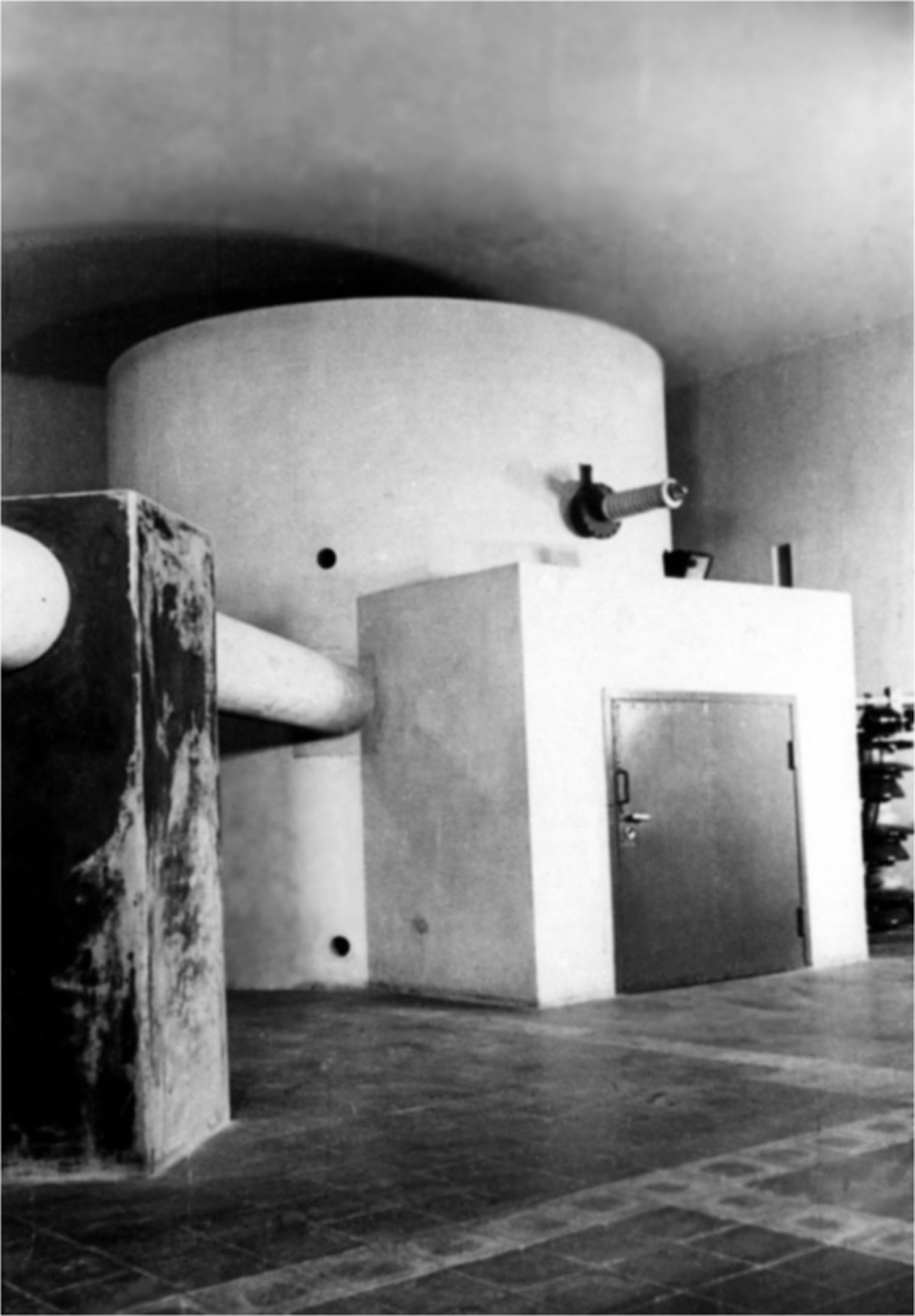
Chapter 1. The first fusion reactor constructed in Richter’s large laboratory building.
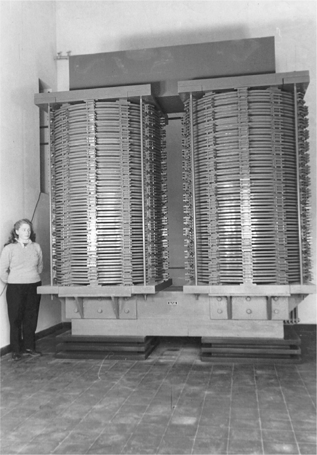
Richter’s 47-ton electromagnet. That may be his wife, Ilse, standing next to it.

Chapter 1. Richter at the control desk of his final fusion setup. To his right are two very expensive Tektronix oscilloscopes, and in front is an array of pen-chart recorders.
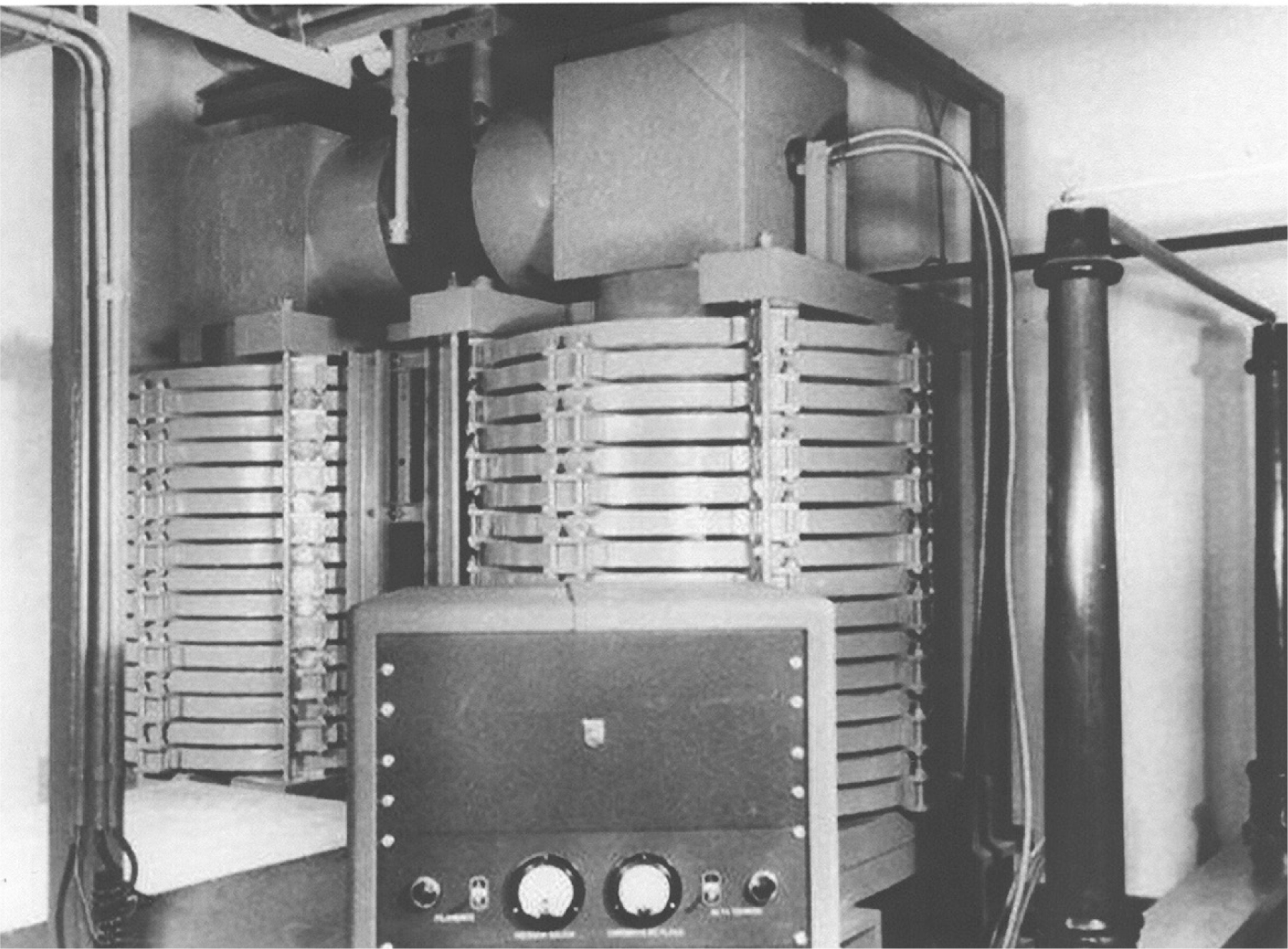
Chapter 1. Two lesser magnets forming a gap and a set of inexplicable high-voltage stand-offs at the fusion experiment. The reason for the extremely tall porcelain insulators is unknown, but there is speculation that Richter simply found them beautiful.
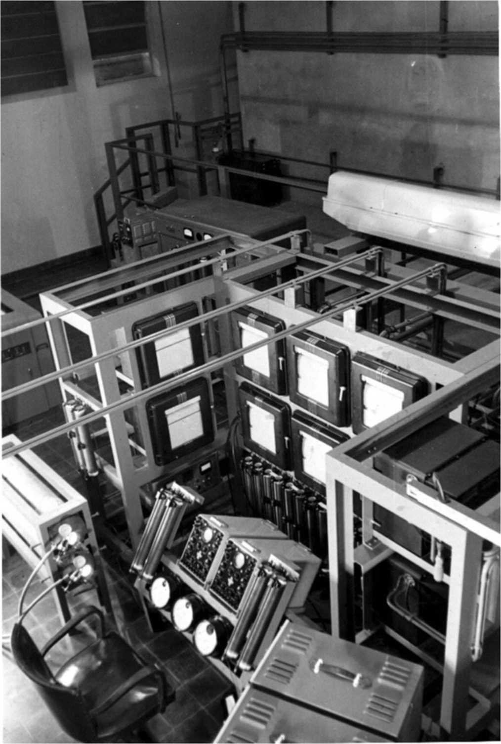
Chapter 1. This is another angle of the control desk, showing two Speedomax X-Y plotters in the top left corner. To the left of Richter’s chair are two pressure cylinders, probably filled with hydrogen gas. The setup is crowded but impressive for the amount of instrumentation. The oscilloscopes, at least, are not connected to anything.

Chapter 1. Behind the control desk and a concrete shield is the spark control circuitry. The big glass tubes on the left are kenotron high-voltage switching-diodes. The setup looks neat and orderly.
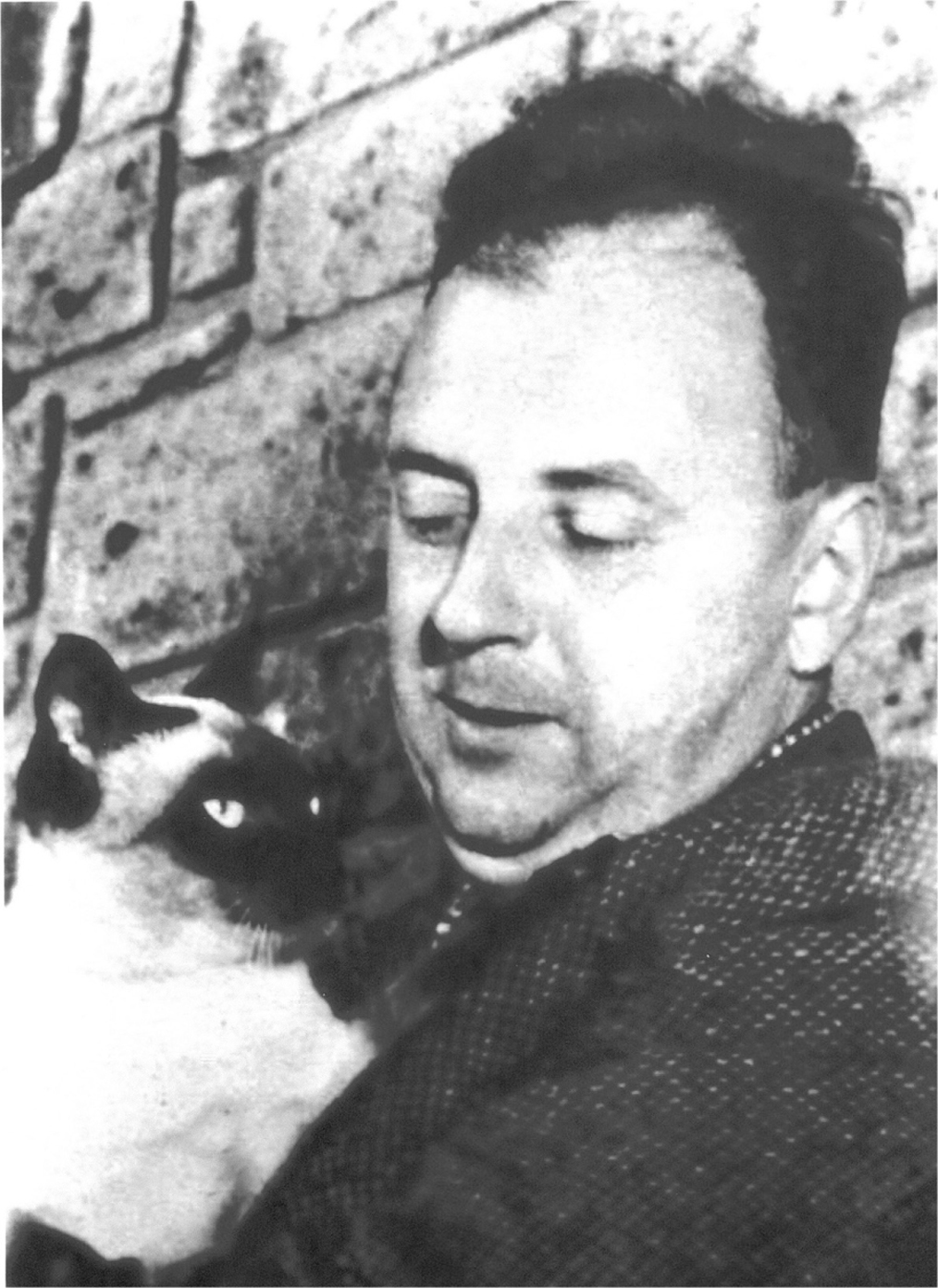
Chapter 1. Richter and his beloved cat, Epsilon, taken on July 12, 1955 at 5:00 in the afternoon. Two months later his patron, Juan Perón, would be ousted by a military coup.
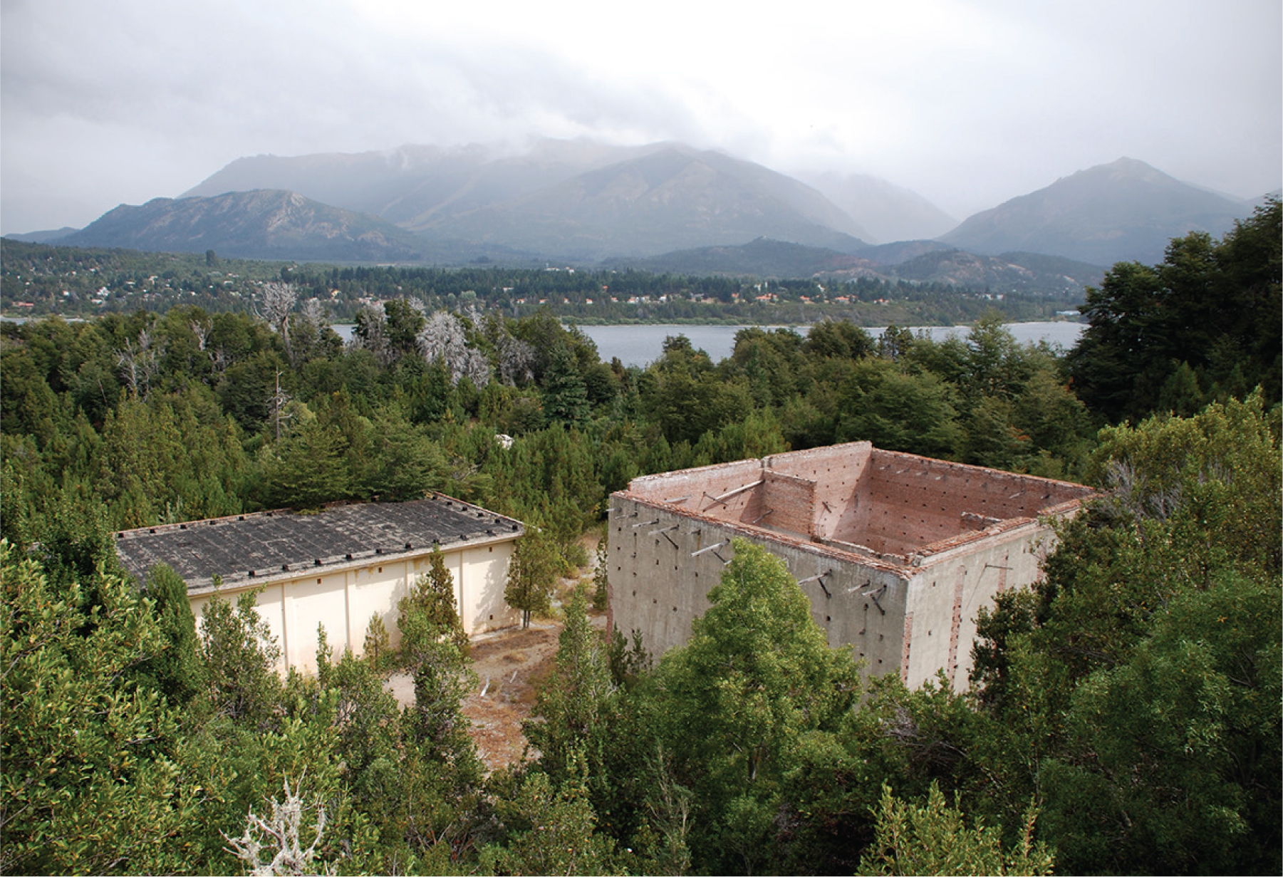
Chapter 1. Two of Richter’s laboratory buildings as they now appear.

Chapter 1. Visitors would stand behind the railing to be dazzled by one of Dr. Richter’s demonstrations.

Chapter 2. The main reactor at the REF being installed. Notice the very shiny stainless-steel walls.

Chapter 2. Mel Dewar touching something in the CEF (Critical Experiment Facility) reactor with a 10-foot pole.
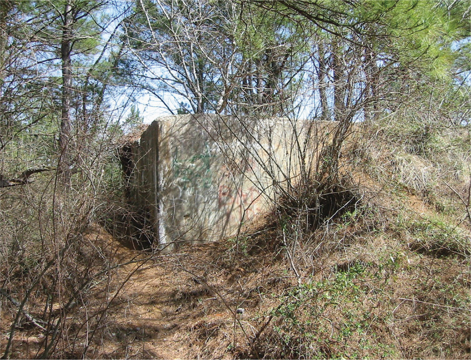
Chapter 2. The ground-level portal to the underground control room as it now appears.
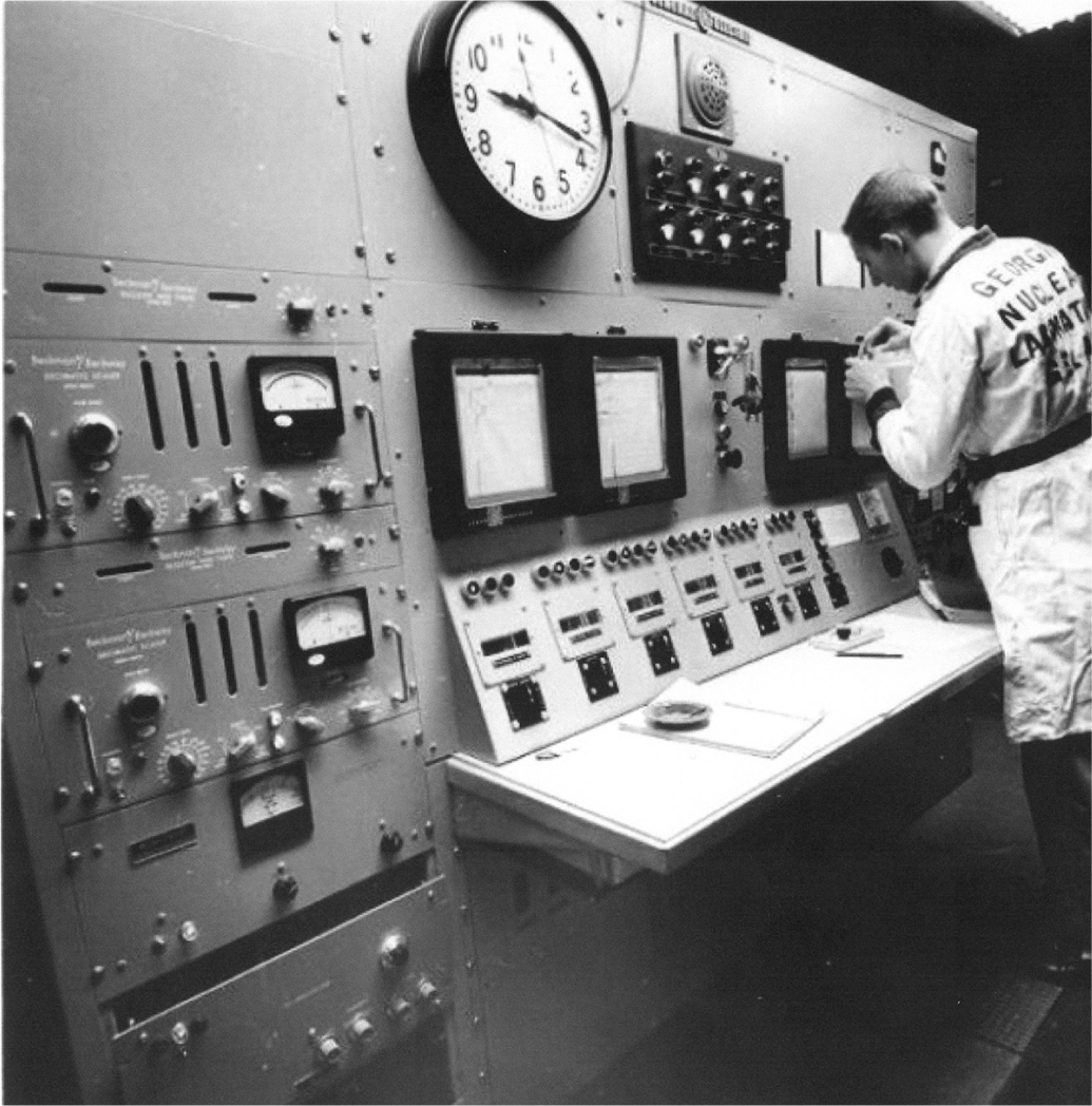
Chapter 2. Billy Statham, reactor operator, standing at the control console for the REF reactor. He is changing a roll of paper in a pen-chart recorder.
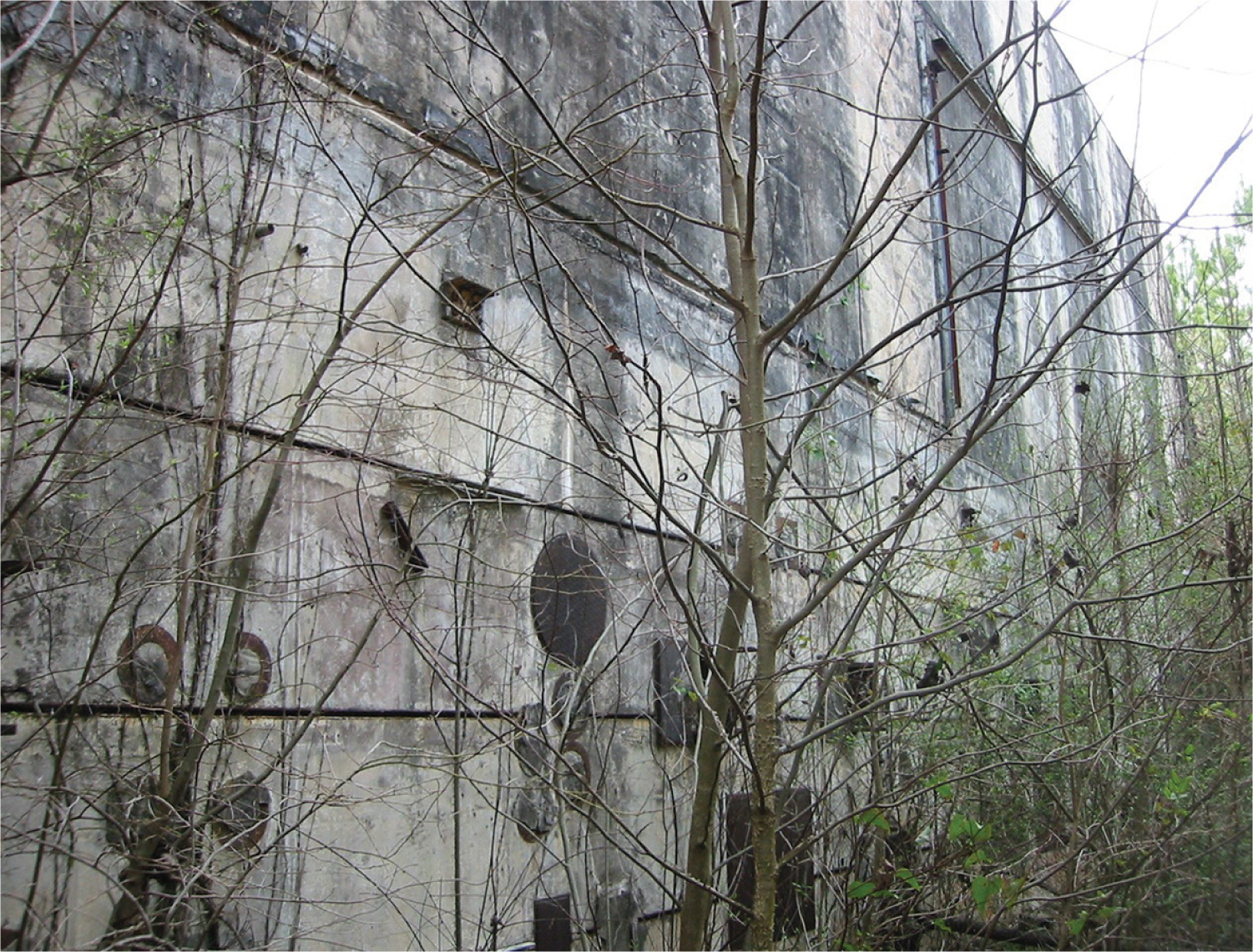
Chapter 2. The east side of the hot cells as they now appear. All window and manipulator penetrations have been blocked with steel plugs.

Chapter 3. Our palladium electrode sawed off a one troy ounce ingot of precious metal.
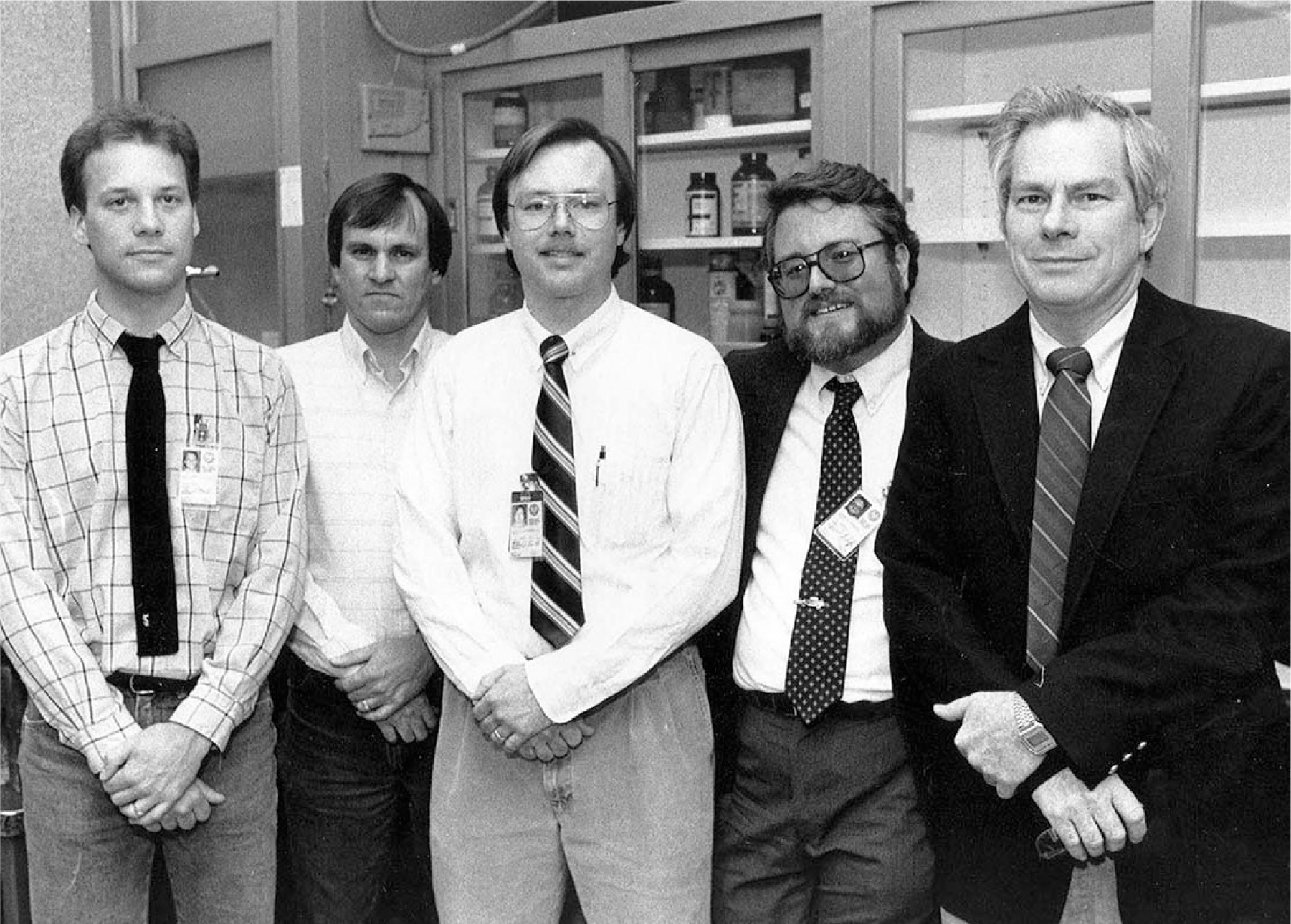
Chapter 4. The team, in RM127. From left to right, Gary Beebe, Darrell Acree, Rick Steenblik, the author, and Billy Livesay.

Chapter 4. Billy and Darrell preparing to clear our palladium of any existing hydrogen.
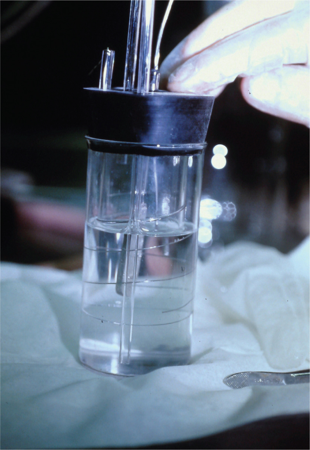
Chapter 4. The Georgia Tech cold fusion cell.
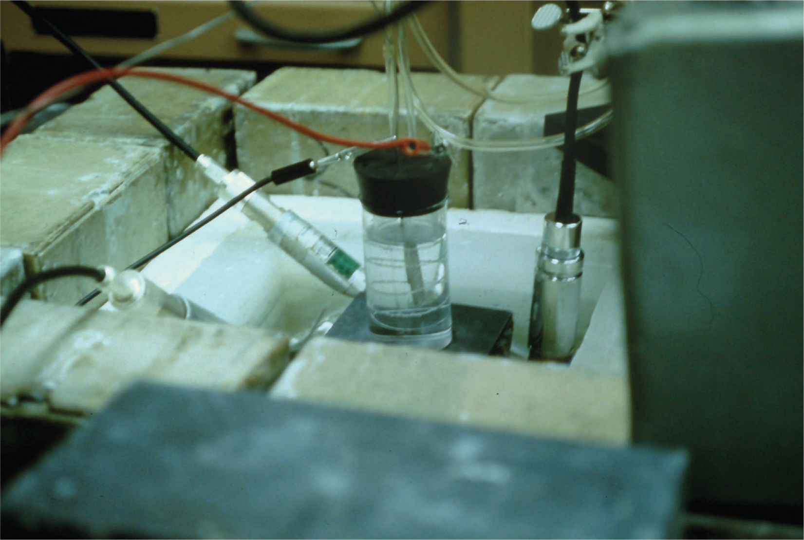
Chapter 4. The cold fusion cell, before being lowered into the graphite block. Three BF3 neutron counter tubes are immersed in the cooling water.
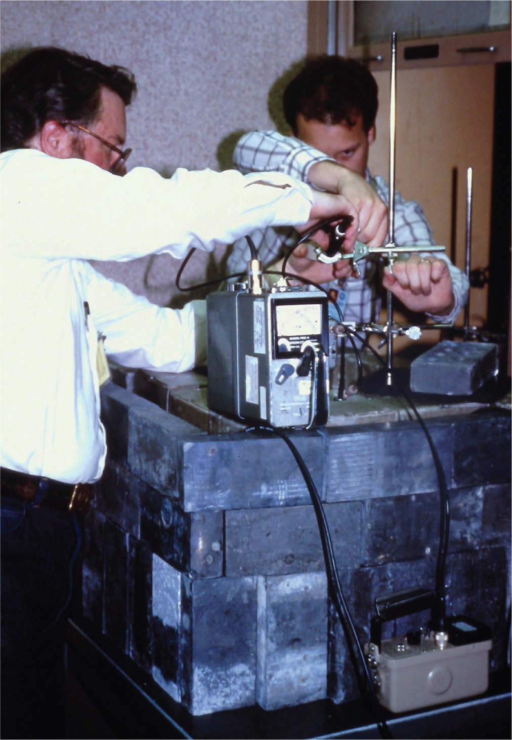
Chapter 4. Gary and I working on the detector setups. In this picture, the lead castle atop a wooden table is clearly visible. A portable neutron detector sits on the boron bricks inside the castle walls.
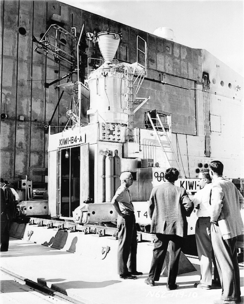
Chapter 5. KIWI-B4-A set up at Test Cell A, in front of the combination blast and radiation shield used to protect the data-recording instruments.
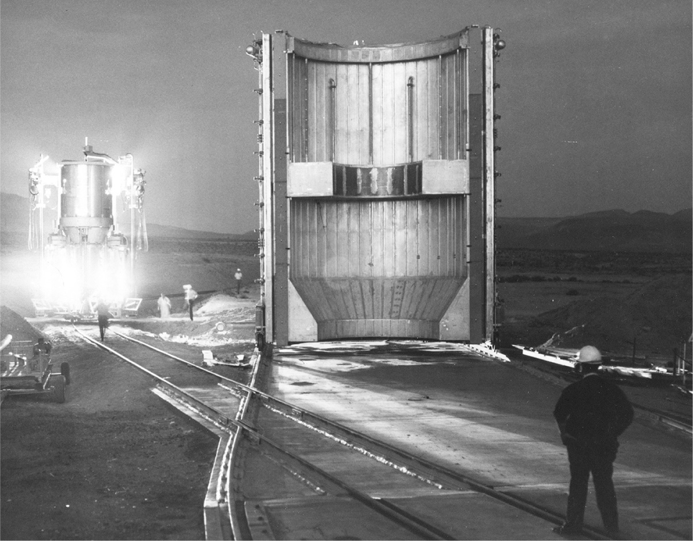
Chapter 5. Setting up for an NRX test. This is half of the clamshell vacuum chamber. It clamps around the engine and simulates the operating environment of outer space.

Chapter 7. The 27-inch cyclotron at RIKEN. It is shown with the accelerator chamber racked out from between the poles of the enormous electromagnet that accounts for most of the weight of this machine.
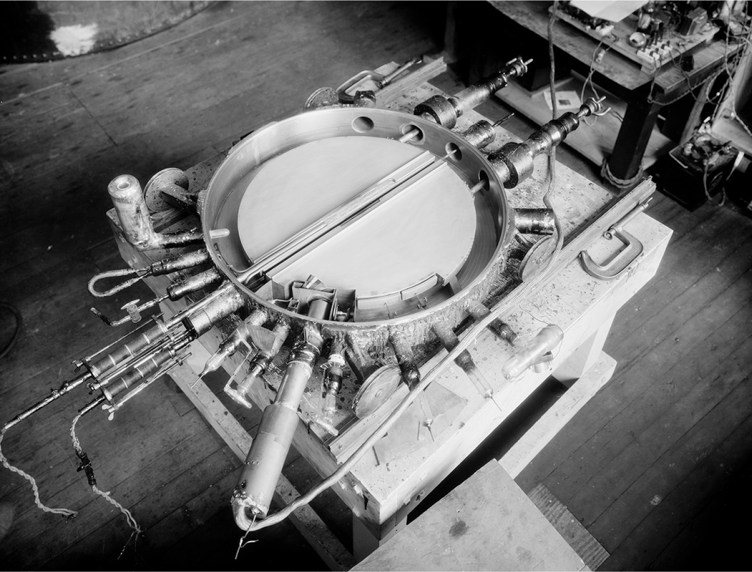
Chapter 7. The accelerator chamber of the 27-inch cyclotron at RIKEN, on the bench and ready to be installed in the magnet gap.
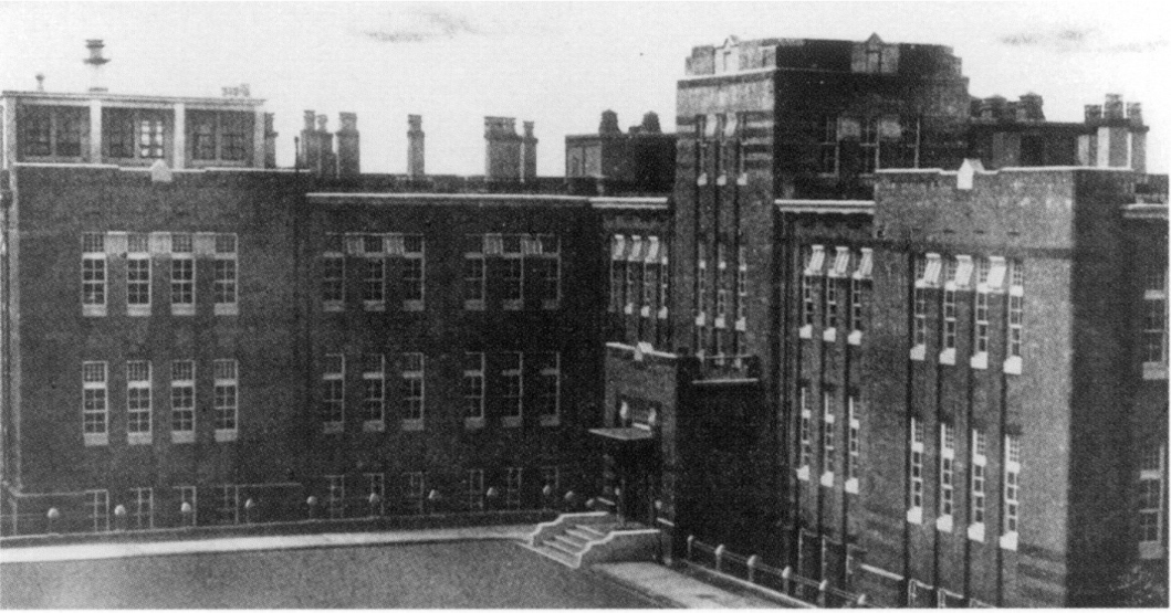
Chapter 7. The RIKEN laboratory before the war.
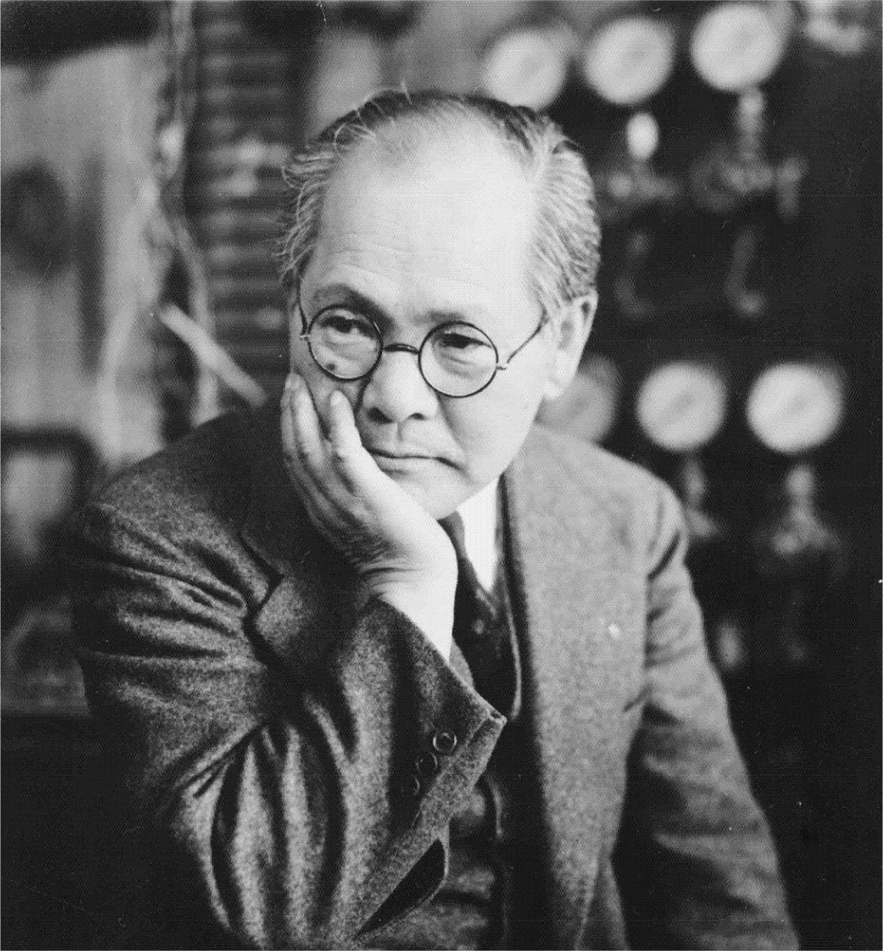
Chapter 7. Dr. Yoshio Nishina.

Chapter 7. A big piece of a Japanese cyclotron being dumped into Tokyo Bay.
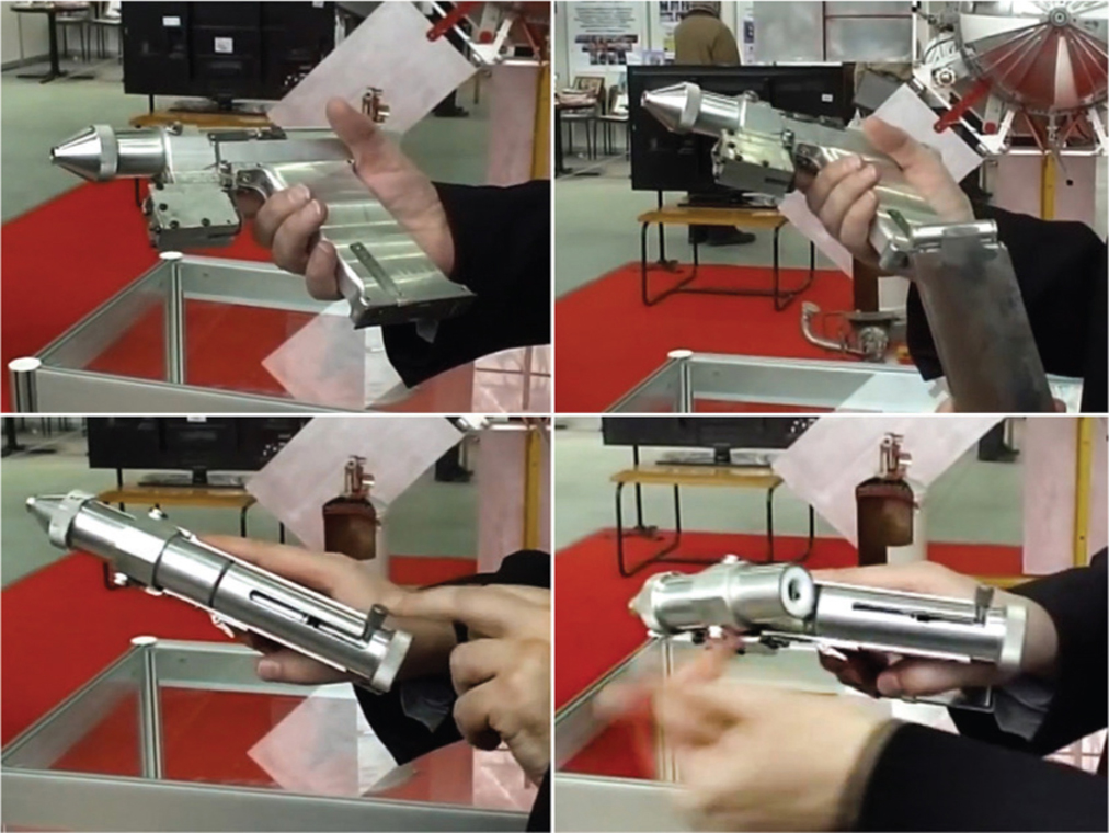
Chapter 8. From the top left, moving clockwise: The prototype Soviet laser pistol to be used for defense in Earth orbit. The ejected magazine containing disposable zirconium flash cartridges. The breech snapped open to eject a spent cartridge. Push the lever to the left to load a cartridge and pull the trigger to fire.

Chapter 8. The 1K17 Szhatie Soviet mobile laser weapon built at the height of the Cold War in the 1980s. As you can see, it weighs several tons and runs on Msta-S tank tracks, and therefore it may be impractical for criminal use. It may have taken a half an hour to charge up the capacitors for a single shot, so its value as a military weapon was also questionable.

Chapter 8. A cluster of four Soviet radio-thermal electrical generators, filled with enough strontium-90 to run a lighthouse. A small block of strontium-90, which was an inexpensive by-product of nuclear power reactor waste, gets so hot it glows dull red.

Chapter 9. The original Victoreen Model 247, from 1943. It turned out to be too delicate for use in the beach landing at Normandy in 1944.

Chapter 9. The Victoreen Model 247A radiation survey meter from 1946. It met all the needs for a rugged, dependable instrument to measure dangerous radiation levels in nuclear weapon tests.

Chapter 9. Costing $299.95 in 1954, the Hoffman Countmaster was one of the most expensive portable Geiger counters available, but it was unique in that it was equipped with a four-decade digital counter having an impressive nanosecond response time. It was appropriate for uranium ore assaying and precision radiation contour mapping as well as field exploration. The countdown clock is mechanical.
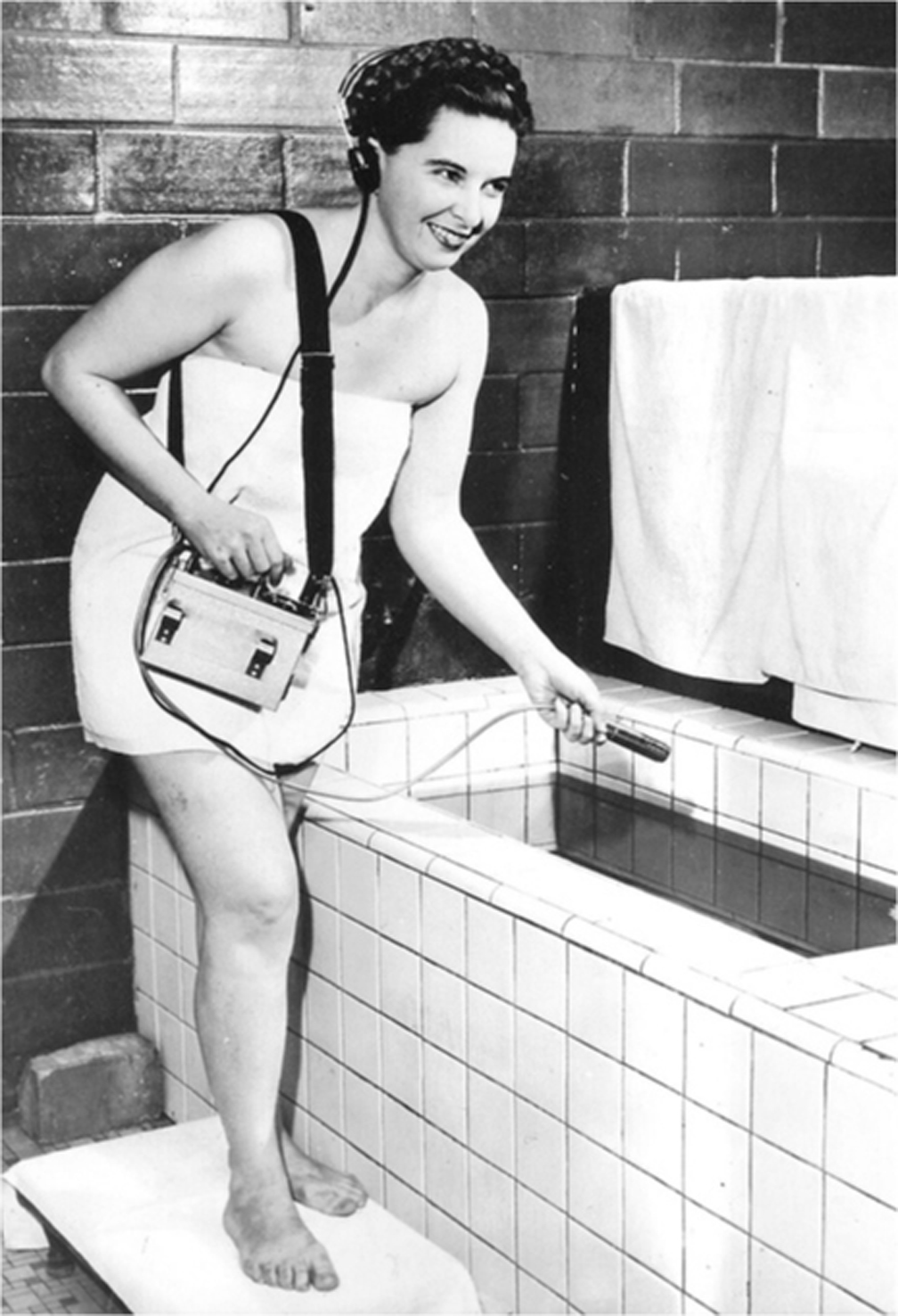
Chapter 9. January 1955, Blossom Barton of Claremore, Oklahoma, checks out her mineral-water bath with a Geiger counter before getting in to make sure it’s radioactive enough. The general feeling about radioactivity was different back then.
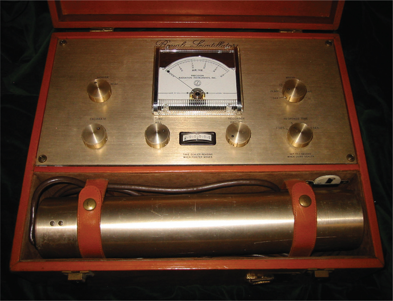
Chapter 9. The author’s gold-plated PRI Model 118 Royal Scintillator, tastefully presented in a leather-covered case, is one of two working examples known to exist. It has a counter function similar to the Hoffman Countmaster, but it is analog instead of digital, showing gamma-ray counts taken during an electronically derived countdown period as a needle deflection on the large meter. It can find uranium in a fireplace brick.
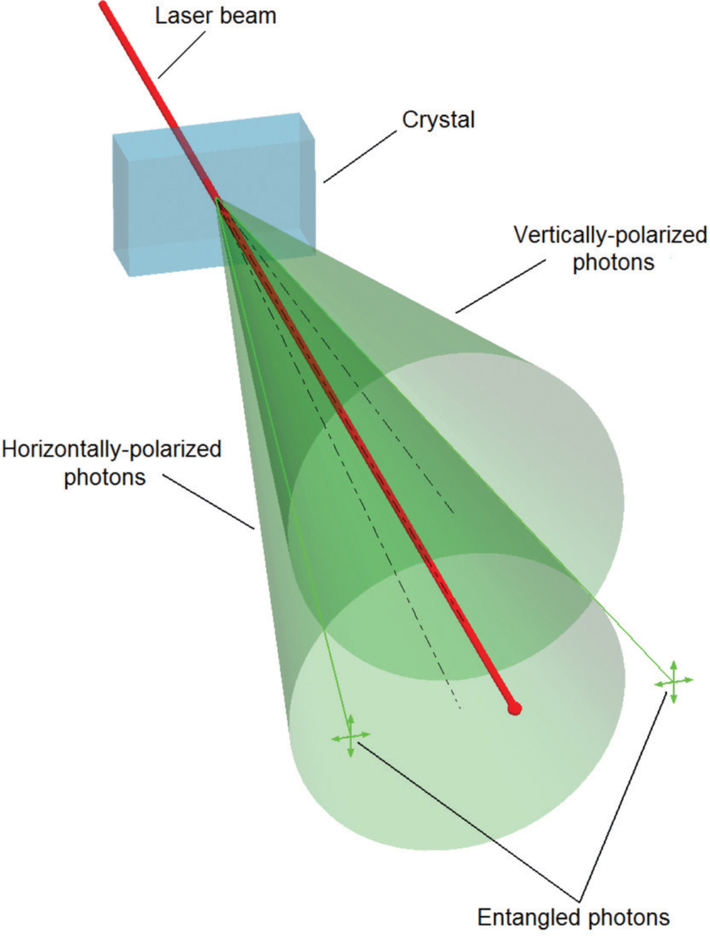
Chapter 10. For the purpose of making entangled photons, a laser beam is directed through a down-conversion crystal. The unused portion of the beam continues straight on, but down-converted photon pairs are segregated into vertically and horizontally polarized examples, exiting the crystal in cone-shaped regions. The lines where the two geometric cones intersect define where to look for the special entangled pairs.
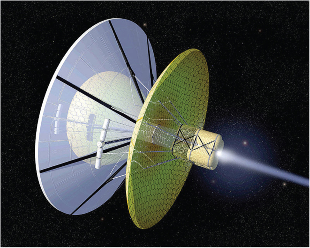
Chapter 10. The Bussard Interstellar Ramjet, showing the large hydrogen collector in front. The visible exhaust is fusion products heated to incandescence.
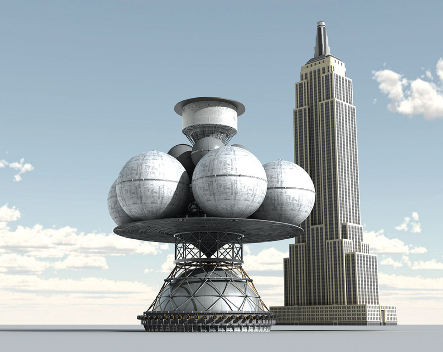
Chapter 10. Just to give an impression of the size of the unmanned Daedalus probe, this is how it looks standing next to the Empire State Building. It is very large, and it will be expensive to build.
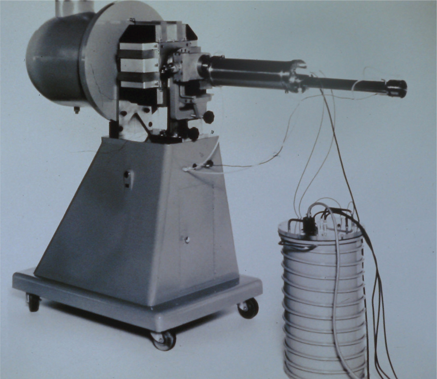
Chapter 11. Judge Ellison’s Activitron, built and sold by the Ellison Company, Atlanta, Georgia. The cylinder in front is the high-voltage power supply. Neutrons come out of the nose-piece, on the right.
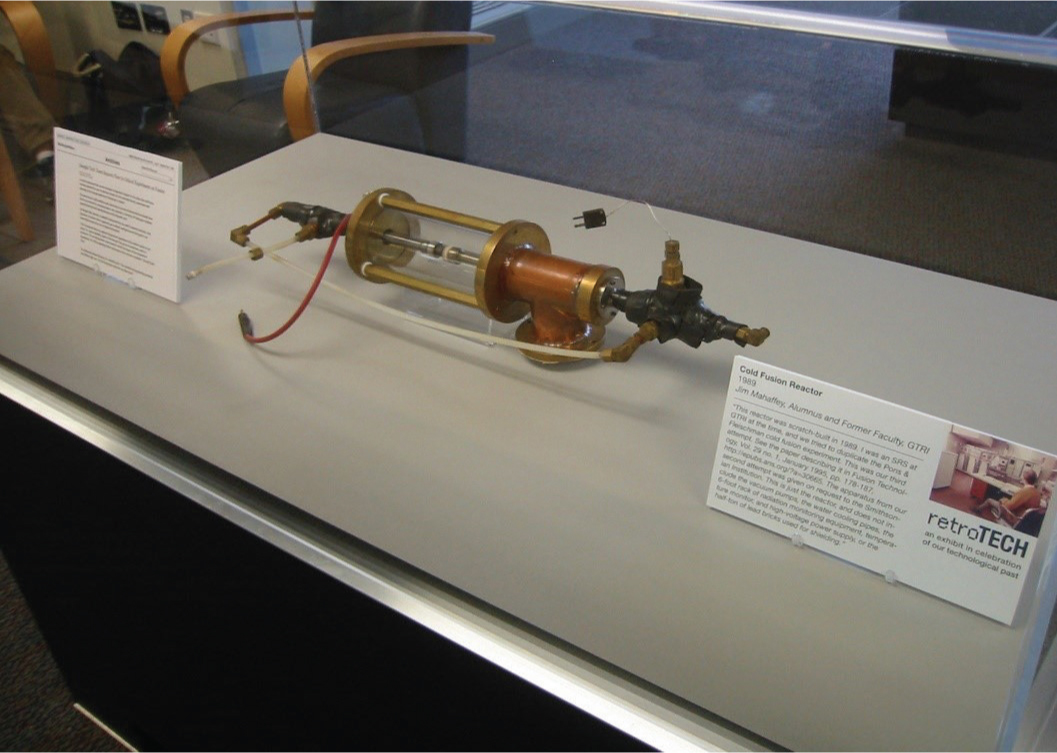
Chapter 11. Our Kucherov glow-discharge cold fusion reactor, on display in the Georgia Tech Library.