CHAPTER 9
THE CONTROL SYSTEM
One very important aspect to any heat pump is the control system. Given that the whole system will have many interrelated components, the functioning of these must be switched on or off automatically when needed, according to a control strategy. An electronic controller is fundamental to all heat-pump units. This controller is also the interface where the user can communicate with the system, interrogate the functions and program their particular requirements. The digital displays can seem quite complicated until you spend a little time reading the instructions. Increasingly, they attempt to be simple so that you can adjust things without too much bewilderment and grief.
Some heat pumps, however, have very simple controls. Whilst possibly missing out on certain refinements of functions, simple controls can have their advantages. It is possibly better to set a simple controller correctly that a sophisticated one incorrectly. Not all users have the aptitude or inclination to think through any required settings, but if you have a good installer, they should walk you through the controller and make most settings for you.
The temperature levels that we like to live in are in many ways what we grow used to. A temperature of 21°C is the norm and is generally accepted for older people. Some people tend to live in temperatures of up to 23°C and dress very lightly. Others tend to happily economize in temperatures below 20°C and dress accordingly. The shift towards lower temperatures might involve some short-lived discomfort while you become accustomed to it, but most people get ‘acclimatized’. From then on, you are saving energy and money. And on a more ethical note, although one can live in whatever temperature one wishes, it is worth the thought that over-indulgent heating (expense aside) may not be environmentally responsible.
HEATING SYSTEM SETINGS
Heating systems generally have two temperature settings:
 The room temperature thermostat.
 The setting of the water temperature circulating around the radiators.
The Energy Saving Trust advises that turning the room thermostat down by 1°C can save up to 8 per cent on fuel use. Your house will not be quite so hot, but significant energy can be saved.
Further to this, heat pumps and condensing boilers are sensitive to the second setting – the heated water passing through them. For every four degrees reduction in this temperature, about 10 per cent can be saved on heat-pump running costs (for the same delivered heat). It may be possible to reduce the setting and still achieve the same room temperature, hence reducing input, for the same total heat output.
To put it another way, if you can manage to reduce the water temperature that your heat pump ‘sees’, but still maintain the same room comfort, you can save on heat-pump running costs.
Simple Controls
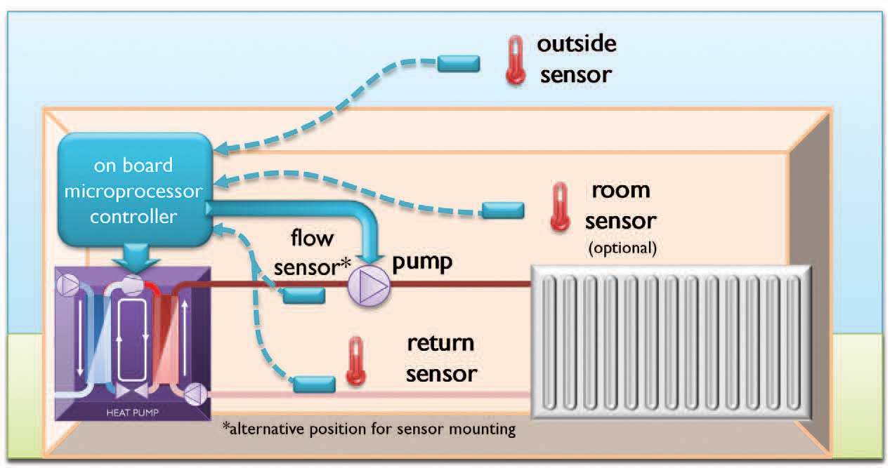
The main function of a controller is ultimately to regulate the heat delivered to the building and to do so whilst achieving the best energy efficiency. In its simplest form, it could involve simply a room thermostat to switch the circulation pump and a thermostat on the heat pump to control the compressor to regulate the water temperature that the heat pump produces.

Simple controls. Beware of ‘clever’ room thermostats that can pulse. Not all are compatible with heat pumps.

A simple control knob.
Note: on the diagram on the above, COP figures have been superimposed on to the scale as examples that roughly relate to the temperatures on the dial.
If a simple thermostat is used on the heat pump, it will need to be set at a temperature that is high enough to give adequate room heat for the emitter system that is used. As we know, the heat pump should heat water at the lowest possible temperature so that the energy efficiency is kept high, but not everyone would have the inclination to make regular adjustments. For this reason, an automatic method of reducing the setting was developed. It is referred to as ‘weather compensation’. This is covered over the next few pages.
Integrated Controllers
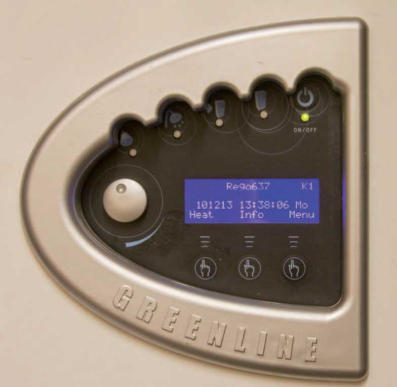
Whilst these home screens might seem daunting at first, they are now mostly intuitive to use, and it doesn’t take long for the words and figures shown to become familiar. They generally show, at-a-glance, the mode of operation and various temperatures and so on. As time goes on, they seem to become more user-friendly.

A microprocessor controller integral to the heat pump.

Ecoforest.

Thermia.

Kensa.

Worcester Bosch.
Heat-pump controllers usually have the following facilities:
■Heat-output control.
■Time and setback (e.g. lower night-time temperature) functions.
■System information (hours run, compressor starts, various temperatures).
■Control of top-up or back-up auxiliary heater (bivalent/hybrid control).
Your commissioning engineer may have access to a whole list of further parameters, which may include: summer cut-off temperature, anti-cycling delay, speed limits, hysteresis (differential), bivalent point, temperature limits and so on. Don’t worry if that sounds daunting, you can remain blissfully ignorant of such issues if you wish. However, you should always get a copy of these parameters when your system is commissioned. This could be invaluable information for future engineers visiting your site and needing to re-program your controller.
GETTING THE BEST FROM YOUR CONTROLLER
Your user instructions will tell you how to set up your system and these should be read very carefully.
There are one or two tips that might be of interest to those of you keen to minimize your energy use:
 The importance of reducing the settings to the lowest possible temperature cannot be emphasized enough. If the heated water reduces by only 2°C, you are likely to save about 5 per cent on compressor running costs. This is over and above any energy savings due to slightly cooler rooms (see note below).
 Periodically reduce your heating curve (weather compensation) a little bit. If you don’t feel colder over the following days, then leave it at the lower setting (remember: this will adapt as the weather changes).
 If you have a simple fixed-setting thermostat, adjust it month by month to suit the weather and to suit your needs (don’t forget to turn it down in spring!).
 If you are able to program ‘off’ periods for the hot tap water, then try to arrange the ‘off’ time to happen before the end of a period of potential use. This can tend to make the bottom section of the cylinder cold. When the ‘on’ happens, the system starts heating the cold water and does so at a higher energy efficiency. Whilst promising a modest saving, you run the risk of running out of hot water during an ‘off’ period. This may, or may not, be a priority for you.
 Even if you choose to heat your house continuously, it can be worth programming a set-back of just 1 or 2°C lower, such that your unit is encouraged to rest a little for maybe two periods over 24 hours. This encourages some longer run-times, which is usually beneficial.
 Reducing too many TRV radiator valves might compromise the heat-pump’s energy efficiency.
 Ensure that any top-up heater is not working more than you would like it to. There are usually means to limit this. Read your user instructions.
 Browse your user instructions carefully.
Note: Dropping the temperature too far, on some systems, can cause the compressor to stop and start (short-cycling). This could increase energy use.
Keeping the heated water temperature as low as possible is key to low running costs.
Weather Compensation
This control method automatically varies the heated water temperature dependent on an outside air-temperature sensor. This is the recommended way of control and is particularly suited to ground- or water-source systems in average to well-insulated and lightweight houses. It can potentially save a significant amount of energy, so is the default setting for almost all controllers. The graph below illustrates a simple example of weather compensation control.

Graph illustrating weather compensation control.
The horizontal axis shows outside temperature, the vertical shows the heated water temperature of the heat pump. One of the example heating-curves, A, B or C, must be selected in the controller.
If, for example, curve B is chosen, then the return water temperature would be 35°C when it is zero outside. This may be sufficiently warm for under-floor heating (the flow could be 41°C, see box below). As the outside temperature gets colder, the water gets warmer, thus giving more heat to the room. Conversely, the settings will automatically reduce the water temperature as the outside conditions gets warmer. This control maintains the minimum possible temperature for the given outside conditions, thus the maximum energy-efficiency is achieved for the given heat demand.
In a house with radiators, then curve C would probably be needed. This will give higher temperatures resulting in lower energy-efficiencies, as expected with radiators.
Please note that in real life, the curves would offer a finer adjustment. Most controllers would also allow maximum and minimum limits to be programmed in.
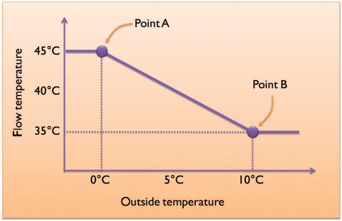
The figure below shows an alternative weather-compensation control. Here, two points are programmed in for specific outside temperatures. In the example given, the flow temperature will be at 45°C for any outside temperature below 0°C and will be at 35°C at anything above 10°C, with a sliding scale in-between. The four temperature values can be changed in any direction required. One advantage to this control is that it easily allows a maximum or minimum limit:

An alternative method of weather compensation control.
■In an old, stone building where the thermal mass of the walls require a radiator temperature that is never below a certain temperature.
■Where the occupier wishes to ‘cap’ the maximum temperature, thus limiting the maximum COP.
This control can be a little more tedious to set and possibly a little more perplexing than the options A, B and C on page 107.
THE DIGITAL TEMPERATURE DISPLAY
It is very important to know if the reading refers to the flow temperature or return temperature.
At concept stage, we often consider the flow temperature, but the controlling sensor is commonly on the return pipe. This may typically be 5°C or 6°C colder than the flow. It is sometimes necessary to add or subtract this amount when making comparisons.
Variable speed inverter drive systems, which are increasingly common, control using a sensor on the flow pipe. With these systems, things are a little more straightforward. For example:
 Standard ground-source with flow of 40°C and return of 34°C – display shows 34°C (on most models).
 Japanese-style inverter-drive air-source with flow of 40°C and return of 34°C – display shows 40°C.
Both examples are operating at the same temperatures.
Weather Compensation Pros and Cons
Advantages:
■Helps to reduce the working temperature to the lowest required at any time.
■Potentially increases COP by a considerable amount and is recommended.
Disadvantages:
■In old, solid-walled buildings and exceptionally well-insulated buildings, the outside temperature is not necessarily the best indicator of actual heat requirements at any one time.
■Outside air-sensors may not represent heat needs, since it ignores direct solar gain.
■For air-source systems, the automatically increased setting may increase the run time during colder nights, this could encourage it to run when the COP is lower.
All in all, weather compensation in some form will usually save a reasonable amount of energy. At best it can save a great deal. It must, however, be set up correctly. This is usually best achieved by trial and error.
Air-Source Weather Compensation Anomaly
Weather compensation automatically increases the water temperature in the heating system when the outside temperature drops. On a cold, frosty night, this control will make the heat pump operate at a high temperature and therefore at a lower COP; however, the middle of the day could be relatively warm. If the building being heated were solid stone, then some advantage could be taken by running the unit in the day, thus storing up some heat generated at a high COP. Indeed, air source and heavyweight buildings could be a good match. For such buildings, a better scheme may be for the controller to take the average temperature over 24 hours and adjust its curve setting on a 24-hour basis. This would have a worthwhile effect of slowly adjusting the control as the seasons change. For the current systems on the market, it is advisable to use some degree of night setback. As time goes on, controllers will no doubt become more intelligent in such matters and it is only a matter of time before the weather forecast data are fed directly into the heat-pump controller.
Other Settings
All controllers have various screens for system information. This should include a record of the total hours that the heat-pump compressor and the auxiliary heater have clocked-up. This is worth keeping an eye on. Note down the hours, and the date and time.


These screenshots from Ecoforest and Kensa controllers give plenty of good diagnostic information for your service engineer, or for curious heat pump owners.
Some heat pumps allow you to switch off the electric heater. However, care should be taken to ensure that any Legionella protection is still satisfied.
Each heat pump has its own features and limitations. It may be worth exploring these by talking to not only installers, but other owners of the product.
One little detail that is worth bearing in mind: if the night set-back temperature is set too low, or the heat pump timed-off altogether, then it may take a considerable time to get back to a comfortable temperature in the morning.
In a very few heat pumps, the electric ‘boost’ could come on automatically after a certain run time. This should be adjustable. It should go without saying that having the compressor running is always preferable to the electric back-up heater.
Smart Metering
The supply utility companies are keen to smooth-out peaks and troughs in electricity demand. This has led to some European countries trialling systems where they can switch off non-urgent loads like heat pumps. No doubt this is a topic that we will need to embrace in the future and it is maybe something that we need to be ready for.
Electrical Supply and Inverter Drives
Heat pumps have quite big electric motors in them, and in the past, larger models have required three-phase electrical supplies, which are uncommon in homes in the UK. One issue is the brief starting surge that could dim lights. However, all models should now include Soft Start to mitigate this.
The vast majority of air source units now have inverters. This means that the compressor varies in speed as required. This is a big advantage for air source that operate in widely differing weather conditions.
Increasingly, new ground source models have variable inverter motors. This has several advantages: the energy-efficiency of the motor can be very high. Inverters also go hand-in-hand with electronic expansion valves, and these optimise the inner workings of the refrigeration circuit, and can improve COP considerably. There is also no starting surge since they start slowly. Models with inverters do not usually need a buffer cylinder.
On the downside, the heat pump will have some very sophisticated electronics: if something were to fail, then the repairs could be expensive. That said, all modern cars are in the same category, and probably far more complex than a heat pump. The older fixed-speed non-inverter units have fewer things to go wrong and would be easier to mend.
Locating a Heat-Pump Unit
The working mechanism of a heat pump is essentially the same as that of a fridge. The compressor at the back of a fridge has no sound-attenuation measures, deemed unnecessary for an item in a kitchen. Heat pumps have more powerful compressors that give out more noise; however, they are usually lagged with a jacket and the unit casing is usually lined with sound-absorbent material. That said, heat pumps do emit a noise that can tend to be carried through slight vibrations in the building. Noise is very subjective. What is an irritant to some is of no bother to others. Whilst sound levels vary model to model, it is generally accepted that one would not install a heat-pump unit below or adjacent to a bedroom or living-room, and care should be given to the base that the unit is placed on. Pipe runs can transmit noise, so sound-deadening hose connections are often used.
It is not always possible to fit a heat pump inside a small house, but it can be possible to accommodate it in a small frost-free ‘hut’.

Specially built insulated ‘hut’ housing the workings.
Air-source heat-pumps must be carefully located, since noise could potentially irritate neighbours. For that reason, they will require planning permission. That said, the latest models are very quiet.
It would seem advantageous to locate an air-source unit in a warm, sunny location. This might be the case, but given that the unit may process up to 1m3 of air every second, the solar heat that may have built up over hours can quickly be exhausted. The advantage may therefore only be slight.
The buffer cylinder (if one is fitted) is always better located inside the building, this avoids un-useful heat losses in winter. The hot-water cylinder location is more important. If pipe runs from heat pump to cylinder and from cylinder to taps are too long, then energy will be wasted to a certain extent. Ideally, these pipe runs should be relatively short.
Servicing
One of the selling points of a heat pump is that it requires very little maintenance, but any piece of mechanical equipment will need servicing from time to time. Boilers require an annual service and suffer from a build up of residue from the combustion of gas in air. Given that typically 1,000m3 of gas per year are burnt, then this should be no surprise.
Heat pumps are like fridges, the inner workings can keep going with no attention whatsoever. The refrigeration components and their connecting pipework were evacuated during manufacture and filled with an exact weight of refrigerant. This fluid tirelessly travels around the heat pump in clinically clean conditions; the refrigeration circuit is therefore inherently reliable and requires little or no servicing. Water and brine circuits may, however, need an occasional check. Both the source and emitter circuit will have pressure gauges and these should not drop below a certain level. Very occasionally a top-up may be required and any loss in pressure should be investigated and the problem should be resolved. It is very important to know the strength of glycol concentration in the source pipes, since serious problems could result if the degree of frost protection is insufficient. This concentration should not change over time unless, for example, the glycol (brine) circuit has been inadvertently topped up with water. A filter in the circuit is mainly there to catch debris from installation process. It should not be a regular ongoing concern.
It is only the open-source system that may need regular maintenance for cleaning and filter changing of the source water. Ducted air systems also have filters and it is not unheard of for owners to be unaware that certain filters exist.
One advantage to the advanced digital controllers, as now fitted to most heat pumps, is that they can usually tell you lots of useful information about your system. They also have good system protection and good fault analysis.
You should find the following:
■Flow and/or return temperature.
■Source temperature.
■Hot-water temperature.
■Total compressor-run hours (from first switch-on).
■Total second heat-source hours (if fitted).
■Number of compressor starts (from first switch-on).
■History log of any alarms and faults.

Possible fault conditions.
Some systems give more, some give less. However, this information can be very useful if you want to ensure that your heat pump is working at its optimum efficiency.
If you are interested in monitoring your system, and you do not already have one, it could be worth getting your electrician to fit an electric kWhr meter on to your heat-pump’s supply. Reconditioned meters are very cheap and would take the guesswork out of what proportion of your electricity is used by the heat pump. There are now a multitude of devices available if you are minded to do some rudimentary or intensive monitoring of your system. Internet monitoring and control is now becoming more common.
With built-in controllers you should be able to rest assured that, in the unlikely event of something going wrong, the system will simply shut-down and flash to alert you to attend to something, or call an engineer.
Having implied that heat pumps need little attention, like any mechanical device, things can fail. The list shows some examples of potential faults. Each heat pump will have its own list of faults and suggestions for a remedy.
 The room temperature thermostat.
 The setting of the water temperature circulating around the radiators.


