One of the end frames.
In a normal household situation the baseboard will probably have sufficient lighting from the main room light, although problems can occur when you are viewing the layout. If the room has a single central source of light, your body is more than likely to be between the light and the baseboard, creating a shadow on the area you are viewing. In exhibitions there is considerable uncertainty as to the quality of light and its direction. Exhibition halls are usually filled to capacity with every corner being utilized. The lighting in a whole variety of halls can vary tremendously. Lighting in a church hall and in a gym or dining area will be totally different, as will lighting in a foyer and a corridor. If you are planning to exhibit and wish to display your layout to the greatest effect, the best answer is to provide your own lighting.
If you have your own permanent railway room it is logical to light the room to meet the needs of both the layout and your activities in the room, but if you are operating the layout in a variety of locations, you need to take your own lighting system with you to gain the best effect for your layout.
A well-lit layout attracts people to view your layout and they stay longer. There are a wide variety of lighting systems but your lighting needs to comply with basic rules. Light needs to be above the layout and needs to give relatively even illumination, but must not shine in the viewer’s eyes. At exhibitions, if you operate the layout from the back, you need to make sure that the lighting board does not obstruct your eye-to-eye contact with the viewers of your layout. Time after time lighting boards hide the operators’ faces from the viewers. In some cases you feel that this is intentional, as operators in quite a few cases are more interested in operating the layout than in making any contact with the paying public. I understand that, in some cases, exhibitions are the only time that operators get the opportunity to work their full layout, but the most successful layouts have operators at the side or at the front, so that discussions can be opened up with interested visitors.
Posts to hold the lighting gantry need to fix to either the sides of the baseboard or the rear of the board. The gantry needs to be level with the front of the display at a suitable height – usually 800mm (32in) above the track bed. Exhibitors mainly used spot lights, either built in or clipped to the gantry, but with the advent of down lighters and, more recently, with LED lights, lighting gantries are usually slightly smaller than in the past. Each metre of baseboard needs a couple of lights to provide adequate lighting. One way is to construct a box unit the same length as each baseboard, but having one side much longer to provide a shade for the lights and a front for the unit. If installing down lighters in such a box, all the wiring can be inside the box. The top of the box should be ventilated and allow wires to pass along the full length of the gantry box before passing along and down the support to the power supply. All lighting circuits should be terminated with an ELCB (Earth Leak Circuit Breaker) if you are using mains voltage. The inside of the box needs to be painted matt white to give an even spread of light.
The simplest lighting can be achieved with a frame and clip-on spotlights attached, but this tends to detract from the layout and also light can easily shine in the public’s eyes.
For my folding layout I have designed a simple lighting gantry, which can be integrated into the folding baseboard unit. When the unit is closed for transportation, the sides with the dowels are joined together with two wooden straps.
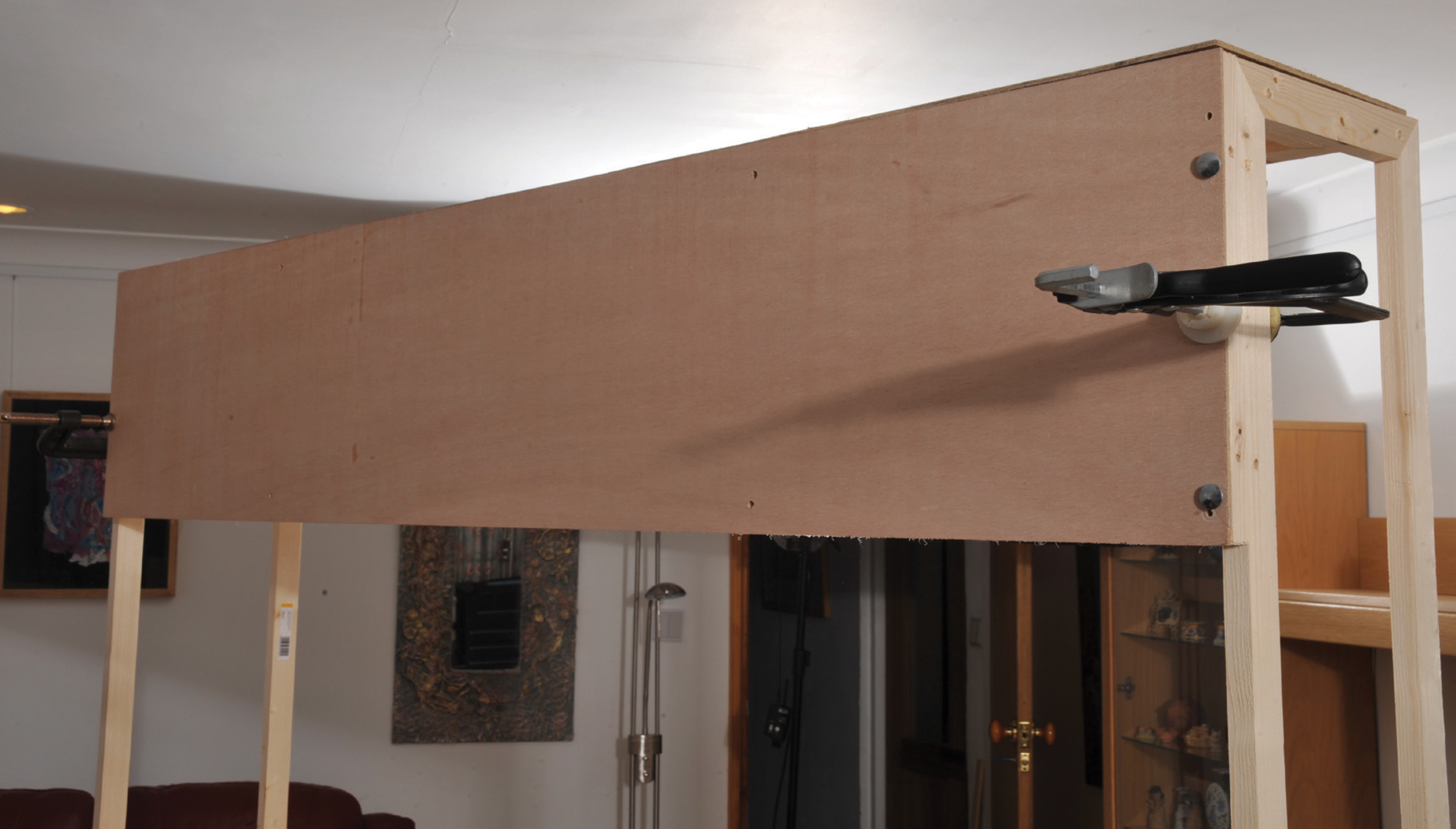
The other side of the closed unit is completely flat and the two halves of the baseboard have been joined together with the front and top of the lighting gantry.
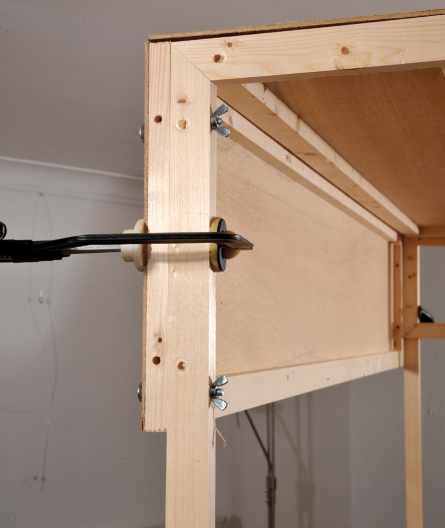
The first task is to make two support frames out of softwood. The frames are the uprights and they need to be bolted to the ends of the baseboard with coach bolts and wing nuts. One of the frames will need to have a second small frame inserted to support the top of the light stand, which will be slightly smaller than the front (in order to fit inside the stand front when being transported). The supporting uprights are constructed in 18mm (¾in) × 34mm (1½in) softwood. They need to be the height from the base of the baseboard to the top of the front board, plus the viewing height. This will vary according to the height that the baseboard is from the ground, but with a baseboard 1,000mm (39in) from the ground and a front board of 300mm (12in) deep, the frame will need to be approximately 1,050mm (41¼in) from top to bottom. I have made the uprights 260mm (10¼in) wide, So that I do not impair the fixing of any legs and so that the top fits inside the front for carrying.
One of the end frames.

Both end frames fitted to the sides of the main board.

The additional frame to accommodate the slightly narrower top of the lighting panel (so that it will sit inside the frame of the front panel).

The two slightly different frames.

The two end frames with side panels fitted.
Identical-sized panels are added to each end to create the ends of the light box. They are the same height as the front panel, which is 305mm (12in) deep and runs the full width of the baseboard. The depth measurement is exactly the same as the width between the outsides of the frames of the two baseboards when they are joined together.
For the front panel of the light box, the softwood frame is cut to the exact size of the plywood (this can be either a butt joint or a mitre joint). The frame is glued together and then the plywood top is added to the glue-covered frame. Both the frame and the plywood are flexible, and to ensure good contact along the whole length when gluing, I have placed two support beams between the trestles. Unlike a solid worktop it is possible to adjust the width between the beams and clamp the plywood, the frame and the support beam together to ensure perfect contact until the glue dries. When dry, the clamps and the support beams are removed.

The front panel frame, glued and resting on beams to permit clamping until dry.
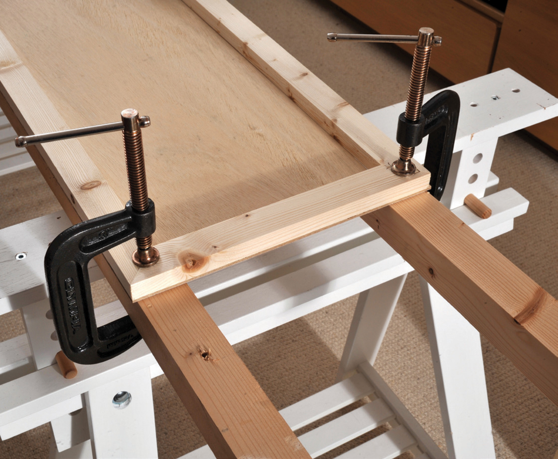
The frame temporarily clamped to the support beams.

The outer frame and plywood front with the top panel frame fitting inside, ready for its plywood cover.
A similar frame is constructed that fits inside the above frame; it is also covered with 3.6mm (1/16in) plywood and will form the top of the lighting gantry. The frame will eventually sit on top of both the front board and the two side upright supports. The plywood top will overhang the frame by 34mm (1½in) at each end and on at least one side. This top is constructed in the same way, again using the support beams until completely dry.
Clamp the front into position, level with the top of the uprights, and drill two holes at each end to allow the front and the frame to be bolted together. The top can be dropped into place and the unit is then ready for painting and the installation of your choice of lighting.

The completed front panel.
The top panel in place.

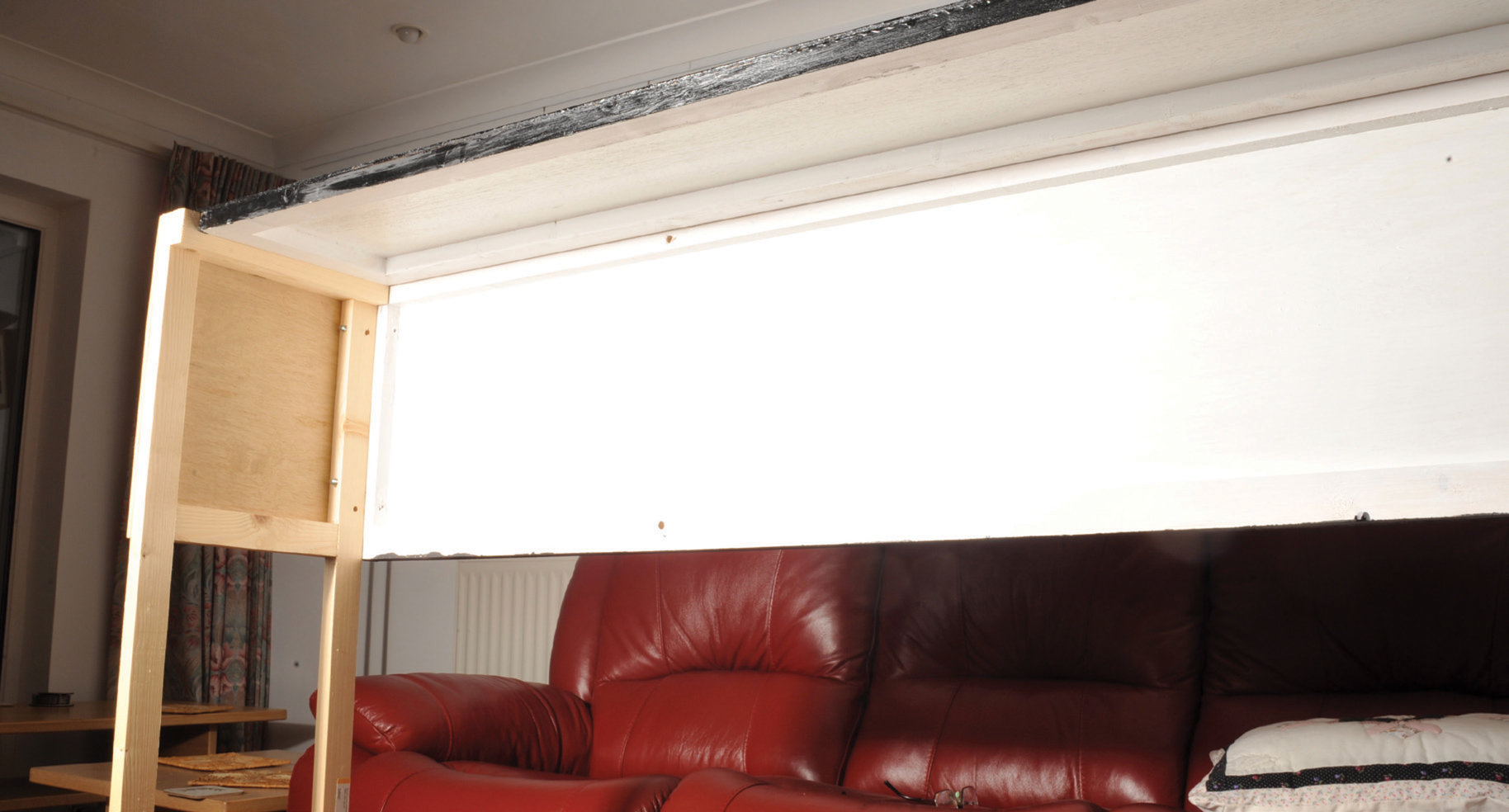
The completed unit showing the top and front panels.
When it is all completely dry, check once again that it will make up and pack away easily. Fit the handles. It may be necessary to re-drill some of the bolt holes as they will probably have acquired a little paint during the finishing processes.
Painted light box.
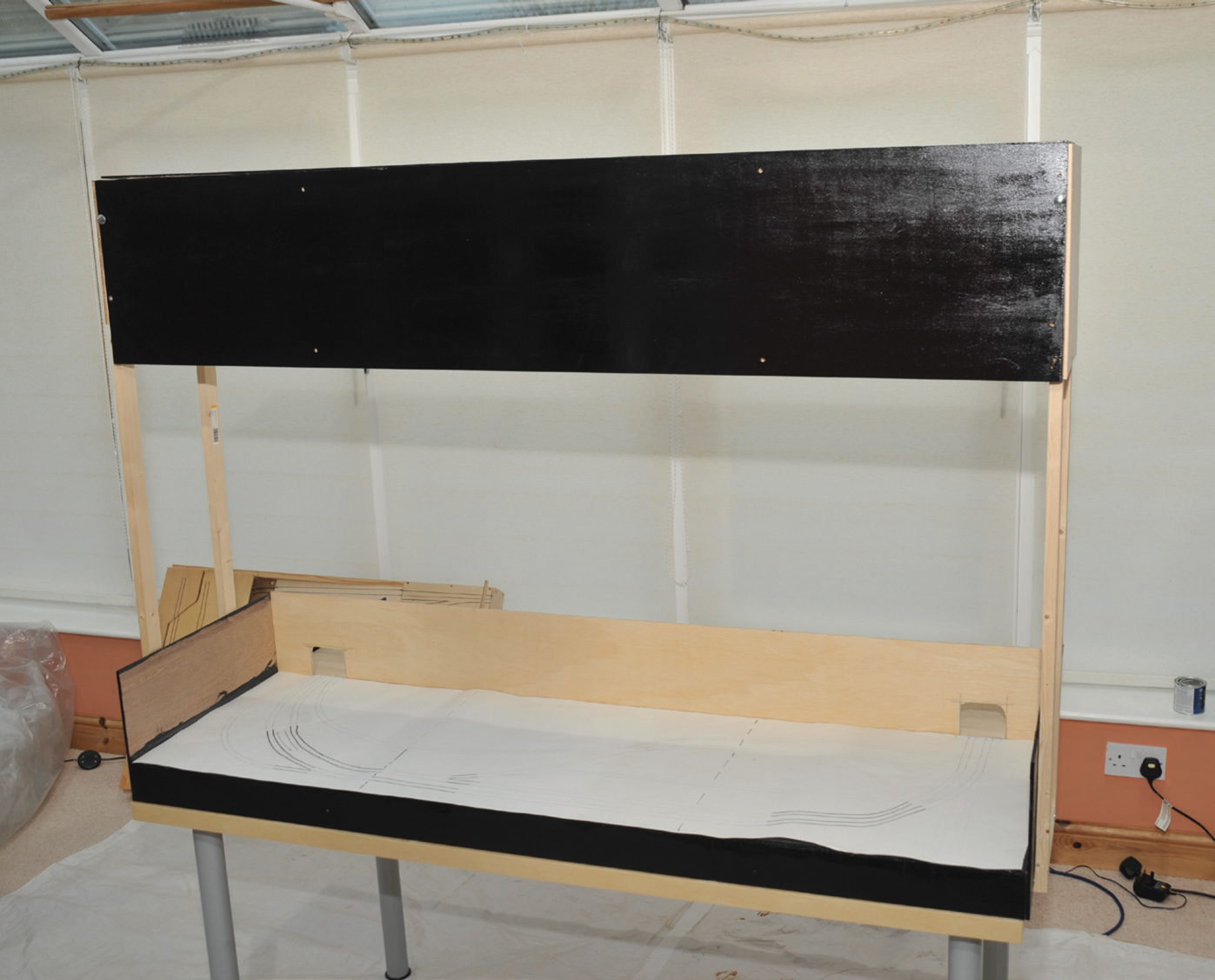
The completed unit.

The closed unit with the lighting box making up one side.