Layout plan marking hidden areas, station and so on.
There is a simple rule when cutting wood, ‘Measure twice – cut once’, and this is equally true of any work on a baseboard. The planning needs to be meticulous to allow for a simple, trouble-free construction. Skimp the planning and you will pay the penalty throughout the construction, and possibly throughout the life of the layout.
There is no point in having a rough sketch. You need detailed drawings showing exactly where the track fits, how steep the curves are, where there are rises and falls, where the platforms fit and whether the coaches and locos will cope with the proximity of tunnels, bridges, buildings and platforms, before you begin any construction. You need to ensure that there is enough room for a head shunt or whether the platform or goods’ yard will hold appropriate numbers of rolling stock.
It is not just the track, but also the electrics: you need to ensure that you can easily wire in points, lights, signals, etc., in a neat and obvious way.
One longer term consideration is whether the proposed layout will give you sufficient satisfaction when it is being operated. If it only has one siding plus a single circuit, you will find it lacks interest after a while. On the other hand, putting too many junctions and sidings or too many running tracks can complicate a layout until it becomes too complicated to work. There are many computer packages that help with design but, at the end of the day, there is nothing more accurate than a full-sized template.
Layout plan marking hidden areas, station and so on.
The simplest way is to purchase a roll of lining paper from a decorator or from one of the DIY stores or even a ‘pound shop’. An alternative is to find a commercial catering outlet and buy a roll of paper table-cloth, which is usually 1,000mm wide. Most people opt for the lining paper as it is far more readily available. The first thing to do is to cut your roll to the exact size of the planned baseboard. This will probably mean joining two pieces side by side for a continuous layout, as lining paper is only 530mm (21in) wide. You can obviously join the two with Sellotape, but that is difficult to draw on, or you can use masking tape or just glue each edge together. Either of the latter two options allows continuous lines to be drawn.
The initial step is to draw lines to represent the outer frame, which will obviously run around the perimeter of the baseboard. The lines should be drawn in ink, so that they are clearly visible when planning your layout.
Next you need to draw thin pencil lines to show the ideal position of the cross-members and central spine, which will be underneath the board. They should be drawn to exactly halve the board width-wise and then the cross-members should be positioned approximately 300mm (12in) apart and an equal distance from each other and the sides.
As I have said these are ideal positions but the whole point of drawing up the full-scale plan is to permit modifications before any cutting is undertaken.
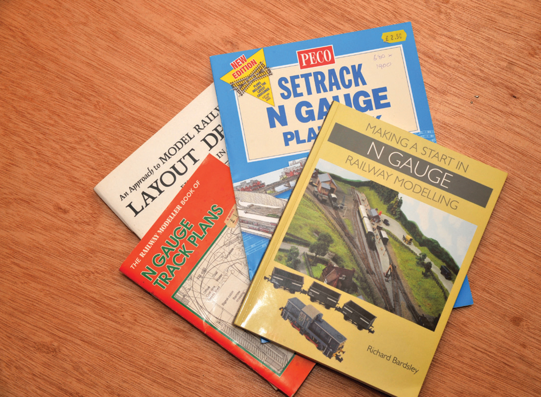
Before you start work on the full-sized version of your layout it is best to use an A4 pad to produce a variety of sketches to help you decide which layout best meets your requirements. Once you have an almost finite design in mind, start to transfer it to the full-sized plan. You must work lightly in pencil as your design will have to be adjusted as you begin to fit things into place. If you have difficulty in designing a track plan, there are a multitude of books on the subject or, better still, you can gain valuable visible operation of a variety of layouts at one of the many shows around the country.
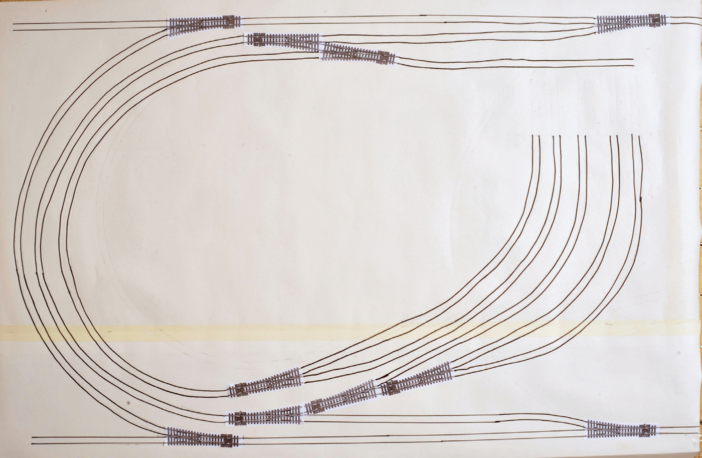
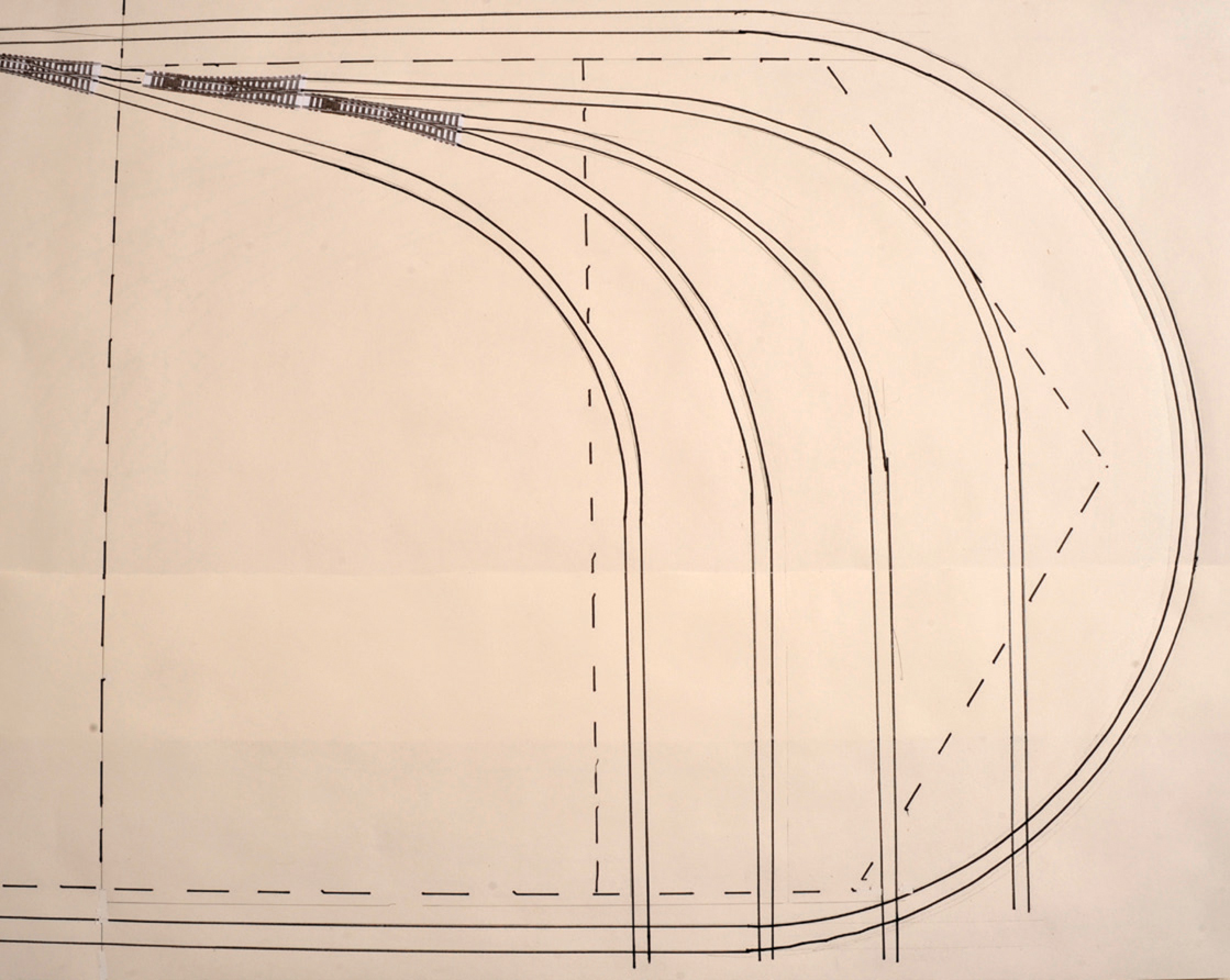
A different layout plan, using turnout (point) templates and Tracksetta gauges plus a ruler.
Once you have pencilled out a track line you need to ensure that you have no potential problems with point motors being directly in line or very close to the projected position of the central spine or cross-members, or, if it is a multiple board layout, that points do not come close to a join. By making some adjustments you will be able to move cross-members or points in one direction or another so as not to be on a join. If it is possible, move the point to a position where there are fewer rail joints between boards, as each joint is a potential problem area, no matter how much care is taken.
If points come in line with a cross-member or the central spine, it is best to adjust the position of these cross-members or the spine so that they do not coincide. All it means at this stage is rubbing out a pencil line and moving it until it is clear of the obstruction above, then redrawing the line representing the cross-member or central spine.
Once you have this completed this, you need to make sure that you have all the angles and curves correct. It is usually best to start with points and PECO are helpful in that, if you go on to their website and search for ‘Turnout Plans’, you will find a comprehensive list of gauges – select the appropriate gauge and code. This will throw up the full range of types and sizes of turnouts (points) and it is probably best to select each one in turn and both save it and print it out. You can print out as many of each one as you need and you are then able to play around with a variety of curves and straights to select the most appropriate for each junction. Place them on the draft layout.
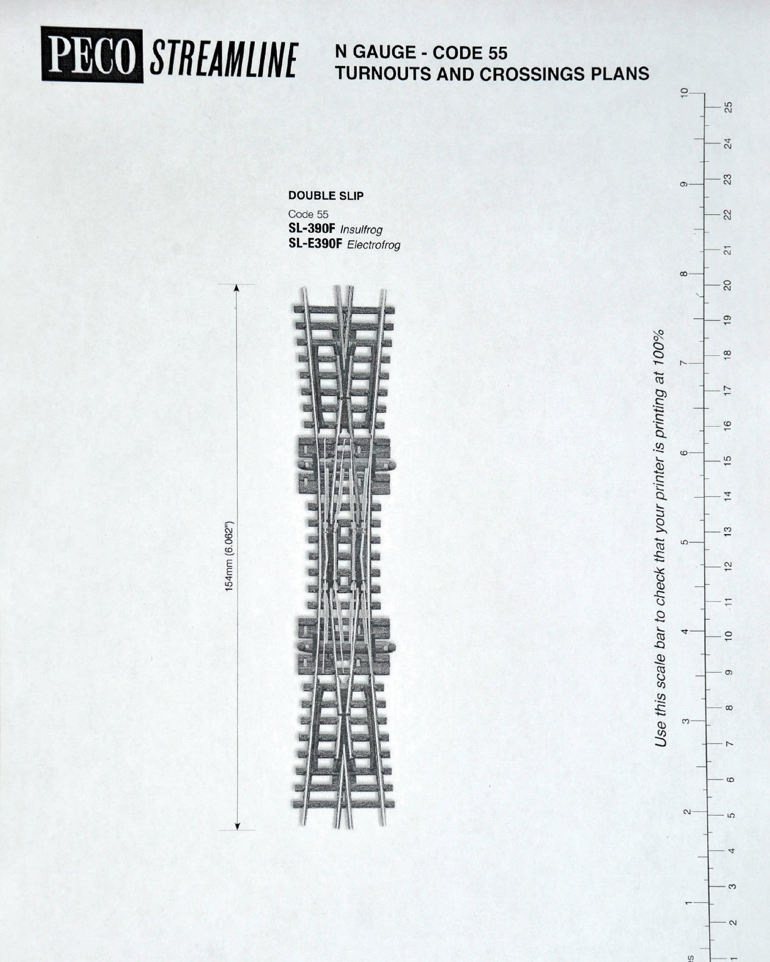
PECO crossover plan.
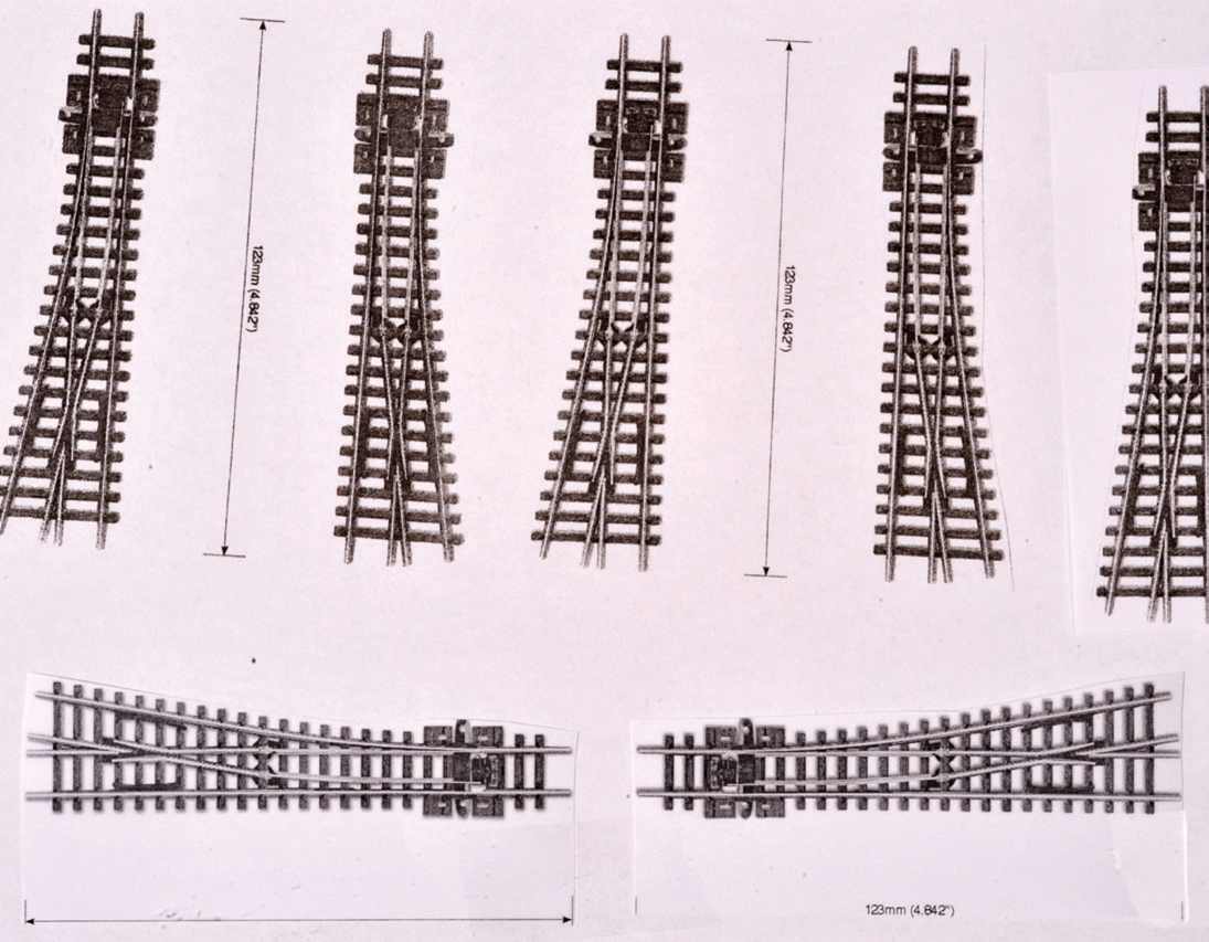
PECO turnout plans.
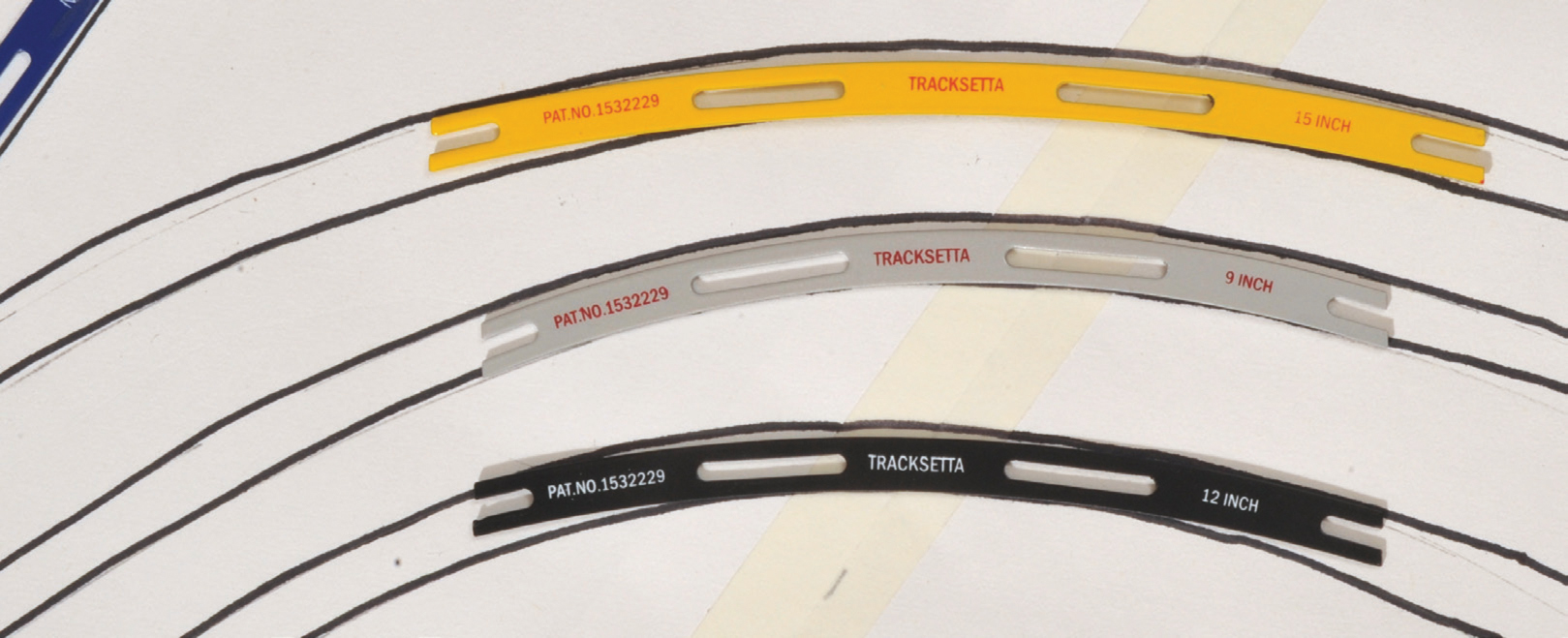
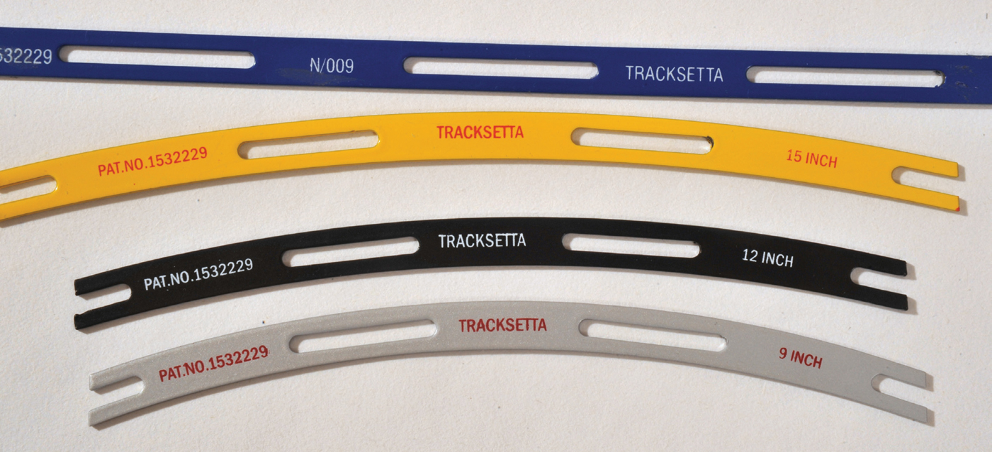
Using Tracksetta gauges to draw track curves.
Once you have what you feel is a satisfactory layout, it is best to attach each printout with a dab of glue – not too much, as you will probably have to adjust the position at least once. When they are all attached, your next move should be to draw in the curves by using the ‘Tracksetta’ templates that PECO, and others, produce. You need to decide on the severity of the curve and its exact positioning, then draw a soft pencil line along each side, finally joining the end with either a point or another curve until you have the full track.
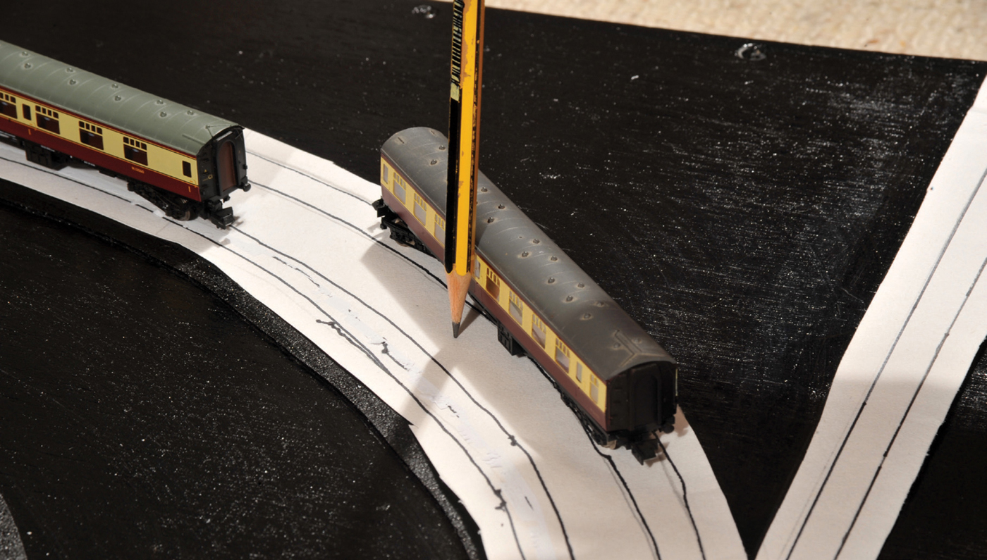
If you are having double, parallel tracks, you need to use a ‘6ft way gauge’ to ensure separation. On tight curves you need to allow a greater space between tracks than a way gauge indicates. To test, line up the two longest coaches on opposite pencil tracks and attach a pencil to the front outer corner and lightly score a line with the pencil. Do the same with the other coach, but with the pencil in the outer middle. There needs to be a gap between the two lines, otherwise the coaches will not pass. The same work needs to be done with platform edges and with buildings and bridges, which is why it is not just the track that has to be planned in detail but also all the buildings.
Only when you are sure that you are happy with the layout should you go over pencil lines with ink.
From this full-scale drawing you will be able to work out your track requirements and, more importantly, the exact sizes of your wood in order to produce a cutting list. Once you have compiled these lists, you can put the plan in a safe place until you have the baseboard completed.
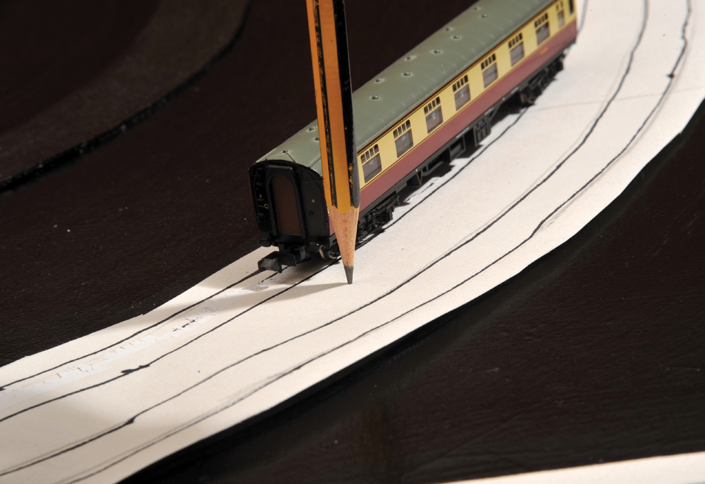
Using a coach to check clearance on a curve – drawing a line following the front corner of a coach when on a curve.
Using a coach to check the clearance on a curve – drawing a line following the centre of a coach when on a curve.
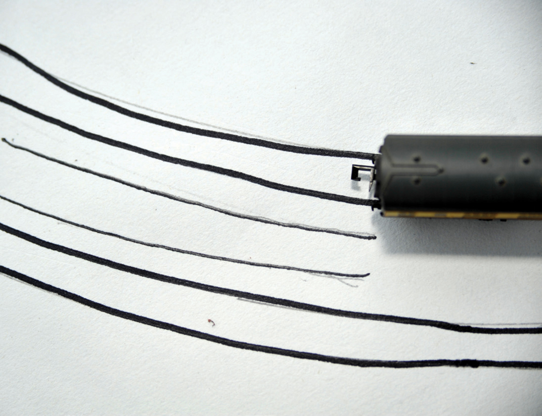
Resulting lines showing clearance of passing coaches.
Later in the book you will find that you need to sketch the layout of the cross-sections on to the baseboard, especially if the cross-members and spine are not 100 per cent symmetrical. Having exactly calculated your track and point requirements, it is probably best to order them as a complete lot and negotiate a discount for the bulk purchase, rather than buying track and points bit by bit.
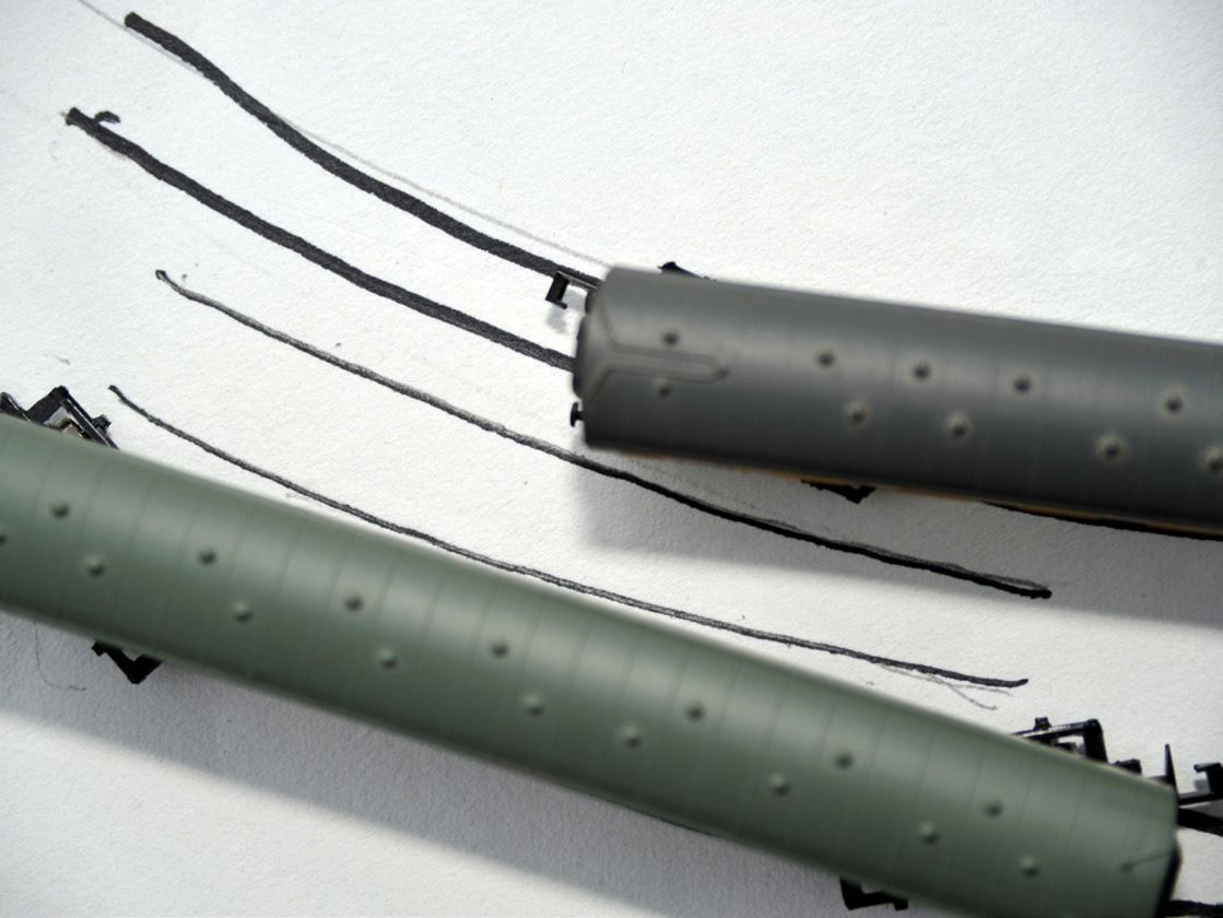
Coaches laid on proposed lines showing clearance on a curve.