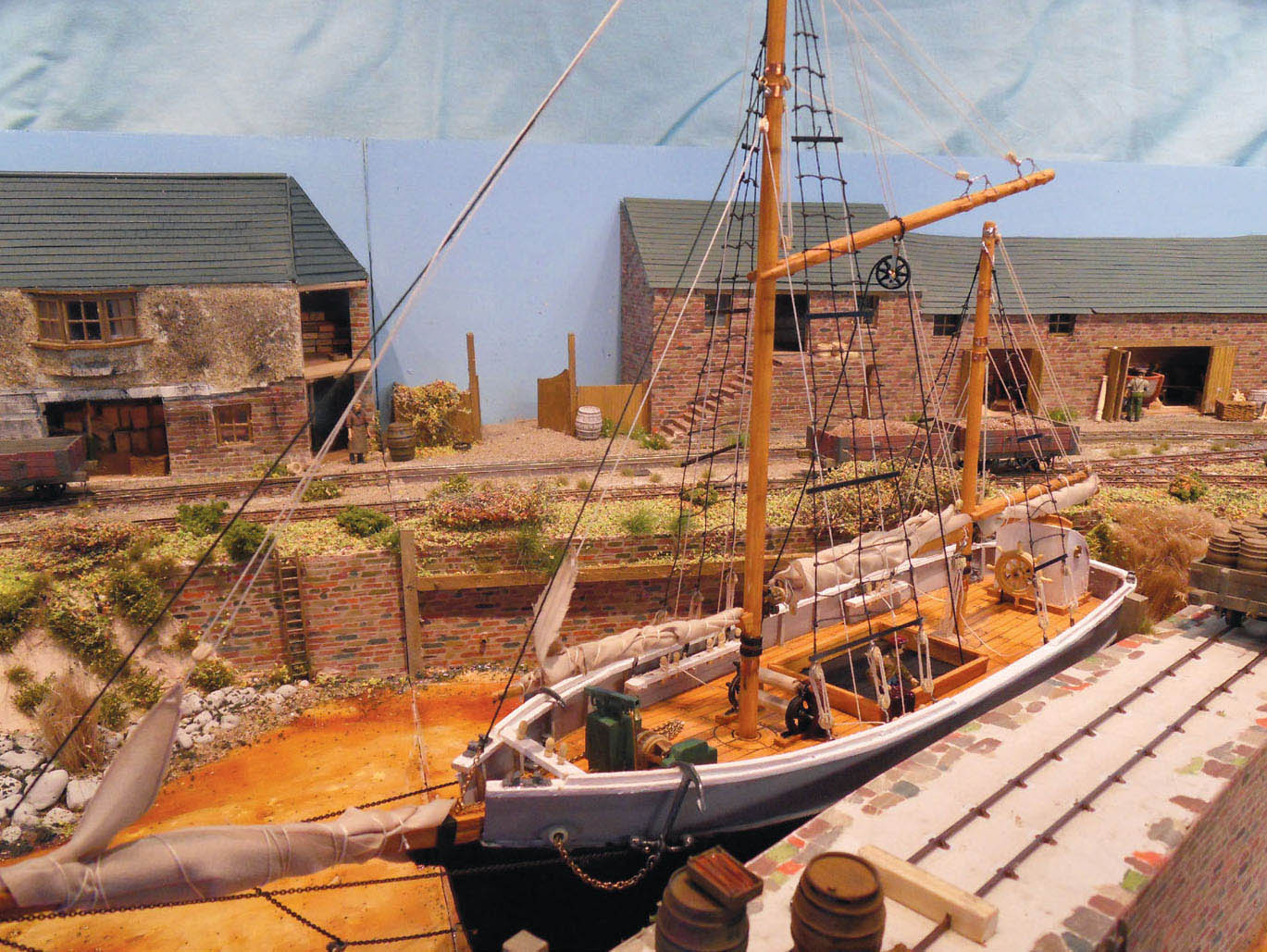
This model is the work of Chris Peacock. Chris has based this delightful narrowgauge layout on Halton Quay on the banks of the River Tamar near to Calstock. CHRIS PEACOCK
PROTOTYPES FOR INTERESTING MODEL PROJECTS
In this chapter I have looked at a few prototypes, and have purposely selected those that would make a good subject for a model railway or diorama. The selection will also give as much variation as possible, illustrating how railways served our ports and inland waterways. However, the prototypes are only used as a base for these models, allowing us to use our imagination and design skills to create a model to fit our requirements. It is a fact that most of us will not have a large room that can be devoted solely to a model railway layout, and we will always certainly have to make compromises to be able to fit a desirable layout into the space that we have available. This will apply to building a layout that connects with and serves a port or inland waterway wharf, especially if we choose the larger scales for our model.
For this reason it is always important that we carefully plan out the layout first, before building anything. Always consider the scale that you will use for your model, and make sure it will ‘fit’ the space available: it is an easy mistake for anyone to make, to have ideas for a model that are too grandiose for the space available, making it an impossible task when it comes to build it. This will only result in disappointment and possibly a complete loss of interest in the hobby.
This model is the work of Chris Peacock. Chris has based this delightful narrowgauge layout on Halton Quay on the banks of the River Tamar near to Calstock. CHRIS PEACOCK
THE LITTLE EATON GANGWAY
The first prototype is an example of one of our earliest railways. Built as a feeder to the canal by Benjamin Outram, the Little Eaton Gangway carried coal and pottery. The 4-mile (6.5km) tramway linked the coal mines around Kilburn and Denby, together with the Denby Potteries, to the trans-shipment point at Little Eaton in Derbyshire. The official name was the Derby Canal Railway, and the canal itself was also built under Outram’s direct supervision. Work started on the gangway in 1793, and was completed in 1795.
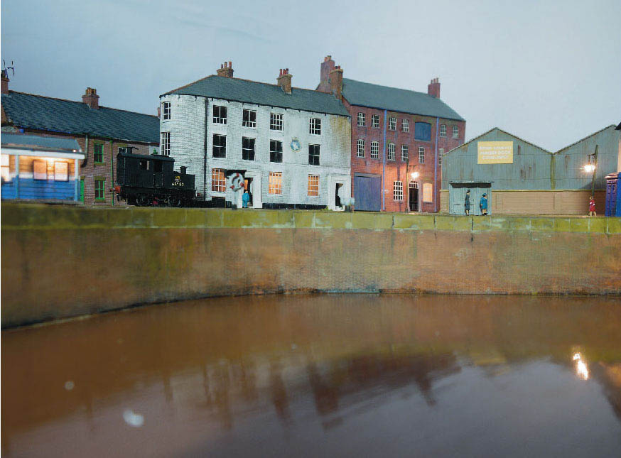
The re-creation of Humber Quay, modelled to perfection by Ian Everett. The line crossing the lock runs along the street as a tramway. The dock carried a wealth of traffic, and this scale four model depicts the scene in the 1950s, with the trains serving the quaysides having to negotiate very sharp curves. IAN EVERETT
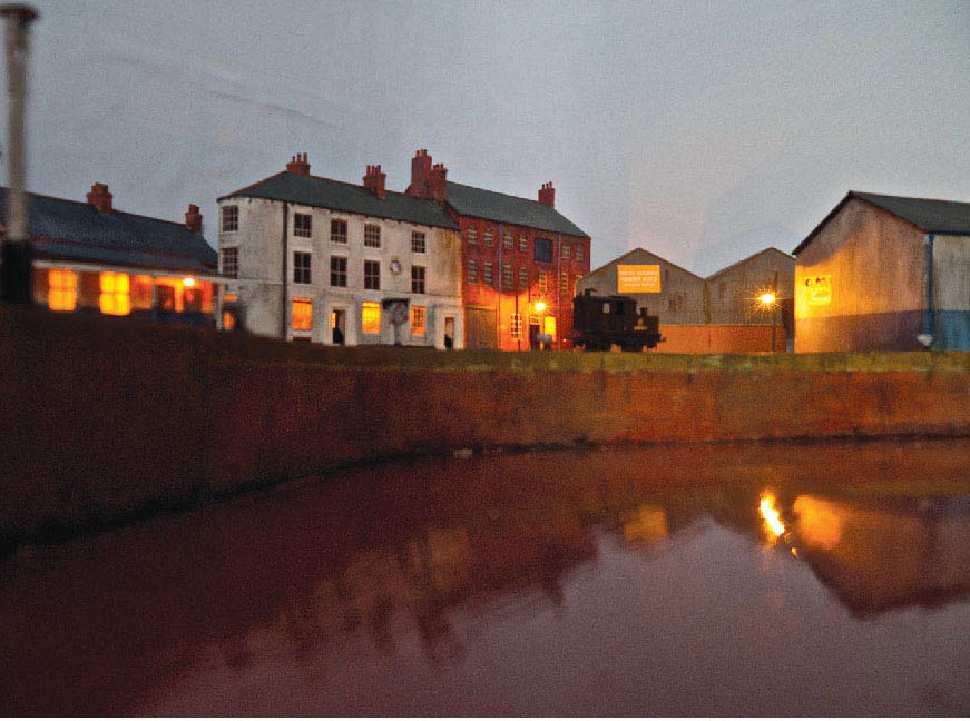
I couldn’t leave out this photograph, showing the same view of the model. This time the house lights have been dimmed, and the model is lit to replicate an evening scene on the dock. IAN EVERETT
The track was originally laid with wooden sleepers, but these were replaced with heavy stone blocks. A train or ‘gang’ of around eight wagons was pulled by four horses walking in single file; they were harnessed together with a gang man leading the first horse. The wagons were fitted with a removable body, which could be lifted, complete with load, by hand cranes, and deposited into the waiting narrowboats. The method of lifting was by a chain sling, making it a primitive forerunner of the modern container system. A preserved example of a Little Eaton Gangway wagon can be found in the collection at the National Railway Museum in York. A good replica wagon has also been put on display in the Mathew Kirtley Museum, which forms part of the Midland Railway Centre.
Most of the line was single track, although the gangway had passing loops along its length. Stud points were used at the passing places and at the sidings in the trans-shipment areas. The route terminated at Smithy Houses and Denby Hall Colliery at the north end, with branches leading to Salterwood North Colliery, Henmoor Colliery and the Denby Pottery Works. The southern end formed a terminus with the Derby Canal at Little Eaton. The rails were made from L-shaped iron with a shallow curve to the top edge.
The gangway lost most of its trade when the Midland Railway opened its branch line to Ripley, and was finally closed in 1908. Most of the track bed has now completely gone, although there are a few traces left if you know where to look.
CREATING A MODEL
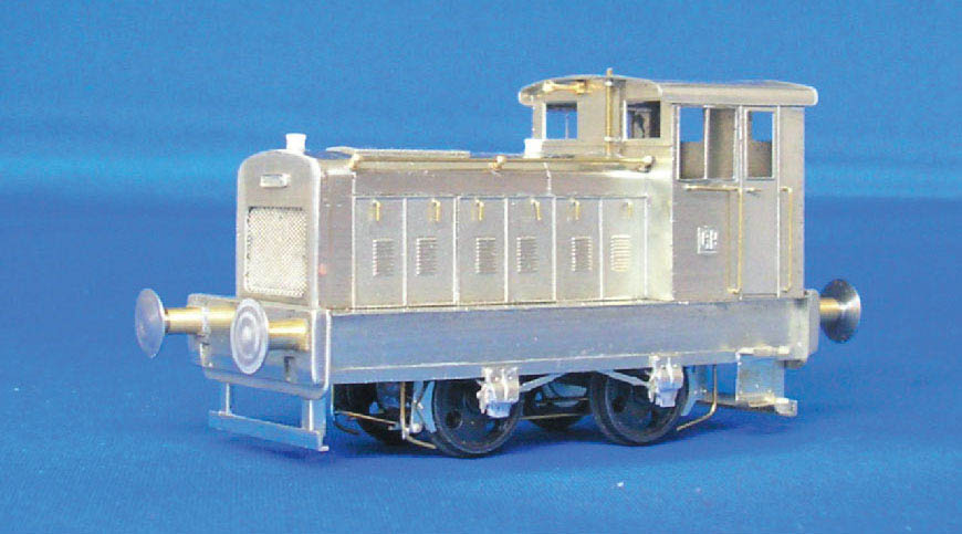
For those wishing to model the Little Eaton Gangway I would suggest constructing a diorama rather than a layout. The track would have to be scratch-built along with the wagons, and of course the gangway employed horses to pull the wagon trains. The alternative would be to use ‘modeller’s licence’ and model the wharf re-laid with standard- or narrowgauge track and point work. Locomotives could also be introduced, but I would advise looking at the small short-wheel-based classes. The small quarry ‘Hunslet’ would be ideal if you choose a narrow-gauge option, and the Johnson Midland ‘Burton Tank’ would perhaps suit the standard-gauge choice. There are kits available for these classes, although they tend to be for the 7mm market. EDM Models produce a few variants of the narrow-gauge Hunslet, and the ‘Burton Tank’ was produced by Eric Underhill.
Another alternative for a small, standard-gauge locomotive would be the Hudswell Clarke 0-4-0 ST from the Agenoria ‘0’ Models range. Agenoria also now produce a kit of an early cauldron wagon, which would suit this industrial wharf diorama perfectly.

A three-dimensional view of the curved holding sidings at the wharf, together with a track plan to show the transhipment part of the wharf with the Derby Canal. A) transhipment shed B) storage sheds and workshops C) the New Inn public house D) weighbridge E) loading cranes.

A full size replica of one of the wagons used on the Little Eaton Tramway. The wooden body of this wagon could be lifted complete with load from the wheels, making this an early example of the container transportation used today. The replica wagon forms part of the historical collection in the Mathew Kirtley Exhibition Hall at the Midland Railway Centre.

Another view of the same wagon; this is a very good replica, while the original still exists in the National Railway Museum at York.
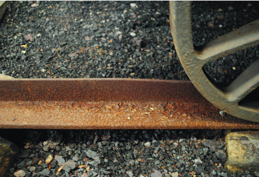
In this close-up photograph I have concentrated on showing the type of iron rail used by Outram for the Little Eaton Tramway. The rails were originally laid on wooden block sleepers, but these were soon replaced by the ones made from stone.
THE LIVERPOOL OVERHEAD RAILWAY
For this prototype I have chosen an unusual railway built to give passengers direct access to the docks at Liverpool. By the late nineteenth century the larger ports around the country had grown to accommodate the requirement of trans-shipping all kinds of goods as well as passengers. Liverpool, due to its position, became England’s premier port, and by the 1880s the dock network was virtually complete. However, the congestion that resulted required the dock board to look at an alternative transport system to move passengers.
Two leading engineers, Sir Douglas Fox and James Henry Greathead, were commissioned to design a railway system, with work commencing in October 1889. It was decided that the motive power for this railway would be electric traction. Steam was considered too dangerous, owing to the many flammable cargoes: the locomotive sparks could easily ignite any goods that were in close proximity. Electric traction also had other favourable advantages such as speed, quiet running and cleanliness, besides being economic to run.
The Liverpool Overhead was the world’s first elevated electric railway. It was completed in 1893 and the line stretched right along the waterfront to serve all the major docks. Public services began and terminated at Alexandra Dock in the north, with intermediate stations serving Brocklebank, Canada, Sandon, Clarence, Princes, Pier Head, James Street, Custom House, Wapping, Brunswick and finally Toxteth.
The line was extended to tap the trade from the more residential areas, and a short extension was opened in 1894 to Seaforth on the northern end. A year later a much more ambitious extension was made by spanning the Cheshire Lines goods yard with a lattice girder bridge and then boring a half-mile tunnel. The line terminated with an underground station built at Dingle, opened in 1896. The overhead railway was successful and provided a good service, at the same time giving wonderful views of the visiting ships and the docks. The railway’s passengers consisted of those who were joining the passenger liners, and those who just wanted to see the sights – and of course the dockers used the railway as a means of getting to and from work.
The railway was hit during the blitz in World War II, and suffered severe bomb damage. However, this was soon repaired and the railway operated until the mid-1950s, when it was reported that the decking plates were decaying and needed to be replaced. With the cost of replacements estimated at two million pounds, it was decided that the Liverpool Overhead would close the following year, and on 30 December 1956, despite public protest, this is what happened. It wasn’t long before the demolition crews were sent in, and this well loved and pioneering railway was totally removed.
The Liverpool Overhead paved the way for other similar systems around the world, including those in the major American cities, and over the last few decades we have seen new rapid rail systems using a similar format. The railway is now a distant memory, but the ‘Dockers’ Umbrella’ will never be forgotten. A section of the elevated structure, along with one of the early electric cars, is displayed in the new Museum of Liverpool.
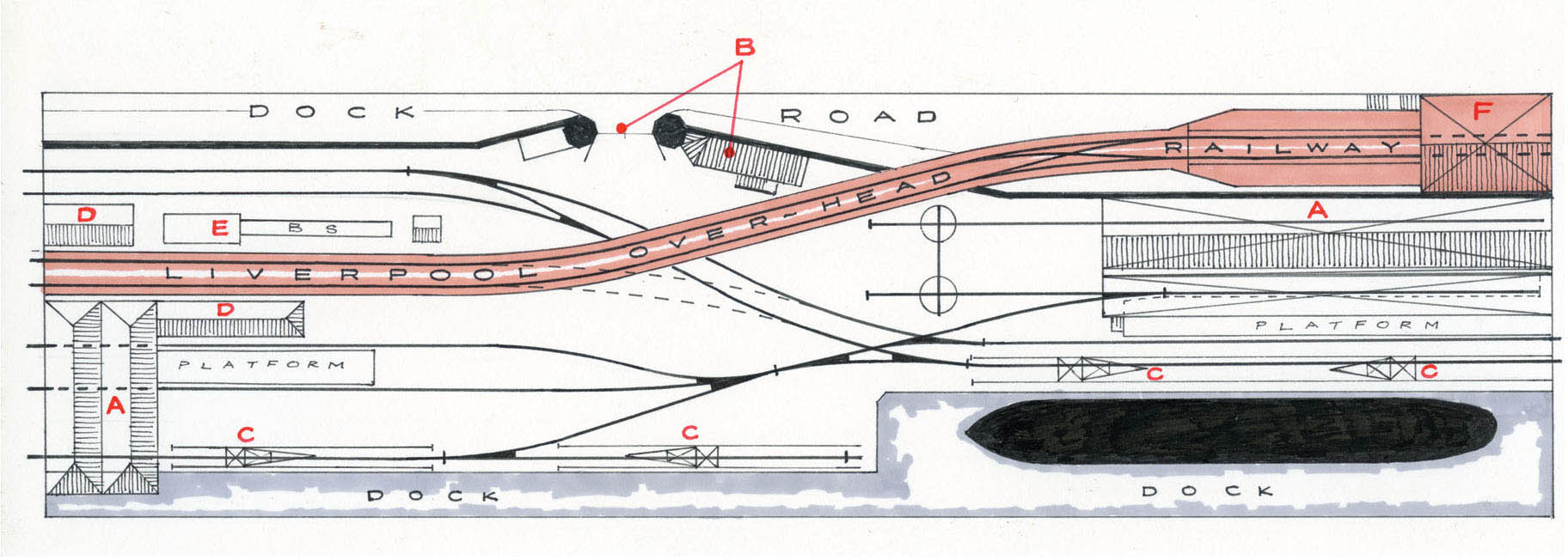
An imaginary track plan based on a section of the Liverpool Overhead Railway. The layout is divided into two levels, with the LOR above and the Mersey Docks & Harbour Boards railway at ground level, re-creating a miniature replication of the ‘Dockers’ Umbrella’. A) warehouses and trans-shipment sheds B) dock gates and office C) travelling cranes D) stores E) office and bike sheds F) station and train shed.
LAYOUT BASED ON THE LIVERPOOL OVERHEAD RAILWAY
The layout plan for this book has been based on Liverpool’s Overhead Railway, although I have purposely designed it to include part of the Docklands Railway that served the many docks along Liverpool’s waterfront. The Overhead Railway runs the full length of the baseboards, elevated all the way. I have included a station at the rear with the usual overall roof, which provides a mask for the tracks to run off the visual part of the layout. The run-off at the other end is masked by a large warehouse positioned in front. The Dockland Railway of the Mersey Docks & Harbour Board also runs the length of the baseboard, but at ground level. This required tracks running off to separate fiddle yards from the overhead section. The same large warehouse masks the tracks where they disappear off the visual boards. The front of the layout is completely dominated by the docks, with tracks running along all the quaysides. Some of the tracks also run into the warehouses for sheltered loading and unloading.
You need to run authentic electric stock for the overhead section, which is now available in 4mm scale from Judith Edge Kits. Both the original wooden body and the later rebuilt ‘all-steel’ stock have been produced.

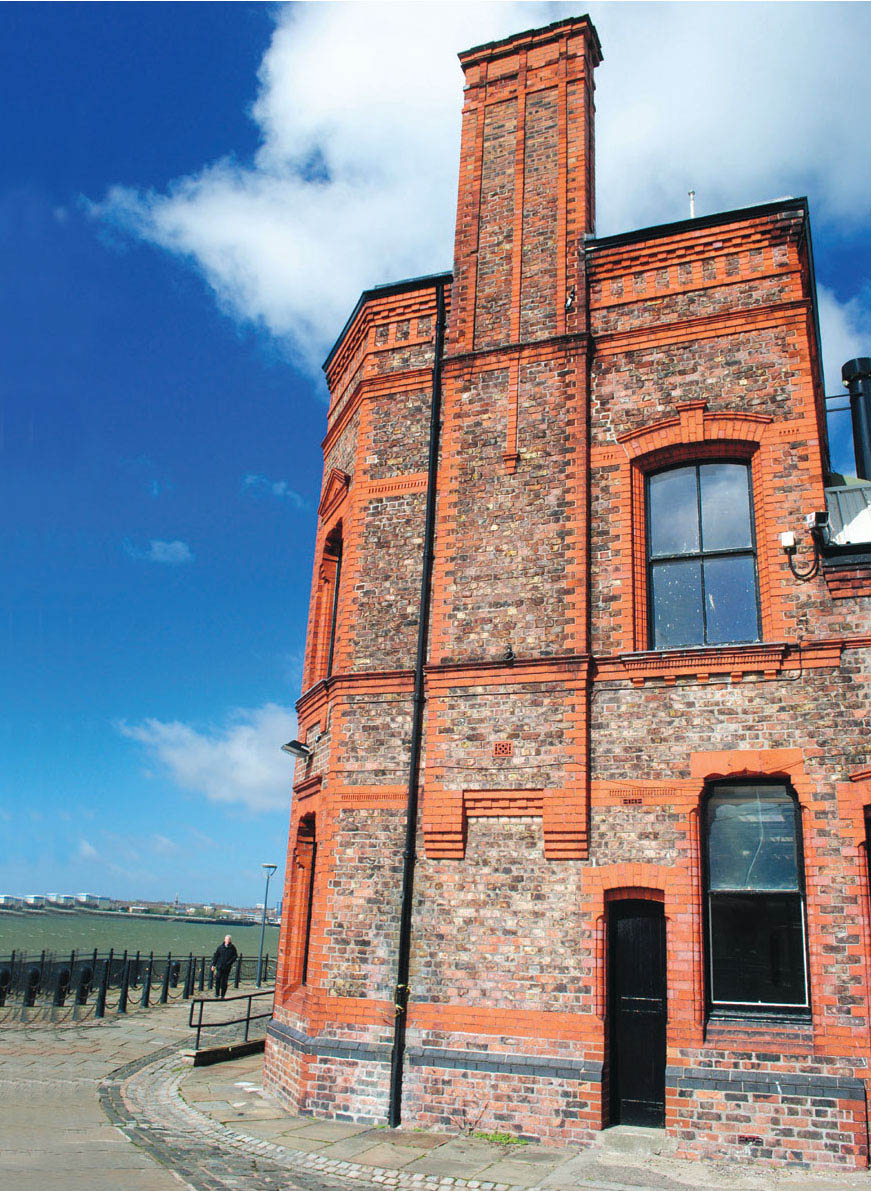
One of the hydraulic engine houses that provide power for opening and shutting the lock gates in the docks. This building could also be included on the layout to make an interesting feature.
The harbour and customs offices fronting the River Mersey, guarding the locks and entrance to the docks from the river.
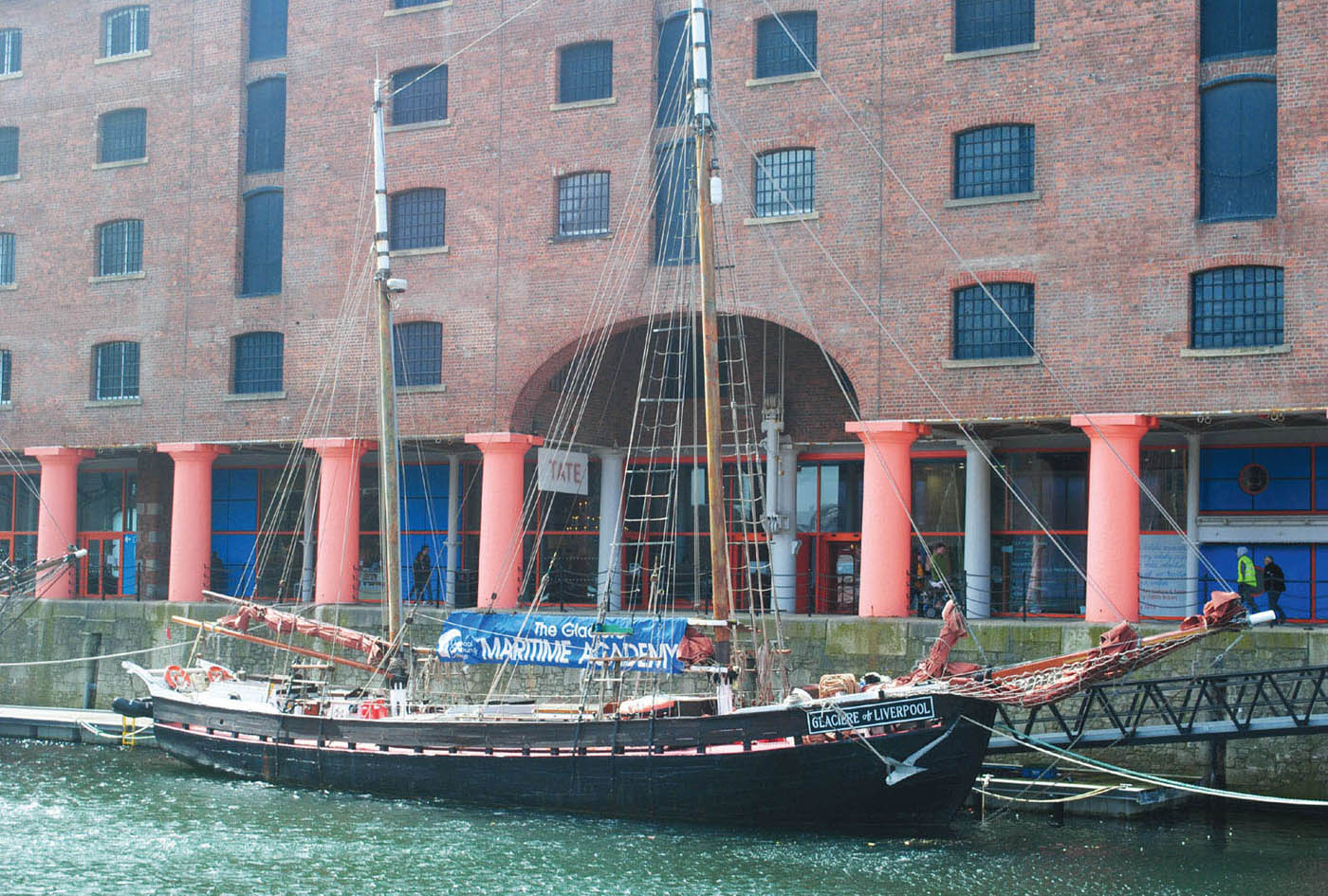
The distinctive architecture of one of the large warehouses fronting the dockside of Liverpool’s Albert Dock.
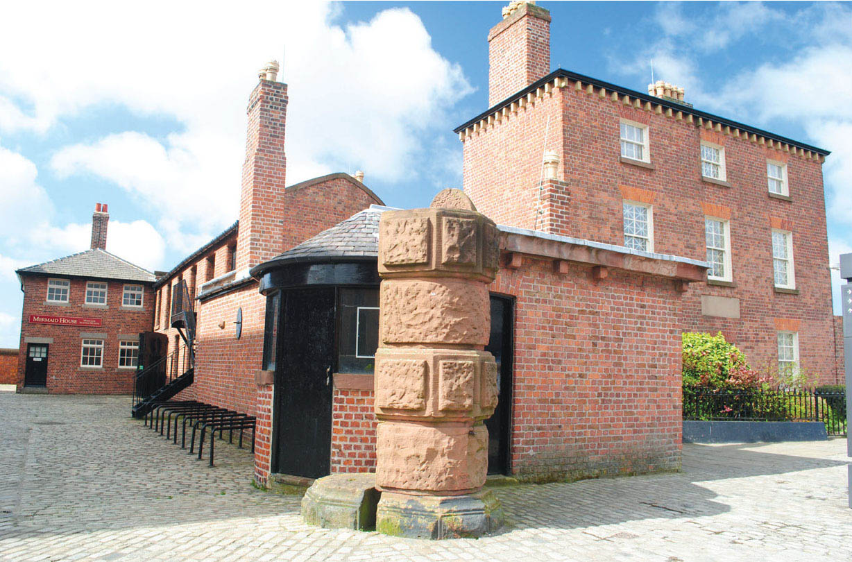
One of the gateways into the docks, together with the associated buildings. One of the street gates is featured in the layout plan.

This general wide view of Albert Dock gives an idea of the scale.
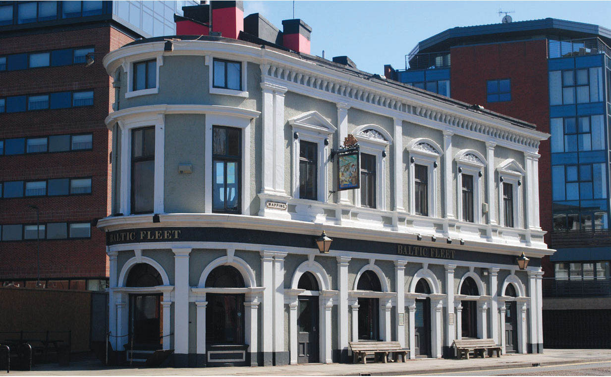
The ‘Baltic Fleet’ is one of many public houses found along Dock Road. The pubs would have been frequented by dockers needing well earned refreshment after a busy shift in the docks. The pub would also make an extra addition to the model – though if it was included, reproducing some of the architectural embellishments in miniature would be challenging.
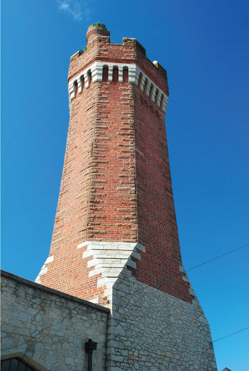
This interesting brick structure was photographed along the dock wall. I am not sure of its use – it could it be a chimney or perhaps an air shaft. A reader of this book can possibly answer the question, but whatever it is, it would be included on the model.

The large block of warehouses fronting Wapping Dock. These have now been transformed into private apartments, but have not lost any of their original architectural splendour. All the renovated dock buildings at Liverpool have been done sympathetically, restoring their original charm.

Another view of one of the office buildings situated around the dock gates. This close-up image gives more detail reference for the modeller.
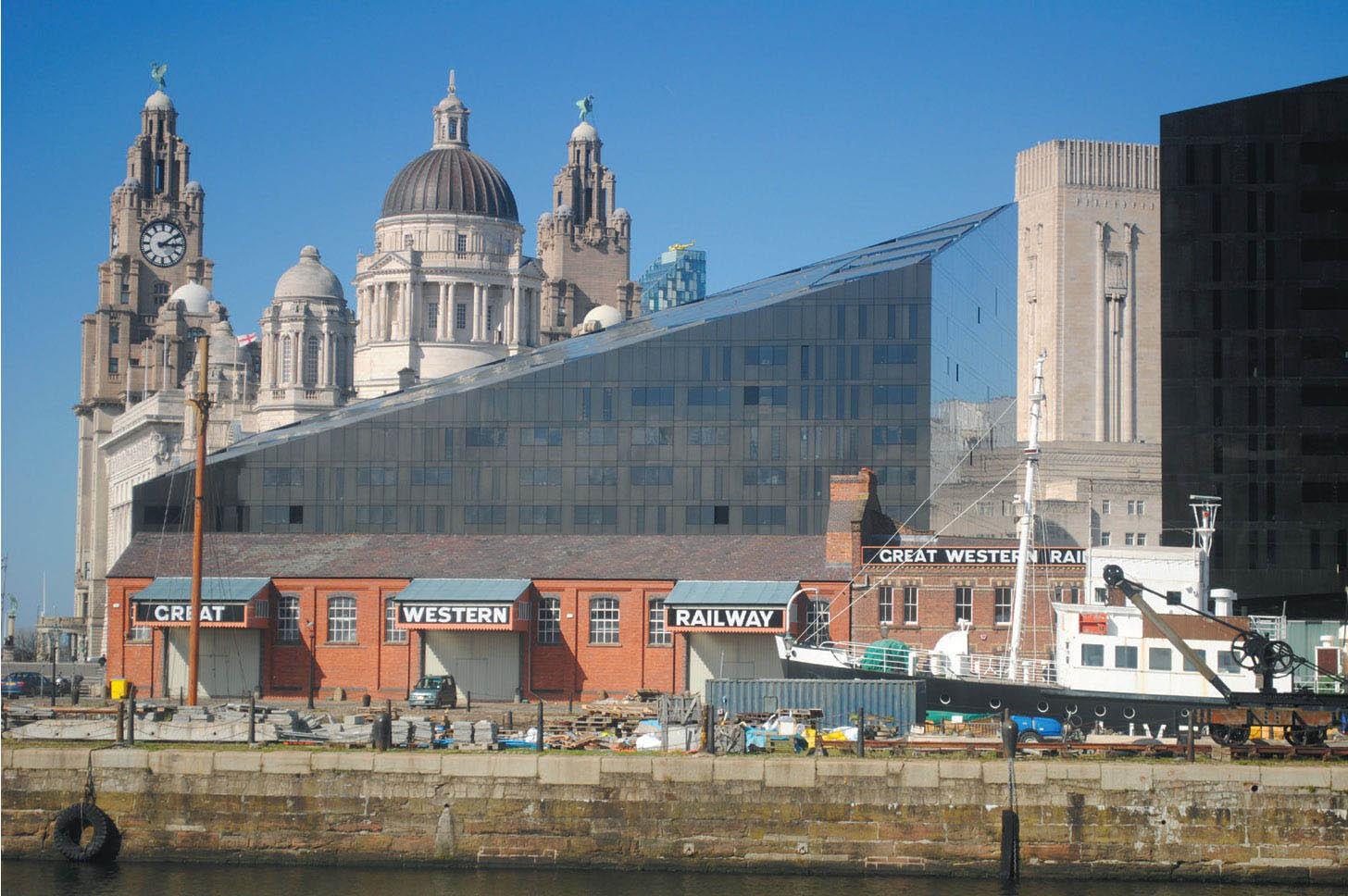
The modern glass and steel offices and hotels sit side by side with the older majestic buildings on Liverpool’s waterfront. I will leave it to your opinion as to whether the ultra-modern does gel with the ‘Three Graces’ dominating the background!
On the docklands section, ready-to-run shortwheelbase locomotives such as the ex-Lancashire & Yorkshire ‘Pug’ from Hornby would be ideal. Other dock tanks would also fit the layout, but these would need to be built from kits. Judith Edge Kits also produce a range of industrial steam and diesel locomotives that are authentic to the Mersey Docks & Harbour Board Railway; you would need a good number of wagons, as this part of the layout consists of just goods vehicles. There are plenty of ready-to-run samples or kits that would suit the requirements of this layout.
Besides the locomotives and rolling stock, Judith Edge Kits are producing etches for the elevated sections of track, giving the modeller the perfect opportunity to create this unique railway system in miniature.
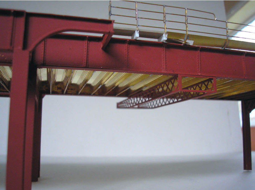
One section of the overhead structure. This 50ft (15m) span is now available in kit form, together with other special components and station girders from Judith Edge Kits. MIKE EDGE

Sections of the overhead spans have been put together to show a good length of the structure. MIKE EDGE

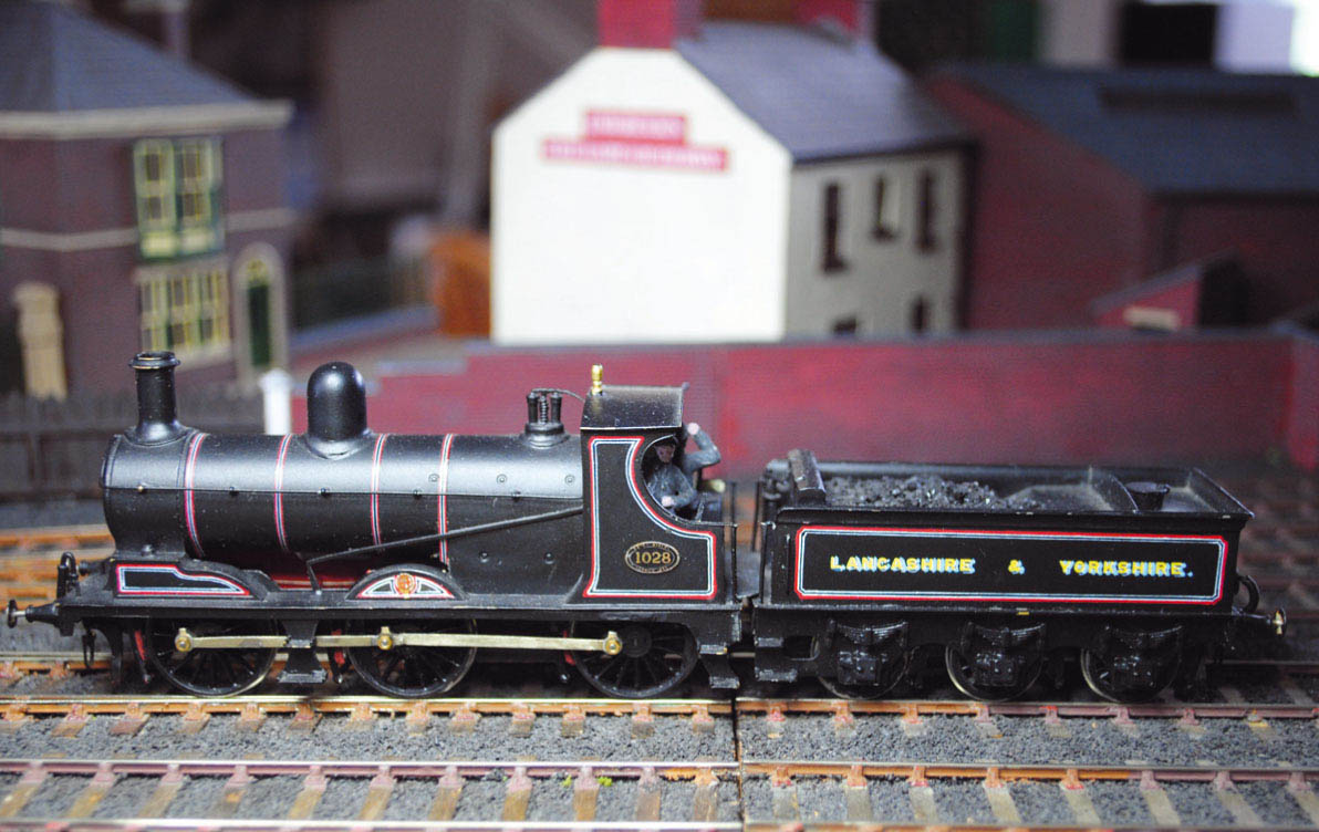
One of the Lancashire & Yorkshire Railway’s 0-4-0 ‘Pugs’. This class of locomotive would have worked the dock railways for many years, and would be well worth including on any model.
Part of Mike Edge’s layout of ‘Herculaneum’, based on the prototype at the eastern end of the docks. MIKE EDGE
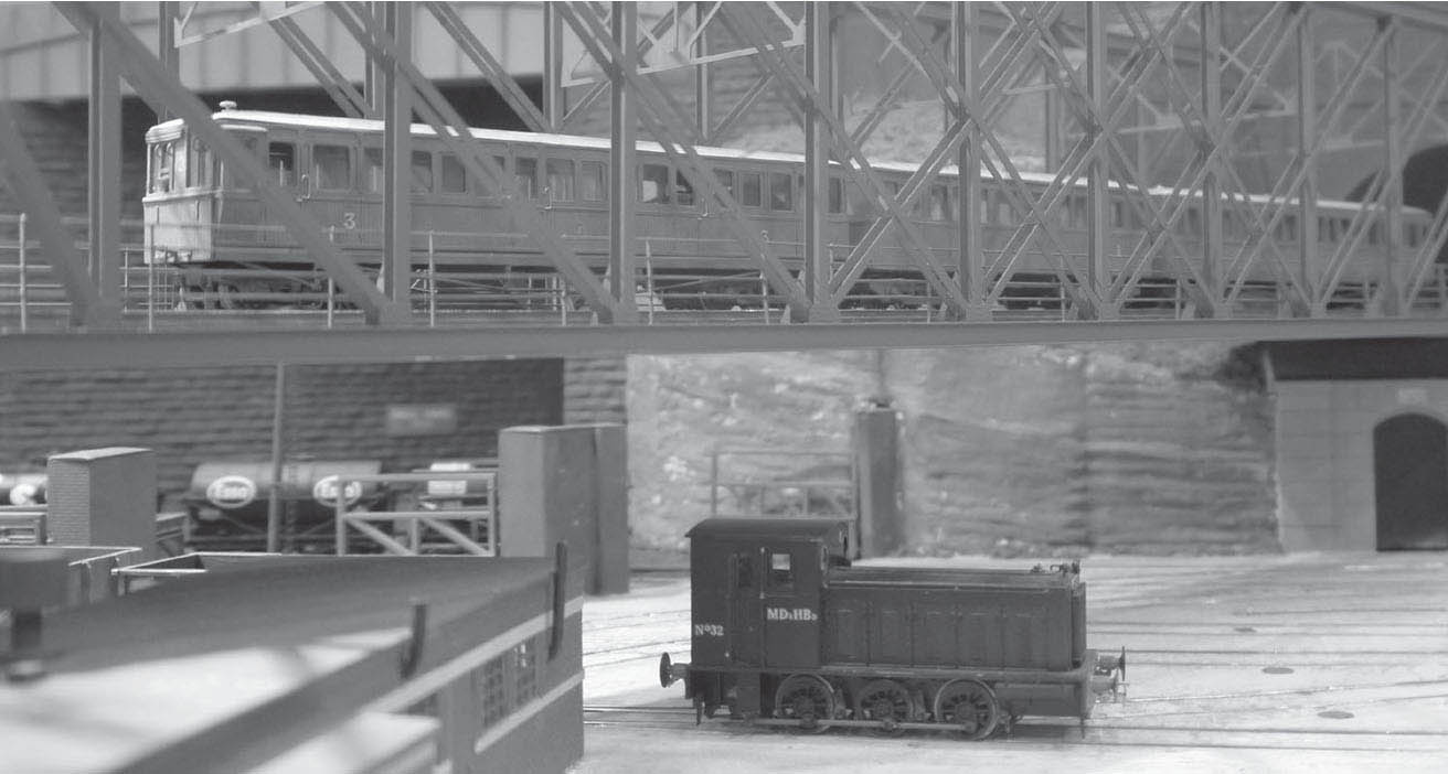
This view of Mike’s splendid layout shows the Liverpool Overhead Railway crossing the Cheshire Committee Lines extension into Herculaneum Dock on the impressive 200ft (60m) long lattice girder bridge, before diving into the tunnel cut through the sandstone rock to reach its eastern underground terminus station at Dingle. MIKE EDGE
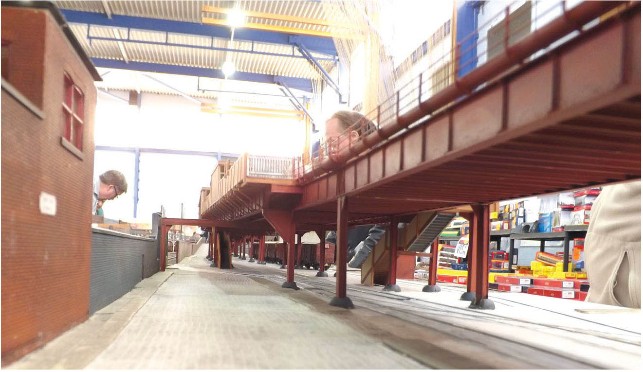
The overhead structure in position on Mike Edge’s layout. The low angle gives a good impression in miniature of the structure as seen from street level. MIKE EDGE

The 4mm kit provided by Judith Edge Kits of the early woodenbodied Liverpool Overhead Railway electric sets. MIKE EDGE

The Judith Edge kit of the later all steel-bodied electric units. MIKE EDGE
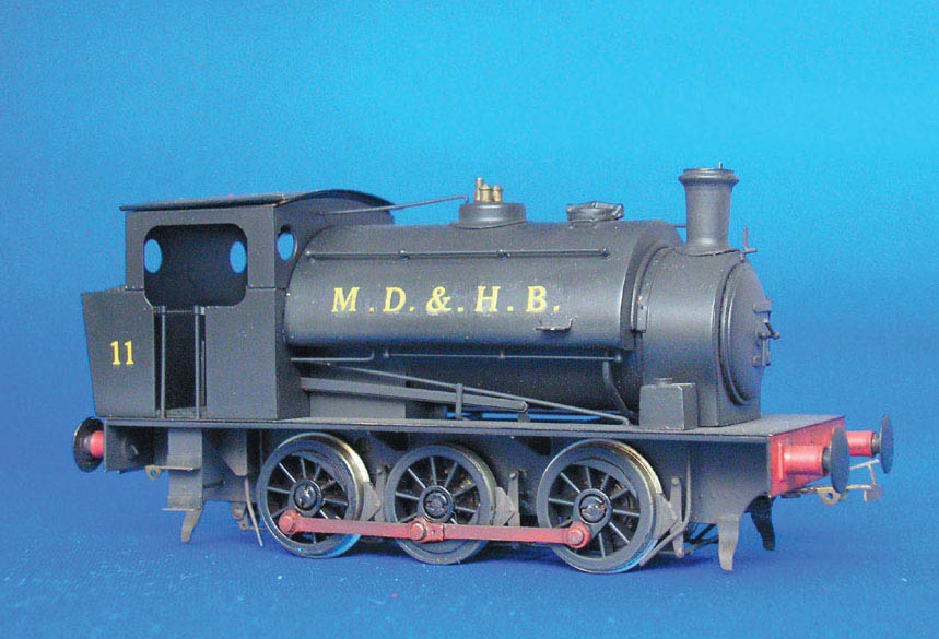
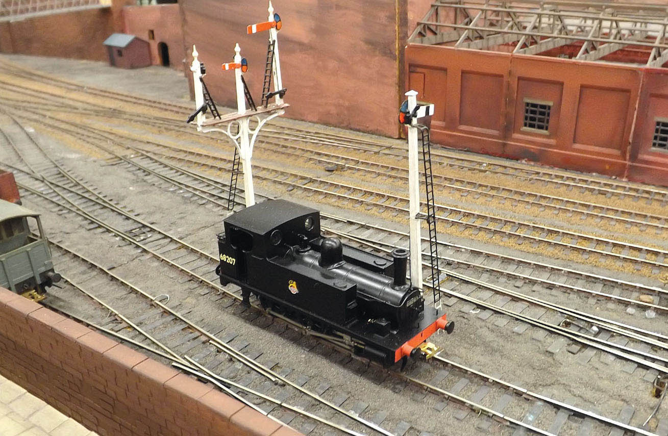
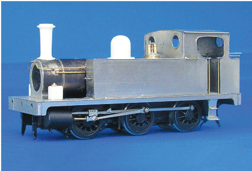
This model from Judith Edge Kits shows the Hunslet 15in 0-6-0 Saddle Tank locomotive No. 11 in the Mersey Docks & Harbour Board black livery. MIKE EDGE

This model of the Hunslet Saddle Tank No. 31 is depicted in the MD & HB green livery. MIKE EDGE
The Judith Edge kit of the LNER class J63 (ex-Great Central Railway 5a) 0-6-0 Tank locomotive under construction. This class of loco would have worked certain sections of the docks. MIKE EDGE
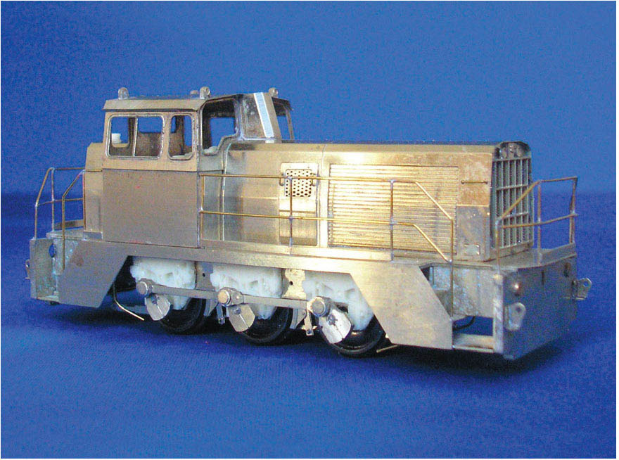
The Hunslet 325hp 50T 0-6-0 Diesel Hydraulic locomotive produced by Judith Edge Kits. MIKE EDGE
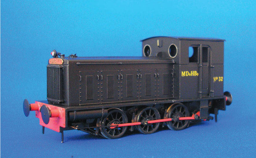
The kit of the Hunslet 204hp 0-6-0 Diesel Hydraulic locomotive. These would have also worked the docks in later years. It is depicted here in the MD & HB black livery as No. 32. MIKE EDGE
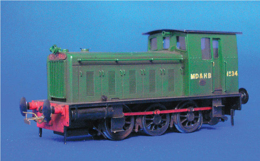
Another Hunslet, this time a Diesel Mechanical 0-6-0 No. 34; it is depicted in the green livery of the MD & HB. MIKE EDGE
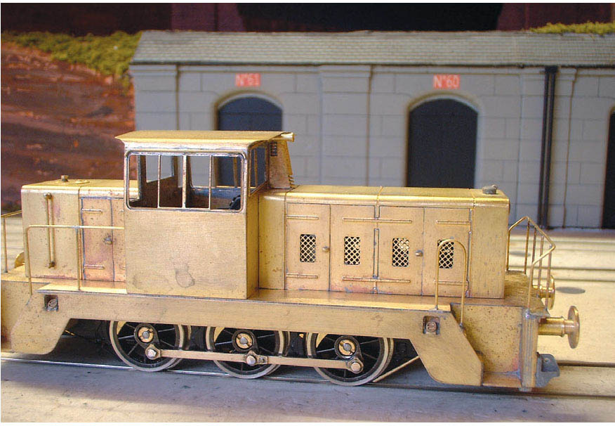
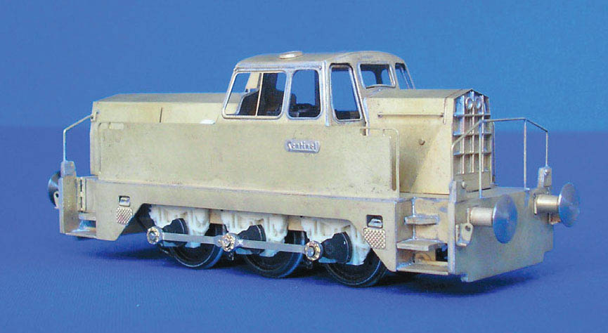
This kit of the Sentinal 0-4-0 Diesel Hydraulic shows the locomotive with rod drive, rather than chain driven. Like the Hunslets, these diesels would also have seen active service within the confines of the docks in later years. MIKE EDGE
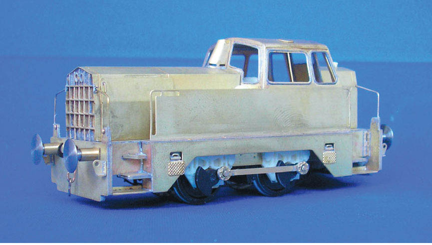
The larger Sentinal 0-6-0 Diesel Hydraulic. The larger-wheel-based locomotives would have been restricted to those areas of the docks with less severe curves. MIKE EDGE
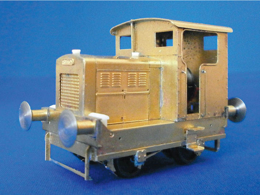
The short-wheel-based kit of the Rushton DS 0-4-0 Diesel Mechanical. MIKE EDGE
The kit of the Thomas Hill Vanguard 0-6-0 Diesel Hydraulic. These diesels may also have seen active service within the dock system. MIKE EDGE
Another Rushton short-wheel-based 0-4-0 Diesel Mechanical, also available from Judith Edge Kits. MIKE EDGE
In complete contrast to the previous prototype, this railway was built to carry just mineral traffic and occasionally timber. The Portreath branch was constructed by the Hayle Railway Company in 1838. A better transportation system was needed to move the rich copper ore from the mines around the towns of Redruth and Camborne, in West Cornwall; it had to be shipped across to South Wales for smelting, so the line needed to connect with the harbour of Portreath on the north Cornish coast. The inward traffic was also from South Wales, with coal the main import but also timber to be used as props in the mines. The line for the most part was level, though to reach sea level at Portreath it had to drop down the hillside on an incline of 1 in 10.
The branch line was constructed by the Hayle Company to serve Portreath Harbour at the time when the copper mines were at their peak. This, however, was to become short-lived as the copper market became flooded from other parts of the world, producing a slump in the demand for copper from Cornwall. The mines never recovered from this and the importance of Portreath as a coastal port soon declined. The port remained open for the importing of the South Wales coal, which was still required for local industry and household use, but due to the narrow confines of the approaches and entrance to the harbour it was difficult to encourage any new trade. The harbour still remained open, with cargo vessels using it until 1960.
The railway was taken over by the West Cornwall Railway in 1846 and then amalgamated into the Great Western Railway in February 1876. The railway employed steam locomotives on the level section of the line based at Carn Brea. The 0-6-0 saddle tanks became the common motive power used on all the mineral trains, although later, 0-6-0 pannier tanks took over this duty. The engine shed at Carn Brea, including a workshop, closed along with the shed in 1917. After this date locomotives working on the branch were stabled at Truro, which remained the norm until final closure of the line in January 1936.
The route of the branch commenced from Carn Brea yard, curving away from the mainline sharply, before continuing straight to the road crossing on the Illogan highway (now the A30). At this location the line also crossed the Camborne & Redruth Tramway, a 3ft 6in-gauge track that ran alongside the road. It opened in 1902 to convey ore from East Pool and Wheal Agar mines.
The line continued to North Pool, before traversing Illogan Downs on a low embankment. It then crossed two level crossings, one with the novel name of ‘Lovely Cottage level crossing’, and the other ‘Fairfield crossing’. Beyond the crossing the branch continued towards the Portreath incline, and just before the engine house the line doubled for the complete length of the incline. A release crossover was provided, this being the limit for the locomotives on the branch.
Close to the engine house stood a cluster of buildings including the engine operator’s house and the stable for the horses employed for shunting. An interesting round, stone-built cabin was positioned alongside where the descent of the incline started. The incline ran through a granite cutting before ending on a stone-built embankment. Positioned right at the bottom was the station master’s office, the mess room, the stores and the stables. A pair of gates over the Redruth road also provided an entrance to the harbour yard. The southern side was accessed by a pair of turntables right at the bottom of the incline positioned just before the gates. Just over the road the two lines converged with another wagon turntable providing access to the northern side of the docks.
The majority of the harbour sidings were situated on the southern side to the harbour served by the two turntables. A wagon weighbridge with office alongside was positioned at the throat of the sidings. These sidings gave access to the dock basins where extensive coal dumps were situated. The sidings were quite extensive, until being rationalized around the 1890s. This came about due to the demise of the Poldice tramway.
The harbour at Portreath originally dated from 1760 with the construction of the pier. At the same time a mule track was built to serve the mines in the Gwennap area to the south-east of Redruth. General improvements were made by 1809, when a tramway was constructed to convey ore from the mines at Poldice to the pier at Portreath. The first rail was laid by Lord de Dunstaville, making the ‘Portreath & Poldice Mines Plateway’ the first tramway in Cornwall. This was originally laid to 3ft gauge, using the ‘L’ section of cast-iron plates fixed to granite stone blocks. This tramway became redundant, although the Portreath section was assured in 1838 with the arrival of the Hayle Railway.
Eight years later, work began on the construction of the inner basin with a capacity to take ten vessels of the type and size trading at this time in and out of Portreath, and the railway was used for the transportation of materials for its construction. A modification was made to the pier, with a protective barrier being installed to cope with the heavy seas. The last major development was the construction in the late 1860s of the basin in the south-west corner of the site. It was known as the ‘new dock’, and included a slipway as well as additional mooring. The dock regularly served as a turning facility for the ships manoeuvring within the harbour.
The harbour was owned by the Bain family, and David Wise Bain was the harbour master. Bain built up a considerable fleet of sailing ships trading in general cargoes. The sailing ships were soon replaced with steam-powered vessels. The steam ship fleet included Guardian, Treleigh, Panmure, Plover and Olivia. The single tall funnels carried a large letter ‘B’, and this became a familiar sight in the harbour. In 1866 Portreath was made a free port, when the depression had more or less seen the total collapse of the local copper industry. In 1888 a steam tug was introduced to assist the ships entering the tight harbour. Around the same time steam cranes were also installed; these ran on standard-gauge rails positioned along the quaysides.
Portreath capitalized on the landing of pilchards, for which Cornwall became renowned during the autumn months when large shoals came into the inshore waters. This of course resulted in a welcome source of revenue, but it was not to last, and the trade had largely disappeared by the turn of the century.
The harbour also featured a lime kiln, situated on the south side of the site. The burning of limestone produced lime for both local agriculture and building work. The limestone was shipped in from Plymouth and over the channel from South Wales. The kiln remained in use until the 1950s, and was finally demolished in 1967.
On the south side of the harbour was a large building originally built for the fishing trade and known locally as the ‘Fish Palace’. It was also used for the construction of sailing ships by shipwright Thomas Massey. The branch would have transported materials used for the ship-building trade.

A track plan for Portreath Harbour, condensed to make a layout that fits into a more reasonable space. The layout also assumes that locomotives worked the harbour site, so I have included an engine shed together with servicing facilities. A) cottages B) engine shed and coaling stage C) stable block D) coal merchant’s offices E) coal heaps F) shelters G) look-out cabin.
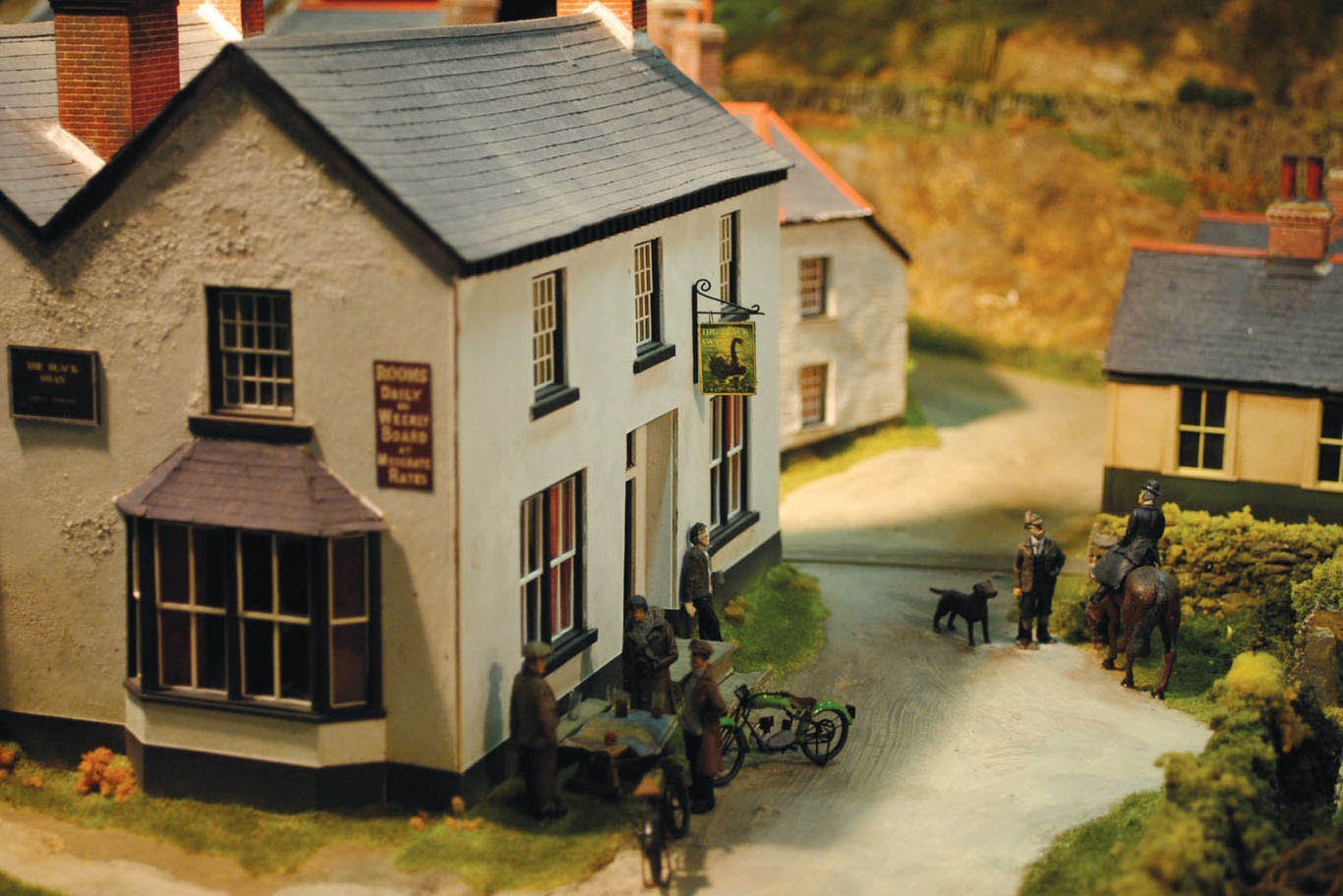
I photographed this charming model of a Cornish pub while visiting ‘RAILEX 2014’. It is the work of the Helston & Falmouth MRG. This building displays typical Cornish style, and would not look out of place on the Portreath layout.
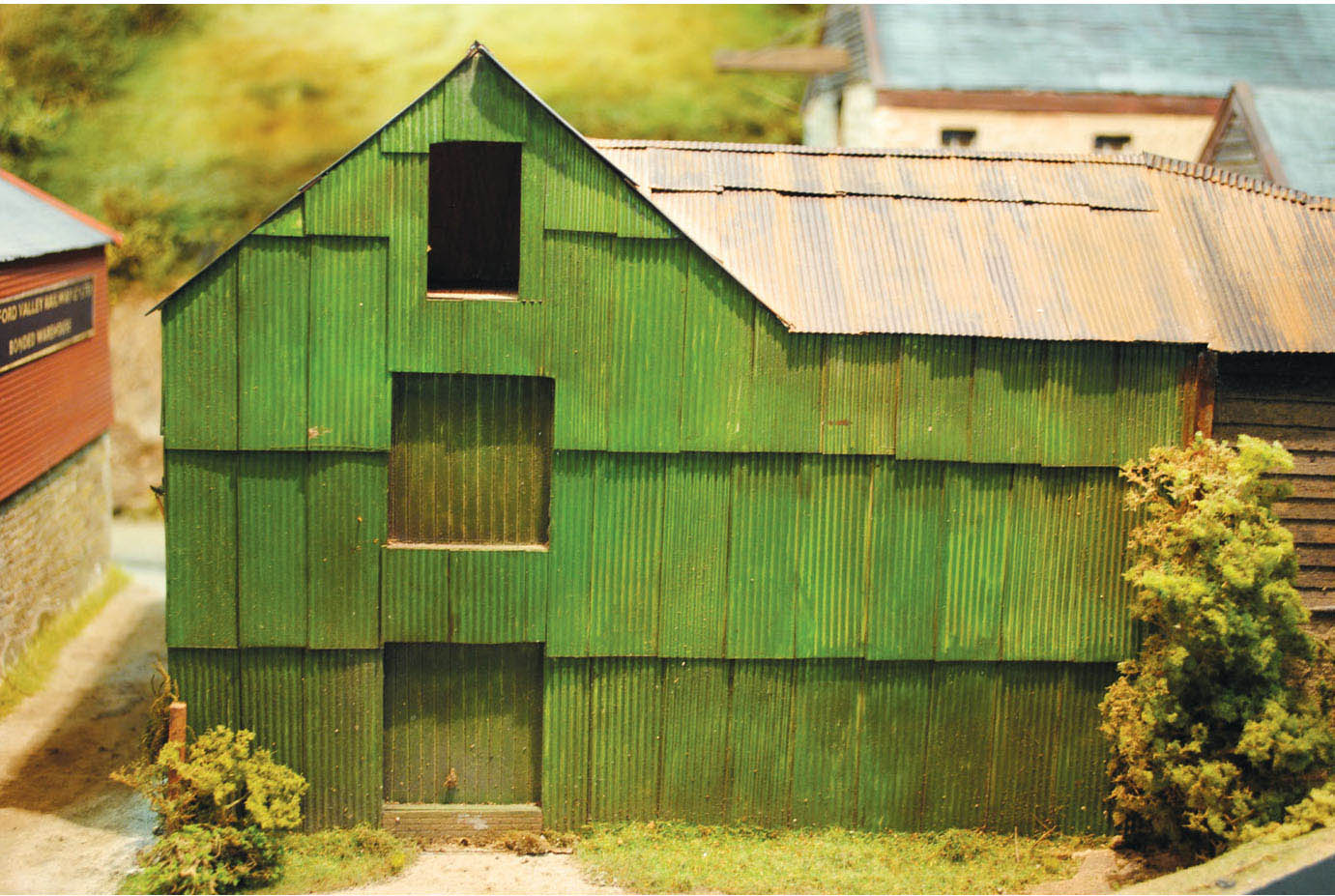
Another building on the same layout was this corrugated-clad warehouse, again the type of building that would fit neatly into the quayside at Portreath.
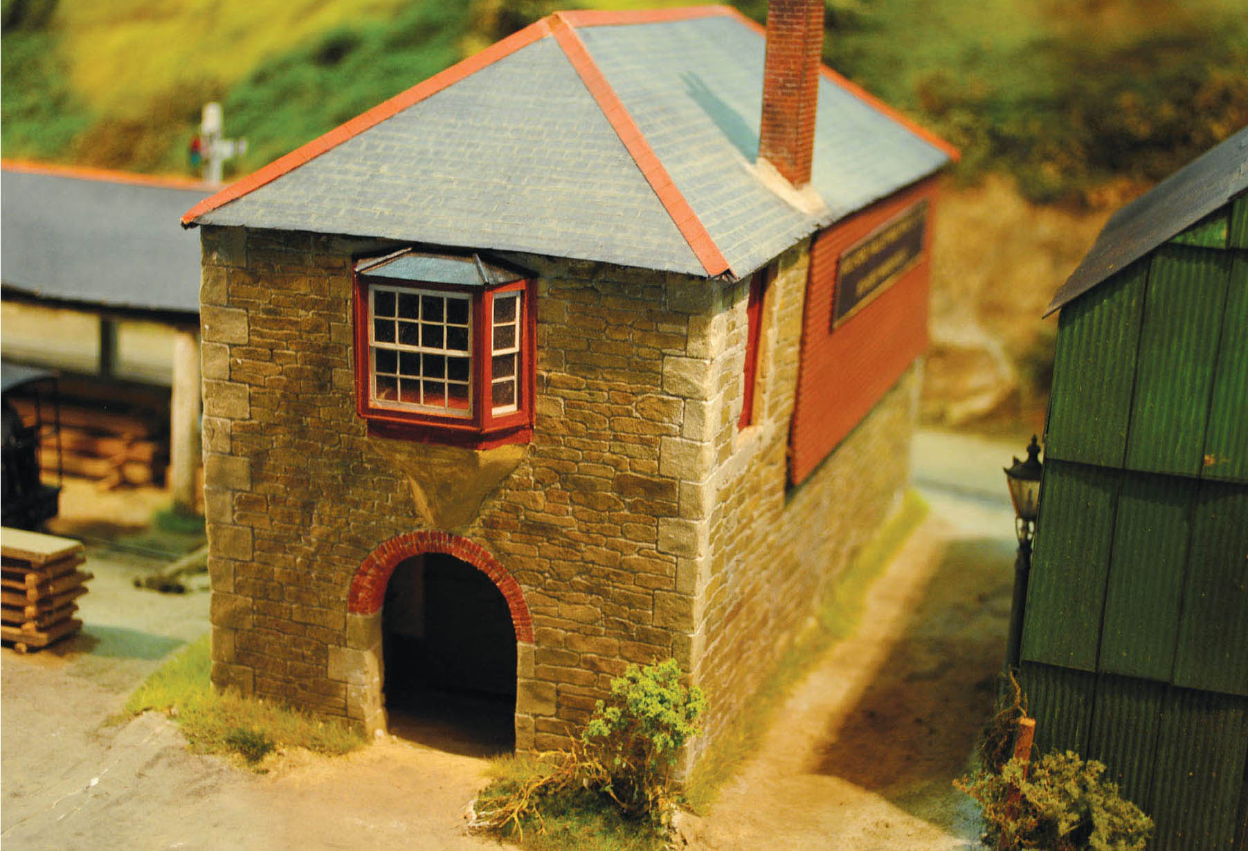
This stone-built harbour office with accommodation for a coach or cart underneath, through the arch, certainly took my attention at the exhibition. The building oozes Cornish character and would also fit nicely into the scene at Portreath. All these model buildings feature on the delightful narrow-gauge layout ‘Gweek North Quay’.
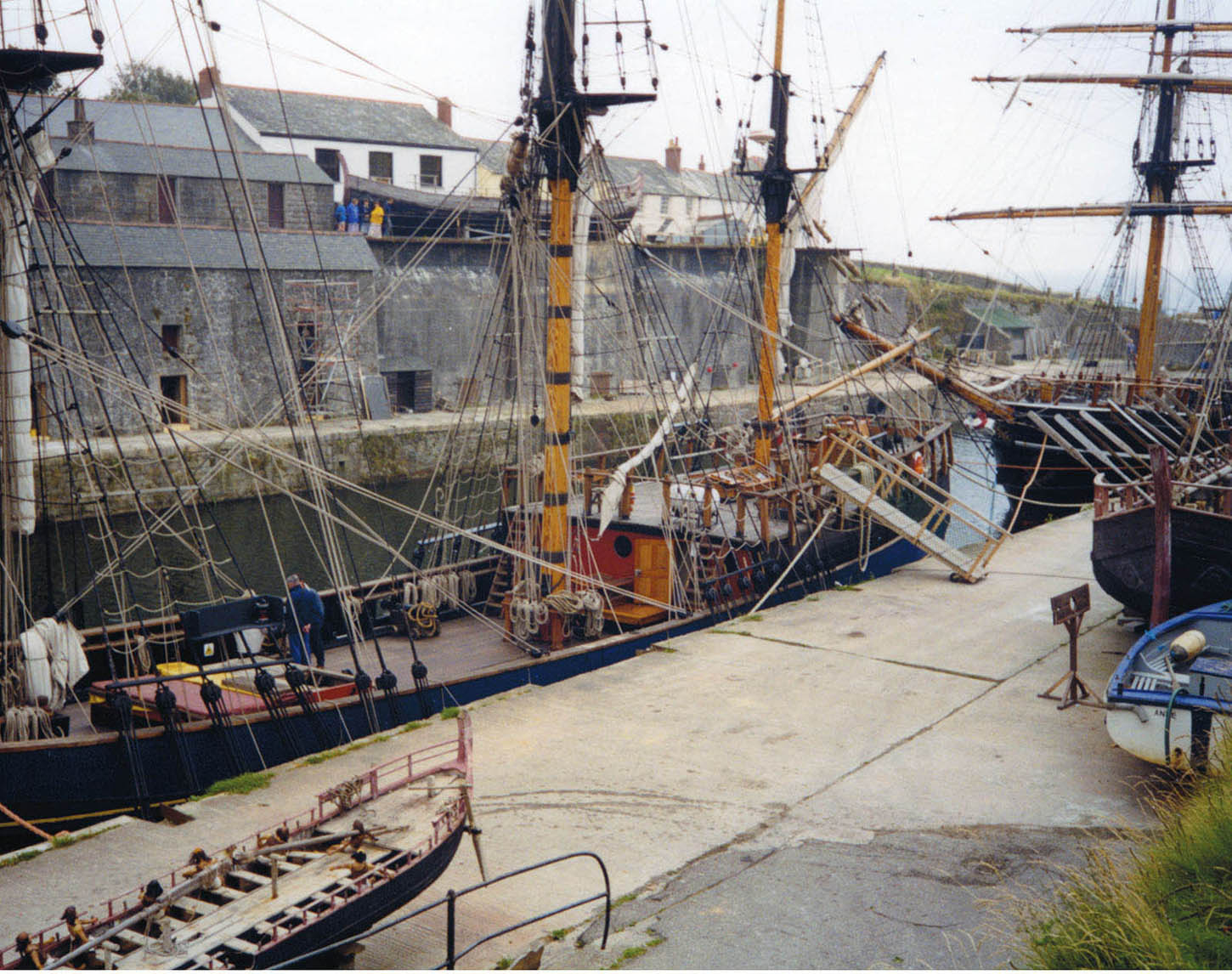
The quayside at Charlstown. The stone retaining walls, buildings and loading chutes at this Cornish port are very similar to those seen at Portreath. The squarerigged ships would also be appropriate to anyone deciding to model this period.
In 1887 a tin streaming plant was built, to reclaim the tin from the Red River, a stream that ran out into the harbour. The tin had escaped from the mine workings in the water that drained away, and found its way into the stream. The plant featured a steam engine, and even when the main structure was eventually demolished, the tall chimney remained intact for many years.
The end of the branch came with the removal of the stationary engine in 1938, then in 1940 the rails were lifted from the quay and from the incline. The remainder of the track on the branch was lifted and removed in 1945. While most of the buildings were demolished, the stone-built engine house was converted into a private dwelling. The incline has also been reused, forming part of the road access down into Portreath.
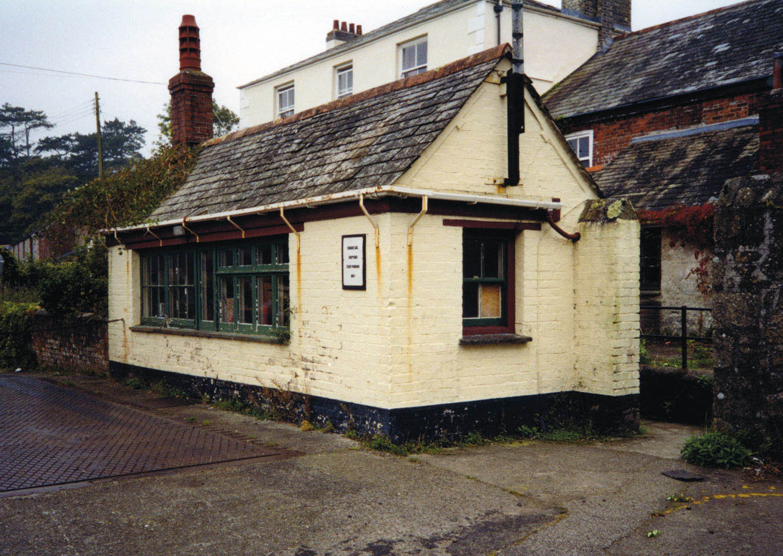
The quay weighbridge and office at Charlstown. This would also be suitable to fit into the model of Portreath.
Portreath harbour would make an interesting model; however, I would concentrate on the north side of the dock rather than the south side. Compromises would also have to be made to the length, and the incline would have to be omitted or reinstated as a level fiddle traverser. Modellers’ licence would permit locomotives to be employed in the harbour section of the branch. The prototype did not have this facility due to the incline, and horses had to carry out all the shunting movements. Later in the book I have included a small layout featuring an incline. This, however, will be used as the fiddle yard, and will be flat. The locomotives were used on the wharf at the bottom of the incline. They were kept in their own small engine shed, so this might be a building worth adding to the Portreath harbour area if choosing this to model.
LONDON’S DOCK RAIL WAY SYSTEM
The largest dockland railway system would have to be that connected with our capital city. The docks spread along the Thames from Tower Bridge as far as Tilbury, but the main concentration was to be found in the area of the Isle of Dogs. The Port of London Authorities principal docks were at their peak in 1955 and consisted, from west to east, the Surrey Commercial Docks, the West India and Millwall Docks on the Isle of Dogs, and the royal docks of Victoria, Albert and King George V. Just about all the larger pre-grouping companies had lines and warehouses linked with docks in East London.
MODELLING LONDON’S DOCKLAND RAILWAYS
Because the docks are so extensive, my suggestion to anyone wishing to create a model would be to choose a small section – then you can concentrate your efforts on achieving a good replication of that section. I have picked one side of the Poplar New Dock as a sample on which to base a small layout; this gives the opportunity to fit in a good amount of track and operating possibilities, together with some large trans-shipment warehouses. The dock will be large enough to place a freighter cargo vessel or quite a few of the smaller lighters. This side of the docks at Poplar was operated by the London & North Western Railway Company, and later the London Midland & Scottish Railway (LMS).

This plan is based on a section of the Poplar Docks Extension in London; this part of the docks was the goods trans-shipment depot for the London & North Western Railway. A) main trans-shipment warehouses B) goods trans-shipment sheds C) dock offices D) goods offices.
PORT PENRHYN AND PORT DINORWICK
I have chosen Port Penrhyn and Port Dinorwick as possible prototypes. Both would make interesting models because of their unique mix of standard gauge with narrow gauge.
PORT PENRHYN
The port was established as a transhipment point as far back as the eighteenth century. In the early days it was connected to the slate quarries at Bethesda by a primitive tram road. Around the turn of the century, the crude track was re-laid with proper edged rail, becoming one of the earliest tramways to use this type of rail. This was the only rail connection with Port Penrhyn until 1852 when a branch was opened from the main Chester to Holyhead line by the London & North Western Railway. The short line was built to the wharf to cash in on the slate traffic. It was not until twenty-five years later that the railway built a branch direct to the source of the slate at Bethesda quarries.
PORT DINORWICK
Just along the coast of Caernarvonshire from Port Penrhyn was the second slate port of Port Dinorwick. The ports in the early days were a trans-shipment point where the slate was first loaded on to lighters, before being loaded on to ships anchored in the Menai Strait. There could be up to eight ships being loaded at any time. At the time of the building of the Dinorwick railway only the smaller craft could navigate the upper reaches of the creek, therefore the quays were extended westwards towards the Strait.
At the same time the railway was extended to serve the new quays and dock, although at first this was no more than a jetty. The port was subsequently divided into two sections, with the old inland creek separated from the newer south side extension by a swing bridge. Over the years the port changed dramatically with the establishment of the New Dock Basin, which could handle much greater shipments of slate. However, the basin could only berth the smaller vessels that could come alongside. The swing bridge was later replaced with a more substantial lift bridge.
The railway’s gauge was 24.5in across the centres of the rails, to carry double-flanged wagon wheels that ran loose on their axles. The early rails were made of iron, and the track was chaired to take the weight of the loaded wagons and locomotives, with a wider chair used over the joints. The sleepers utilized slabs of slate measuring roughly 3ft (1m) in length. Extra iron tie-bars were included and bolted down on to the sleepers to keep them within gauge. The narrow-gauge systems entered by descending the port incline from a south-easterly direction, before traversing through a short tunnel. After this the tracks split into short lengths of holding sidings. A weighbridge was provided to weigh the loads of the full wagons at this point.
Before entering on to the quayside the narrowgauge tracks crossed over the port’s standard-gauge connection on a portable rail crossing, and here the rails were temporarily laid over those of the standard gauge. Once on the quayside, the narrow gauge continued in both directions to serve both the older Creek Dock and the newer Dock Basin; it included siding arms running off the main route, almost at right angles. These gave the facility to offload the slate, creating a stacking system on the quayside, before it was then loaded on to the waiting ships. The narrow-gauge system also incorporated a few holding sidings as well as loops.
On the quaysides of the New Basin a connecting line was positioned to run parallel with the quayside. This in turn was connected to the transhipment siding arms by including a wagon turntable for each of them.
The standard-gauge connection was provided by the London & North Western Railway, which constructed the 1852 port siding. The siding ran off the Bangor to Caernarvon branch, then behind the ship repair shops, where it split into two roads. From here it continued through a gate to the inner land side of the quayside. At this point the railway entered the exchange sidings, before terminating alongside the harbour maintenance workshops.
BUILDING MODELS OF PORT PENRHYN AND PORT DINORWICK
For anyone wanting to build a model of either Port Penrhyn or Port Dinorwick, the major attraction would be the opportunity to mix standard gauge with narrow gauge. However, this comes with a few practical challenges and possibly the restriction to scale choice. This is not intended to put you off, but you should consider the options available before you start on such a project. Indeed, if modelled well, they could both make an impressive-looking and operational layout.
The track would need considerable attention, with scratch building being the only option, especially for some of the narrow-gauge point work, where stud points and turntables are used. Some of the parts may be available from specialist narrowgauge model suppliers: it is a case of searching or joining one of the societies or groups.
EDM Models should be able to supply kits of the locomotives employed on both the narrow-gauge systems. For the wagons and other rolling stock, try Port Wynnstay Models or EDM Models again, although these specialize in 7mm scale.

The rebuilt smithy standing in the grounds of St Fagan’s National History Museum, near Cardiff. This slate-constructed building would be suited to include on a model depicting Port Penrhyn or Port Dinorwick.
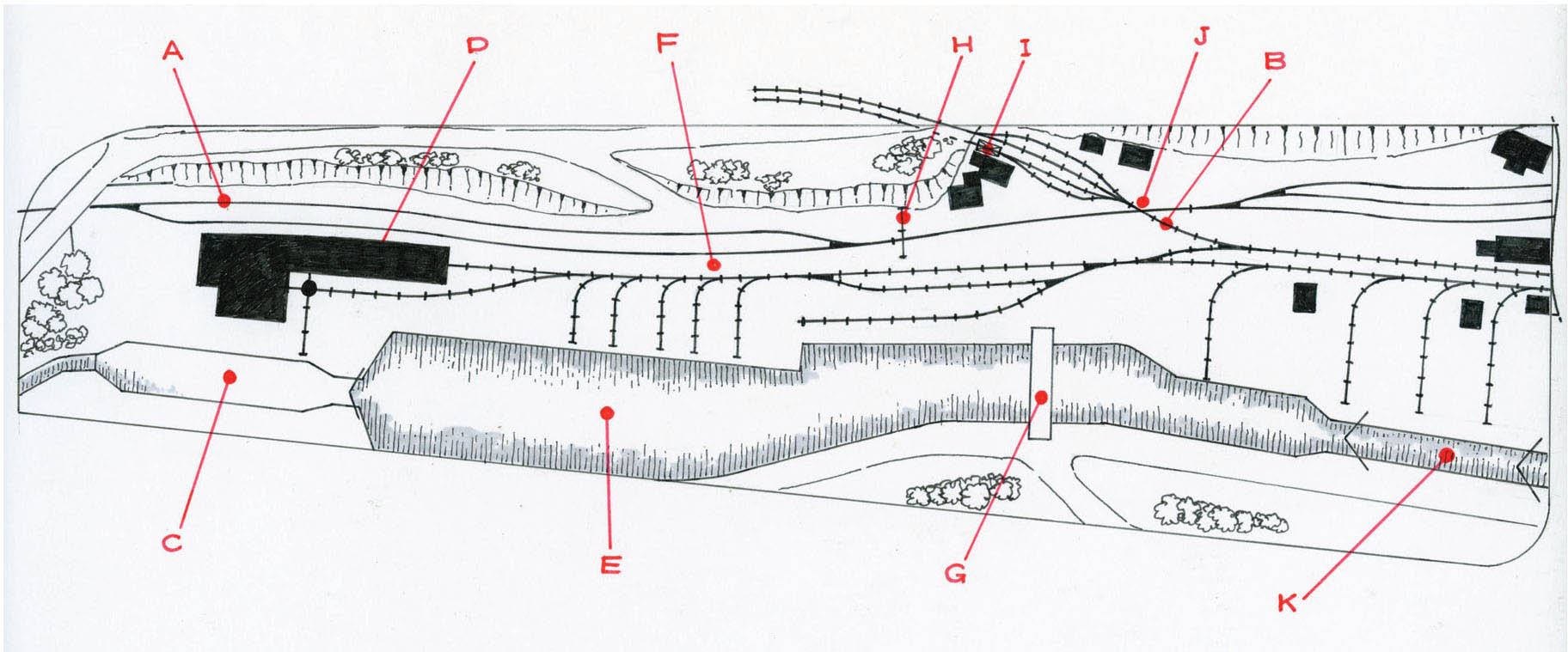
The track plan illustrated is based on Port Dinorwick. For this model I have concentrated on the inland part of the port, extending from the graving dock and ship repair shops to the sea lock. I have also deleted a few of the narrow-gauge slate transfer sidings to condense the length slightly, making it more practical if space is an issue. If, however, you can accommodate more of the model into the space available, then it might be a better option to extend this plan to include the New Basin with its associated slate transfer siding and buildings. The fiddle yards for both the standard gauge and the narrow gauge can be located on the left-hand side, with the overbridge and the tunnel making the perfect scenic breaks. A) London & North Western Port Siding (standard gauge) B) the Dinorwick quarry lines (narrow gauge) C) the graving dock D) ship repair shops E) main dock F) loading platform G) lifting bridge H) gates I) weighbridge J) level rail portable crossing (narrow gauge over standard gauge) K) sea lock.
The harbour town of Fleetwood was the creation of local landowner and MP Sir Peter Hesketh Fleetwood. It was Sir Peter’s vision that the town and harbour would be complementary to the rapid growth of the port facilities of Liverpool, and the location on the north-west corner of the Fylde was ideal for the construction of the port. Work started under the Wyre Railway Dock & Harbour Act for both the town and port in 1835, and by 1840 all the key elements of the town had been planned and constructed. At the same time a rail link was commissioned to cross the Fylde to reach the new town. Under a separate legislation the construction of a dock had been authorized. The dock and railway company amalgamated in 1839.
In the following years sufficient facilities had been constructed for the commencement of steamer services to the Isle of Man and other destinations along the north-west coast. By 1849 the Preston & Wyre line had been taken over by the Lancashire & Yorkshire Railway Company and the London & North Western Railway Company. As a result of lack of capital for future development, the docks were taken over by the Lancashire & Yorkshire Railway under the Fleetwood Docks Act of 1871.
The first dock to be created was the Wyre Dock, measuring 1,000ft (305m) long and 400ft (122m) wide, giving 2,700ft (823m) of quayside space. An additional 15-acre (6ha) timber pond was constructed, where timber was floated after being discharged from ships. Adjacent to the Wyre Dock was a large grain elevator and storage silo. The entire dock complex at its height covered around 67 acres (27ha), with over 8 miles (13km) of railway serving the dock. The dock offered a very variable trade including grain, timber and china clay from Cornwall, macadam, esparto grass and finally fish. The increase in traffic, especially with the need to expand the port’s trawler fleet, meant that a new dock was required.
In 1908 the new fish dock was completed by expanding the original timber pond. However, the partial conversion into a fish dock solved only part of the problem, and the rapidly expanding fish fleet required the total conversion of the timber pond into a large fish dock. This was completed by 1911 and included a vast additional railway system to accommodate this increasing trade. New structures and buildings included fish ‘slades’ on three sides of the dock, totalling a length of 2,000ft (610m).
On the opposite eastern side was the coaling wharf, constructed to a design by the Lancashire & Yorkshire Railway’s chief mechanical engineer George Hughes. This wharf, measuring 680ft (207m) in length, featured three large cantilevered cranes supplied by Cowan Sheldons of Carlisle. The travelling cranes traversed along rails with a gauge of 35ft 6in. The cranes were capable of coaling two berthed steam trawlers lying abreast at a rate of 50 tons per hour. These structures, along with the grain elevator on the Wyre Dock, towered above the rooflines. By 1914 the trawler fleet was over 100 vessels, and by 1920 totalled 172.
MAKING A MODEL
Fleetwood Docks would certainly make an interesting subject to model, although anybody attempting this will need to make a choice. The extensive size of the docks would only allow you to model one side of either the Wyre or the New Dock unless room and space was no object. You might decide to build a model in 1:148th scale, in which case a larger portion of the dock, or even the whole dock might be possible. However, for a more interesting model I would suggest you concentrate on replicating the side that gives you the best operating and visual results.
The choice is not limited to the docks, either, since a good model could be made of the china clay wharf or even the steamer terminal. The latter would give you the opportunity to include passenger trains rather than just goods trains. This model would also include the quayside terminus station buildings at Queen’s Terrace, along with the goods warehouse, and if extended, the possibility of including a small section of the tramway system.
Model of an Aspinall 0-6-0 goods engine. These locomotives would have been common working in and out of the fish docks at Fleetwood in pregrouping days and the early LMS period. The model was built by good friend Martin Nield from a Craftsman kit.
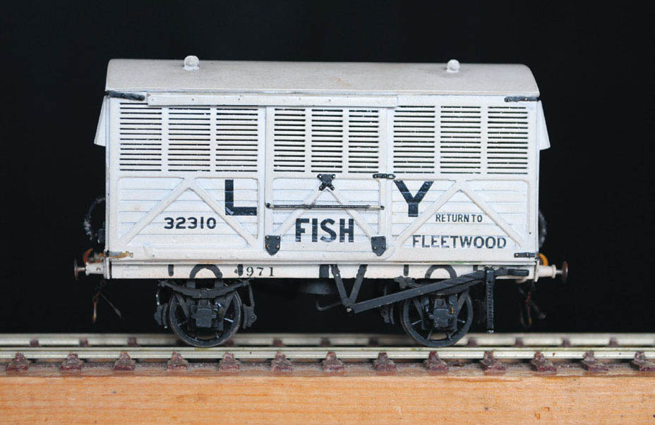
A Lancashire & Yorkshire Railway fish van. Hundreds of examples of this type of van were built to transport fish, and anyone wishing to model Fleetwood Docks at this period would need to include a fair few of these vehicles. The kit was also built by Martin Nield and supplied by ‘Jidenco’, although not now available, while a kit of this type of van is available in the range of wagons produced by David Geen.
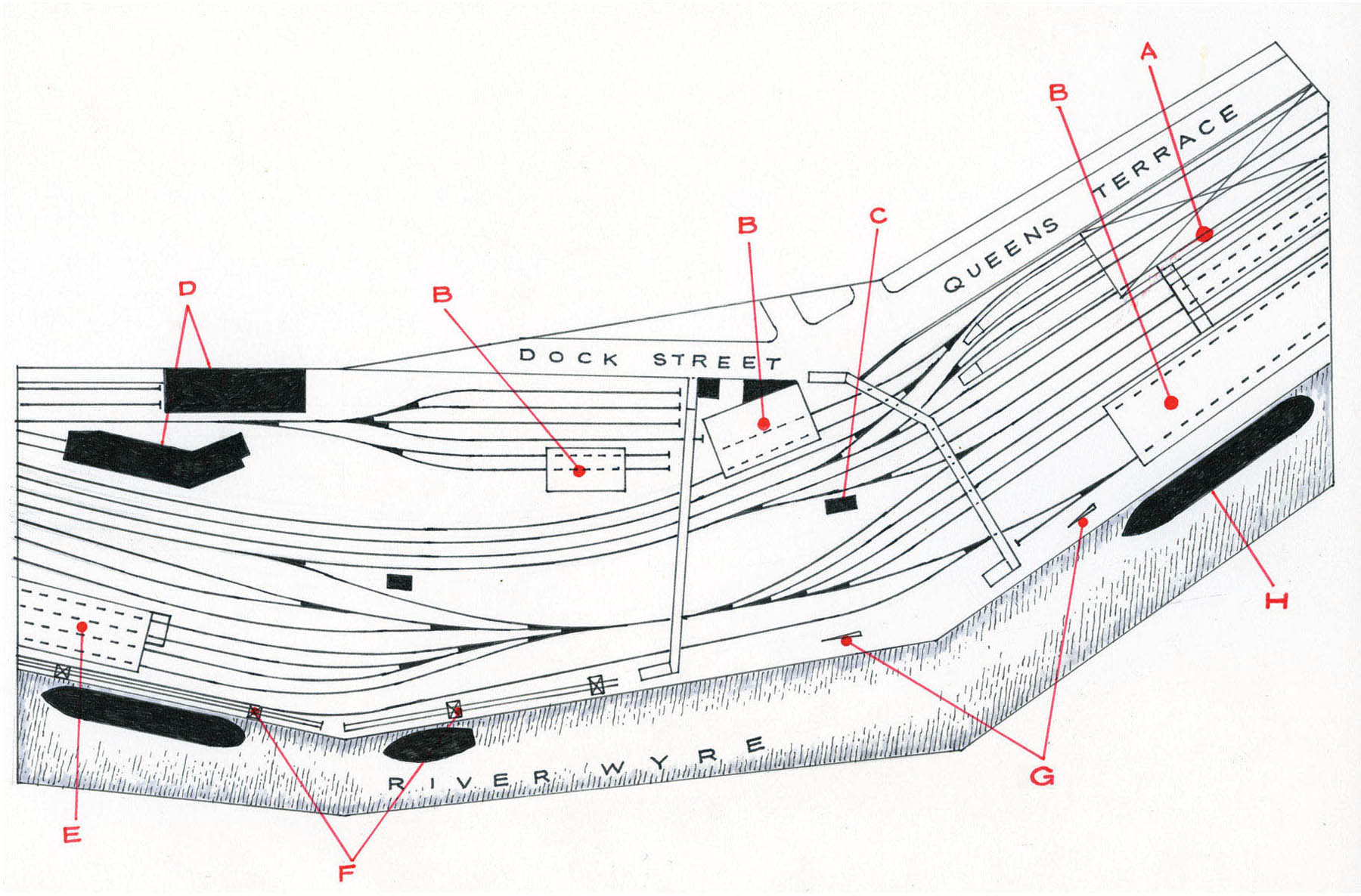
The plan of Fleetwood I have decided to present is based on the station and Ireland ferry quays. It also includes most of the goods sidings and depots, and the china clay warehouse. A) station and train shed B) goods and trans-shipment sheds C) signal box D) warehouses E) china clay warehouse F) travelling cranes G) fixed cranes H) Belfast ferry.
THE NEW PORT OF IMMINGHAM AND THE TRAMWAY SYSTEM (THE CLICKERTY)
For many years Immingham was just a sparsely populated village, standing on the edge of the marshland a mile inland from the south bank of the River Humber. This remote agricultural settlement was situated around 7 miles (11km) from the fishing town of Grimsby.
The village was to change dramatically early in the twentieth century. After the completion of the last main line to be built to the capital, the Great Central Railway was looking to build a new dock. The established docks at nearby Grimsby were very congested by this time, and the site at Immingham was ideal for the construction of a deep-water dock.
Over the next few years the village experienced the massive influx of several thousand men and their families who descended on the area and Immingham was soon transformed, with the excavation of a 45-acre (18ha) dock and a further 1,000 acres (405ha) of land developed. This included the building of many trans-shipment sheds and the laying of acres of railway track.
Three railways were laid to connect with Grimsby, Ulceby and Goxhill, and seven hydraulic coalloading hoists were erected: these were capable of loading around 5,000 tons of coal per hour into the holds of the waiting ships. Along with the hoists, a vast number of holding sidings were laid where the incoming loaded coal wagons could be stored, awaiting their turn for the load to be discharged on the hoists. These sidings consisted of a total length of 170 miles (274km) of track.

This archive photograph taken in 1959 shows the Immingham dock terminus of the Grimsby & Immingham Tramway, with the G & I car No. 3 and the ex-Gateshead car No. 30 at the terminus. Also worthy of note is the freighter The Welsh Prince seen in the background. THE TRAMWAY MUSEUM SOCIETY
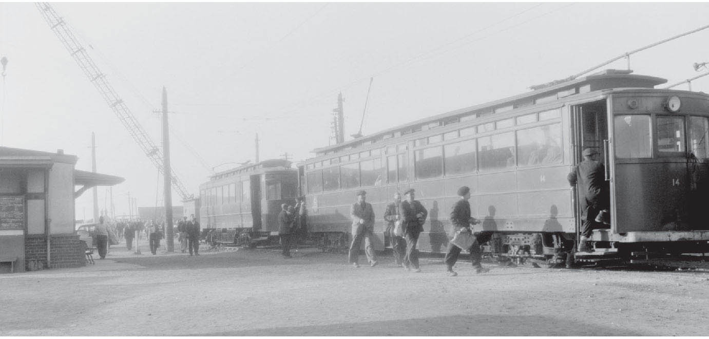
In this archive photograph of 1960, the dockers can be seen boarding car No. 14 at the terminus after a busy shift working in the docks. THE TRAMWAY MUSEUM SOCIETY
Besides the coal operations, a massive grain storage plant was built, and a number of cranes were installed on this side of the dock to load and discharge a host of general cargoes, with timber from the Baltic being the most common.
To enter the deep dock a lock was provided, with two sets of massive steel gates to allow the larger ships from the Humber passage into the dock. Alongside the lock the dry or graving dock was constructed. Two wooden jetties projected out from each side of the lock entrance.
With the construction of the extensive docks at Immingham, it soon became apparent that a transport system was required for the benefit of the dock workforce. To this end, the Great Central Railway built a unique tramway system linking the neighbouring town of Grimsby to the dock at Immingham. The resulting electric-powered system was laid along the streets to reach its dock-side terminus.
The tram cars were built especially for the system by Brush of Loughborough, with the first service running in 1912. The power for the system was provided by the newly built power station at the dock, using an overhead wire system for the electrical contact. Other cars were purchased as replacements to the fleet from Newcastle & Gateshead Corporations, when their system had closed. The depot was located at Pyewipe, where all the cars were stored and maintained. They were originally supplied in the Great Central livery of lined-out dark green. The company’s coat of arms, with its swash containing the word ‘Forward’, was positioned centred on the front and rear panels.
The cars sported a simplified livery of green when under the grouping ownership of the London & North Eastern Railway. But after nationalization in 1947 the trams became part of British Railways, who spruced up even the drab dark green livery of the tram-car fleet, giving them a brighter green coat, known as British Railways ‘electric green’, with the BR emblem now appearing on the side panels.
The two wooden jetties also had a railway connection, with the eastern jetty having a passenger terminal. This was used extensively during the summer months of the 1920s and 1930s, as Immingham was the starting point for the ‘Midnight Sun’ cruises, when the passengers had the convenience of walking just a few yards from the train to the gangplanks of the waiting ships. The Orient Line organized these popular cruises to the coast and fjords of Norway. The western jetty has a separate straight rail jetty connecting the shore to the main structure. This was provided with a wagon coal hoist to supply the steam ships visiting Immingham with fuel for the boilers.
MAKING A MODEL
Making a model based on Immingham would again be restricted to concentrating your modelling efforts to just one area. This might be the eastern jetty with the railways terminal to serve the Norwegian cruise liners docking here; or it might be the other jetty featuring the railway coal hoist system to load the bunkers of the steam ships. Alternatively you might choose to model the quaysides of the inner deep dock, again with the array of coal hoists positioned on one side for loading the collier ships; or the unique Grimsby & Immingham tramway system, featuring the dock terminal. If, however, you have sufficient room, you might be able to combine the tramway terminal with the railway serving the liner terminal on the eastern jetty. Whatever your choice, careful planning will be required if you want to resemble anything like the prototype.
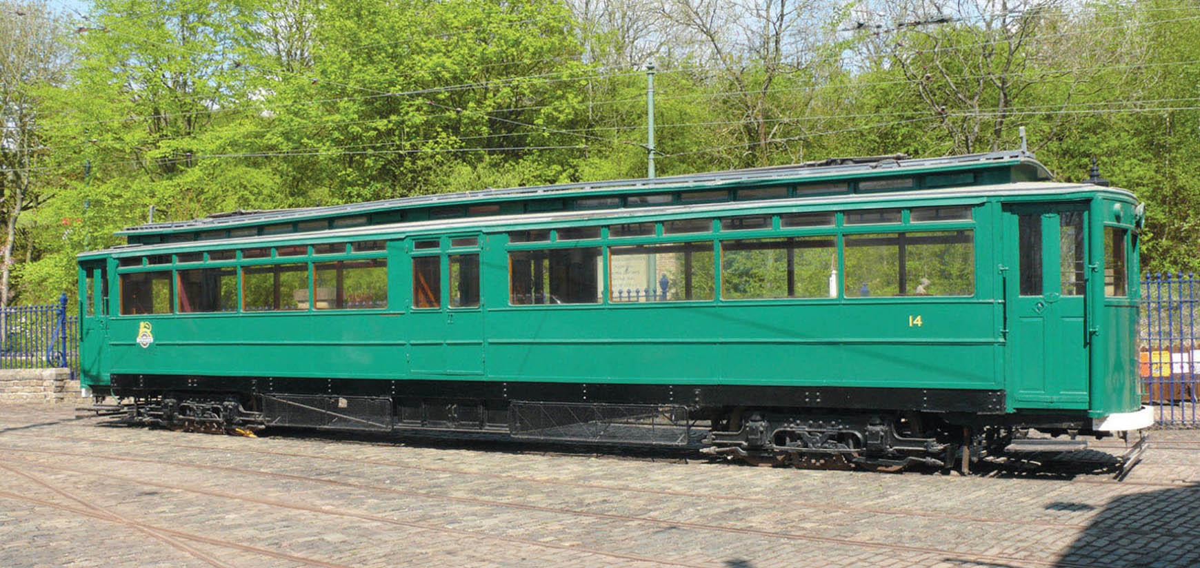
Pictured at Crich Tramway village is the preserved Grimsby & Immingham tram car No. 14 carrying the lighter (electric) green livery and early crest of British Railways. MALCOLM WRIGHT
For this plan I have decided to concentrate on just the eastern jetty at Immingham. This has been purposely chosen to include the dock terminus of the Grimsby & Immingham Tramway. A) traverser B) Grimsby & Immingham Light Railway C) Great Central Railway eastern jetty branch D) ‘Orient Line’ cruise ship E) eastern jetty light F) tram terminal G) customs house.

A model 1:76th scale of the Grimsby & Immingham tram car No. 14. The car has been built from a ‘Grime Street Industries’ kit by Alan Kirkman. ALAN KIRKMAN
The busiest and most interesting years to model would probably be the inter-war years. This would give plenty of scope for modelling both the trains and the tramway system, together with an interesting variety of visiting ships. Let us not forget the actual war years, either, as Immingham played a vital part during both World Wars, becoming a base port for the Royal Navy’s flotilla of submarines and torpedo boats. This period might appeal to some modellers, as it gives the opportunity to model and run trains helping with the war effort.
SHOBNALL BASIN
For this prototype I have selected another canal wharf. In the years 1769 and 1780 a link was constructed for the Burton Boat Company between the Trent & Mersey Navigation and the River Trent. This short canal of just over 1 mile in length started near to Shobnall, and finished at Soho Wharf on the river in an area of Burton known as Bond End. The new cut took this name and became known as the Bond End Canal.
The original aim was for the trans-shipment of goods at Shobnall on to barges, which would then pass along the River Trent as far as Gainsborough. The canal, however, had mixed fortunes with the amount of traffic it carried, but the North Staffordshire Railway Company showed an interest in it, and in 1847 it was absorbed by the railway.
The building of the extensive brewery railway system, along with the decline in traffic, soon led to the closure of the canal, and not long after the cut was filled in. The Midland Railway built a connecting branch line to the breweries at this side of the town along the old canal bed, the railway becoming known as the Bond End Branch.
The canal remained a short distance, terminating at the end of the basin at Shobnall. The Midland and the London & North Western Railway company constructed extensive exchange sidings here to handle the beer traffic. A rail extension from the sidings linked them with the wharf, with tracks running alongside the basin. The wharf’s main cargo was coal, although other goods such as timber for use in the cooperages may have been transhipped or offloaded here. The coal wharf remained until the railway sidings closed in the late 1960s.
By this time the basin was in a state of dereliction, with local businesses using it as a tip, and all the buildings demolished. One building that met this fate in the early 1960s was the public house ‘The Mount Pleasant Inn’. The pub stood alongside the junction of the Trent & Mersey and the Bond End canals, and became known with affection as ‘Bessie Bulls’, a name that came from the original landlady of the pub, and it continued to be called this right up until its demise.
MAKING A MODEL
For any person wishing to ‘have a go’ at modelling Shobnall there is again a choice. I have presented the more condensed version concentrating on the wharf, but this could be extended to include the entire exchange sidings if you have the space. The far western end is the subject matter for our model, with the extended coal sidings fronting the layout. The rear of the layout includes the single-track branch leading to Marston Thompson & Eversheds brewery, and this railway runs the full length of the model, running off the visual section at both ends. It starts on the level at the exchange sidings end, then gradually climbs to cross the canal at the other.
The main buildings to feature on the layout will be the canal pub ‘Bessie Bulls’ along with the stables. In real life the entrance to the wharf still has one of the original James Brindley bridges, and this structure would make an interesting feature to add to the model. The brewery branch will also need a bridge constructing. In reality this bridge consisted of steel-plate girders supported on brick abutments, and in fact one side of it still remains today as it carries the main waterpipe over the canal for the brewery.
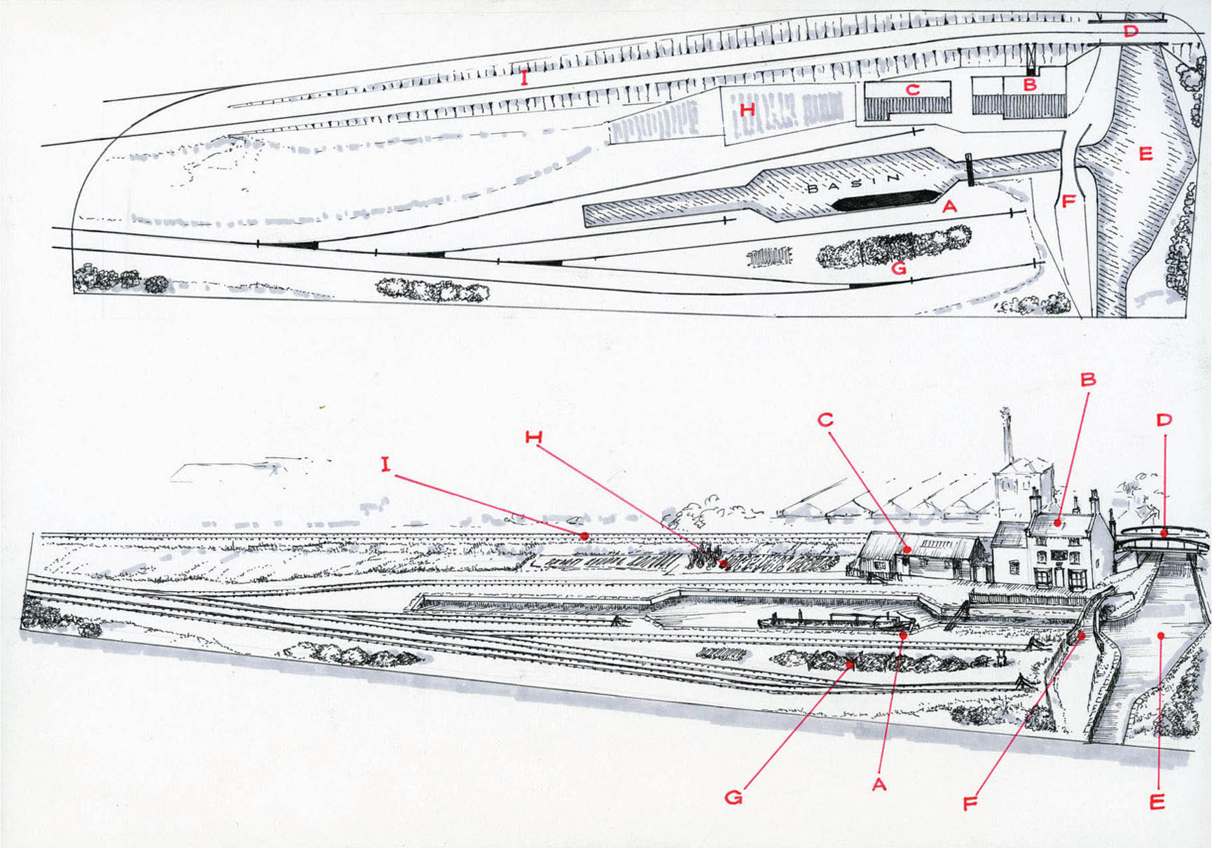
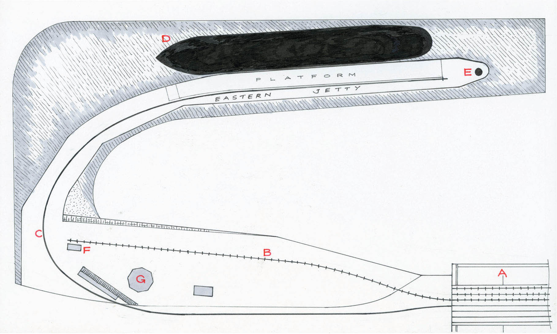
I have combined the track plan of Shobnall with a three-dimensional illustration to show what the model would look like. A) coal basin B) The ‘Mount Pleasant Inn’ public house (Bessie Bulls) C) stable block D) plate girder bridge E) winding hole F) bridge number one G) coal bunkers H) allotment gardens I) Marston’s Brewery branch incline.

I created this oil painting of Shobnall wharf to be used as a Christmas card some years ago. I have included it because it shows the basin, along with a couple of British Waterways boats moored up against the coal wharf. The composition also shows the pub and the towpath bridge, together with a locomotive bringing beer from Marston’s Brewery in the background. All this would be valuable reference for anyone wishing to construct a model.
This model layout would work in both 1:76th scale and 1:43rd scale, depending on how much room you have. The coal wharf would have seen many different classes of locomotive working from the exchange sidings. The Midland types were the most common in the later days of the wharf’s existence, with a few diesels also making an appearance. Most of these are available as ready-to-run models. Midland classes of 4Fs, 3Fs and 3F Tanks known as ‘Jinties’ – or ‘Jockos’ as the Burton loco men called them – are produced by Bachmann. These classes are also produced in kit form if you choose to model in 7mm 1:43rd scale.
The brewery branch, however, would only have seen the locomotives belonging to the brewery. Hawthorn Lesley Saddle Tanks were the types used, with No. 1 and No. 2 employed in the early days, and No. 3 and No. 4 taking over in the later period. All these locomotives were given a large nameplate which read ‘Marston Thompson & Evershed’. Locomotive No. 4 was converted to a diesel in the later years, and is now preserved and can be found in the collection at the Chasewater Railway in Staffordshire. No. 3 is also in existence, although it was still in bits at the Foxfield Railway the last time I saw it. The Hawthorn Lesley industrial Saddle Tanks should be available in kit form in both scales.
You will require a number of open wagons as well as several goods vans. The brewery would have preferred box vans for the transportation of beer. Some vans were built especially for the breweries with louvred sides creating extra ventilation to keep the beer cool. If you choose the larger scale for your model, there is a kit of this wagon produced by ‘Parkside Dundas’. Before these wagons became available, the breweries used redundant Midland Railway cattle vans for this purpose.
The pub had its beer delivered direct from the trains passing the rear of the building as they left the brewery. Two wooden rails were positioned on the embankment, so the barrels could be rolled from the wagons straight into the pub’s cellar. This would make an interesting cameo scene to add to the model.
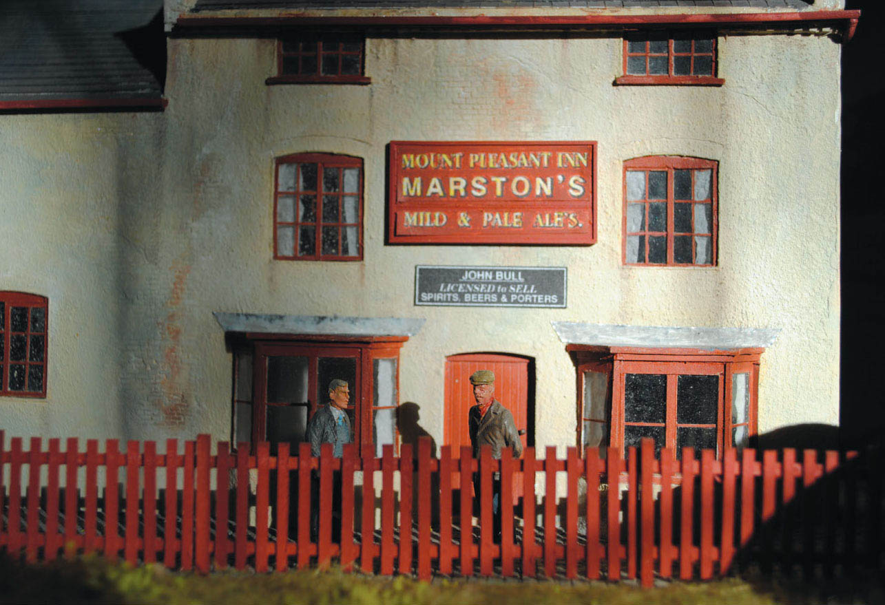
Besides the painting, I also made a 7mm model of the pub for display at the IWA National Festival at Shobnall Fields back in 2011. Although the canal pub was called ‘The Mount Pleasant’ it was always known locally as ‘Bessie Bulls’, after the infamous landlady who first kept the hostelry. For anyone attempting this model the pub would have to be the main feature.
SOUTHAMPTON, ISLE OF WIGHT FERRY TERMINAL
The early ferry terminal for the Isle of Wight ferry was situated in the harbour at Southampton. The terminal built at the end of the pier or jetty had a direct rail link with the station platform positioned at the end. Passengers could walk the last few yards down the inclined gangway to the floating pontoon where the paddle steamers were moored. The buildings at the end of the pier featured a cafeteria where passengers could refresh themselves before embarking on the short voyage over to the island.
MAKING A MODEL
Most railway terminals on a jetty or pier such as this only require a single track, or a single track with a run-round loop. This prototype follows the latter, and has a long run-round loop, together with an extended head shunt. It would make an interesting model with the jetty extending into the harbour constructed from chunks of stone, with the last part built from timber and iron.
The scenic modelling would be an interesting challenge, with the deep waters of the harbour replicated at the end of the pier. The stone jetty might also have to be modelled using real stone to make it look convincing.
The choice for the model would have to be the pre-grouping period, with classes of locomotives and coaching stock from the London & South Western Railway. This period of the railway and the inclusion of one or two of the Isle of Wight paddle steamers would be a challenging project, but if you choose to model this interesting ferry terminal, I am sure it will certainly be rewarding.
The prototypes and layout suggestions given here are only a few that I have selected, and there are, of course, many others that the modeller could choose. However, the selection I have presented should give plenty of variation and scope to make some interesting models. By selecting any of these and then by applying some of the techniques and using the materials suggested in this book, hopefully you will be inspired to have a go. Remember this book is only a guide, and the fun of the hobby is discovering the talents you might not realize you have.