10
Interlaminar and Out-of-Plane Shear Stress
10.1. Tension of a cross-ply laminate [0,90]S
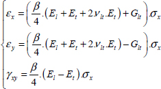
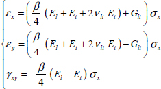
If we perform the tension of two laminates [0°]S and [90°]S independently with an imposed strain εx equal for both laminates, we then obtain shrinking along the y-direction:
For laminate [0°]S:
For laminate [90°]S:
The laminate at 0° will therefore shorten a lot more than the laminate at 90°. For example, for the aforementioned T300/914:
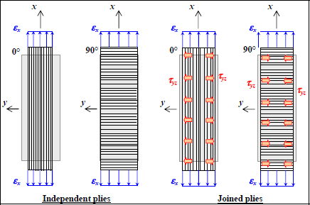
Figure 10.1. Diagram of interlaminar stresses during the tensile test of a laminate [0,90]S. For a color version of this figure, see www.iste.co.uk/bouvet/aeronautical2.zip
If we now perform a tensile test on the laminate [0,90]S with the interface imposing the same strains on all the plies under in-plane loading, shear stress τyz will appear at the level of the interfaces. Since the lateral faces are free, we will necessarily have τyz null on these two faces (of normal vector y). We can also show that this shear stress is practically null at the center and maximum near the edges (while being null at the actual edges):
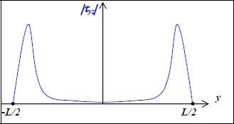
Figure 10.2. Diagram curve of the interlaminar stress during the tensile test of a laminate [0,90]S
We will therefore see that interlaminar stresses appear on a composite structure, especially near the free edges, and therefore the potential appearance of delaminations.
10.2. Tension of a cross-ply laminate [45,–45]S
If we perform the tension of two laminates [45°]S and [–45°]S independently with an imposed strain εx equal for both laminates, we then obtain opposing shear strains on both the plies:
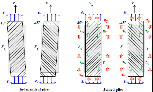
Figure 10.3. Diagram of interlaminar stresses during the tensile test of a laminate [45,–45]S. For a color version of this figure, see www.iste.co.uk/bouvet/aeronautical2.zip
For laminate [45°]S:
For laminate [–45°]S:
If we now perform a tensile test on the laminate [45,–45]S, the interface will impose the same strain on both the layers with a null shear strain. There is then creation of a shear stress field τxy in each ply. Furthermore, the edges being free of any external stress, the stress must be null on all four faces of the plies (faces of normal vectors x and y). This stress τxy is itself transmitted from one ply to another via the intermediary of shear stress τxz throughout the interface. For example, at the center of the specimen (in x = 0), we get:
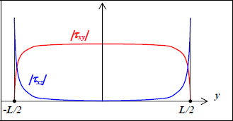
Figure 10.4. Diagram curves of interlaminar stresses during the tensile test of a laminate [45,–45]S. For a color version of this figure, see www.iste.co.uk/bouvet/aeronautical2.zip
These phenomena of interlaminar stress are high on the free edges of the composite structures, and more particularly at the level of the holes where, in addition to the free edge phenomena, there exist phenomena of stress concentration due to the presence of the hole, which will amplify the phenomena.
10.3. Out-of-plane shear stress
So far, we have supposed that the laminate was sufficiently thin to support in-plane stresses. The reality is obviously more complex, for instance, for thick laminates, the out-of-plane shear stresses, and in particular the out-of-plane shear stresses τxz and τyz, are non-negligible. We can also show that they are tied to the variations in the plane, and obviously eventual out-of-plane loads. If we write the equilibrium equation in the absence of volume forces:
We obtain along x- and y-directions:
And, having seen the hypotheses performed on the displacement field, we get:
We can then obtain the shear stress variations of τxz and τyz, and we can then demonstrate that they are parabolic for each ply. Furthermore, they must be null for upper and lower faces of the plate and continuous at the interfaces; they will appear as follows:
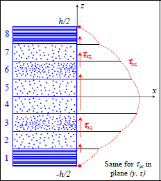
Figure 10.5. Diagram curve of out-of-plane shear stresses of a laminate. For a color version of this figure, see www.iste.co.uk/bouvet/aeronautical2.zip
They are generally maximum at the center of the plate and can cause two fracture mechanisms:
- – The fracture of the plies located at the center of the plate under out-of-plane shear stress. These fractures are characteristic because they are globally oriented at 45°.
- – Interface fractures. Indeed, these stresses will have to cross through the interfaces in order to pass from one ply to the other and will therefore overload there.
In practice, these two phenomena are intricately linked, and in particular the stress concentration present at the end of a matrix crack under out-of-plane shear stress will tend to initiate delamination.

Figure 10.6. Diagram a) [CHO92] and micrograph b) [PET05] of the interaction of matrix cracks (due to out-of-plane shear stress) with delamination


