8
Cable Analysis
After studying this chapter, the student will be able to:
- – distinguish between rigid and deformable cable structures;
- – be familiar with the funicular shape of a cable structure;
- – analyze cable structures subjected to concentrated and distributed forces;
- – calculate the thrust of the support system and the maximum tension.
In the first section, we analyze cable structures subjected to different loads, which includes concentrated forces, uniform forces and other forces. For each load, we evaluate the thrust, tension and deflection of the cables. In the second section, we describe how to analyze a cable when the inflection point is located outside the cable. Finally, we present an overview of the analysis of suspension bridges.
8.1. Introduction
Cables have been used for centuries and are chosen because of their structural performance, light weight and aesthetic appearance. Cable structures can be divided into two categories: (1) rigid cables and (2) deformable or flexible cables. This classification is based on the cable’s deflection and geometry when loaded. Rigid cable structures can bear external loads without any change to their geometry. Conversely, deformable cable structures have an observable deflection when loaded. However, it is necessary to assume that the deflections are small.
The role of cable structures is to bear the loads from their own weight (dead weight) and the live loads of the arches, suspended roofs and bridge structures as they are transmitting loads from one element to another. The dead weight of relatively short cables is neglected, but when cables are used in electric or transmission lines the weight must be considered.
Cables are structural elements used in various constructions including suspension bridges, support wires, transmission lines, electrical networks, stadiums and covered sports halls (Figure 8.1). The cables are intended to withstand traction forces but they have no resistance to bending, shear stress, compression or torsion. Their mode of resistance is traction, generally directed along the tangent of the cable from a given point.

Figure 8.1. Cables1
In addition, cables are key elements of structural behavior; they are currently used in modern structures. They can be temporarily used as ropes to stabilize ships and boats, for example.
8.2. Mechanical characteristics of cables
The cables used in the field of construction are characterized by high mechanical strength and high fire resistance. They are flexible and coiled to increase their mechanical efficiency. Cables can cover large-span structures. Their efficiency increases with increasing length and they can reach hundreds of meters.
The cables are characterized by their shape (curvature), which depends on several parameters, such as the nature of the force, the point of the force’s application, the length of the cable and the placement of the supports.
Cable structures are classified according to their treatment of the dead weight:
- – cables with the dead weight neglected;
- – cables with the dead weight considered.
Depending on the loads applied, the cables take on different geometric shapes.
8.3. Hypothesis of cable analysis
To analyze cable structures, it is necessary to consider the following simplifying assumptions:
- – the cables are inextensible and perfectly flexible;
- – the cables have no resistance to bending or shearing;
- – the internal force in the cables is traction, directed along the tangent to the curve at a given point;
- – the horizontal component of the tension force at the support is called the system thrust.
8.4. Cable analysis
The role of cable structures is similar to that of other types of structures. The primary goal is to transfer actions from one element to another (on the ground). In a guyed bridge, for example, the internal forces are transferred from the slab to the transverse cables and then to the longitudinal cables.
Depending on the loads applied, we can distinguish two categories: (1) cables stressed by concentrated forces and (2) cables subject to distributed loads. In cable structure analysis, the flexibility of the cables makes it possible to neglect the shear and flexural strength while the inextensibility makes the cable length constant before and after the loading system is applied. This allows us to state that the geometry of cable structures retains its initial configuration after external loads are applied.
8.4.1. Cables subject to concentrated force
The cable (Figure 8.2) is stressed by a concentrated force P and each portion is a straight segment.
1) Direct method
Determine the shape of the cable if the system thrust is H.
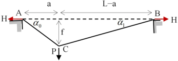
Figure 8.2. Given cable
The support reactions are calculated using equilibrium equations (Figure 8.3).


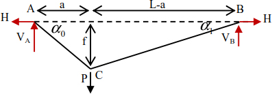
Figure 8.3. Free-body diagram
Given that  , the inclinations of the cable are given as
The tension forces in the portions of the cable can be deduced by


EXAMPLE 8.1.–
For H = 24 kN, P = 20 kN, a = 10 m and L = 25 m, the internal forces and maximum deflection (Figure 8.2) are given as
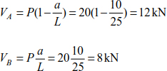
The forces in the portions of the cable are

The inclinations of the segments are
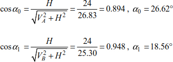
The deflection of the point of application of force P is

2) Inverse method
The inverse method evaluates the system thrust when the total length of the cable is known.
The total length can be deduced by
Substituting equations [8.3] and [8.4] in the relationship [8.7], we obtain
After setting  and
and  , equation [8.8] is written as
Resolving equation [8.9] means we can evaluate the system thrust.

EXAMPLE 8.2.–
Example 8.1 is repeated again.
The total length of the cable is given by the relationship [8.7].
Where Lt = 30m
Therefore, δ = 0.40 and λ = 1.20.
The system thrust is given as

We find a gain on the system thrust of 26.6%.
EXAMPLE 8.3.– Cables subject to multiple concentrated forces
The cable structure (Figure 8.4) is solicited by concentrated forces. The deflections of points B, C and D are, respectively, yB, h and yD. It is necessary to determine the support reactions, the tensions in the cable sections and the height differences yB and yD.

Figure 8.4. Cable structure under concentrated forces
Evaluating the support reactions is carried out using the static equations (Figure 8.5).

Figure 8.5. Support reactions

Hence

It can also be written as

The equation of vertical equilibrium leads to

In the same way, the sum of the moments relating to point C is
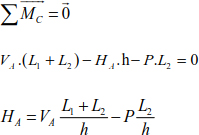
The thrust to support E is

The deflections of joints B and D are


To determine the tensions in cables (AB), (BC), (CD) and (DE), we use the equilibrium equations for each cable.
Segment (AB)

Segment (BC)
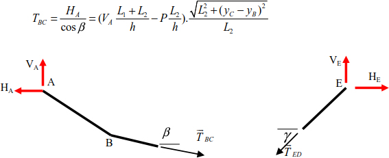
The same method applies to bars ED and DC.
Segment (ED)

Segment (DC)

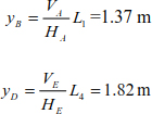
In this particular case: L1 = L4 = 4m, L2 = L3 = 3m and h = 2m .
The formulas above lead to the determination of the reactions

and 
The deflections of points B and D can be deduced by
The tensions in the cable sections are
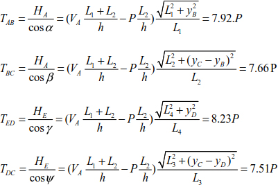
The diagram of the tensions in the cable segments is shown in Figure 8.6.

Figure 8.6. Normal force in cable sections
8.4.2. Cables subject to distributed forces
The cables are used to bear permanent loads and live loads. In the case of a guyed bridge, for example, the longitudinal cables are held by a series of transverse cables, which are generally regularly spaced (Figure 8.7).
In this case, it is necessary to determine the curve of the passage of the longitudinal cables, which depends on the number of transverse cables (that is, the number of concentrated forces). For ease of analysis, the concentrated forces applied to the cables are replaced by a uniformly distributed load (Figure 8.8).
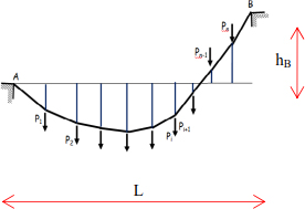
Figure 8.7. Cable under concentrated force
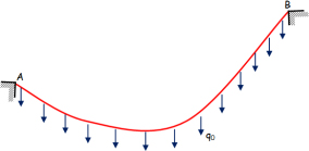
Figure 8.8. Cable under distributed force
Generally, a portion of cable of length Δx is acted upon by a variable load q(x) whose ends are subjected to tensions T (x) and T (x) + ΔT (x) (Figure 8.9).
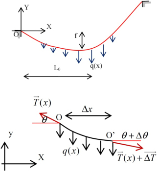
Figure 8.9. Cable portion
The static equations allow us to construct the following equation system:
Equations [8.11], [8.12] and [8.13] can be simplified when Δx → 0, Δy → 0, Δθ → 0 and ΔT → 0.
The successive integration of equations [8.14] to [8.16] leads to


where q(x) is assumed to be constant along Δx. The constants C1 and C2 can be deduced by applying the limit conditions.

Using equation [8.16], and given that  and
and  , we can write
If we suppose that q(x) = q0, the curve equations of the cable become

Knowing that  .
.
Finally, the parabola equation is

Knowing that y(0) = 0, the system thrust is

Using equations [8.19] and [9.20] allows us to determine the tension in the cable.
The maximum tension in the cable can be determined using the relationship [8.23].

- 1) Direct method
The cable is acted by a uniformly distributed load with an intensity of q0 (Figure 8.8). It is customary to write
where Δs is the curvilinear length of the cable.
Substituting relationship [8.26] into [8.25], we obtain
The length of the studied element is very small, thus equation [8.27] is written in the following form
Substitute the relationship [8.28] with the relationship [8.21], we obtain

By the resolution of equation [8.21], the cable slope expression is given as
We derive equation [8.30] and use equation [8.15] to obtain
Knowing that  , the relationship [8.31] is written as
Equation [8.32] is written as
Resolution of the differential equation with separate variables [8.33] is written as
Substituting the expression ρ with [8.34], the ordinate of the cable is given as

The limit conditions allow us to determine the integration constants C1 and C2.
Subtraction of relationships [8.36] and [8.37] leads to
Equation [8.38] is valid if and only if
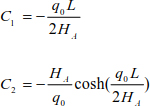
The parabola equation of the curve of the cable is
EXAMPLE 8.4.–
Determine the tension in the cable at points A, B and C solicited by a uniform load q0 = 15 kN/m.L (Figure 8.10).
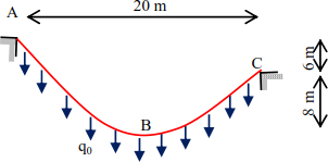
Figure 8.10. Given cable
A calculation reference is associated with point B (Figure 8.11).
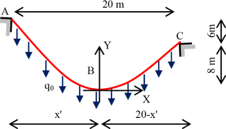
Figure 8.11. Spotting the structure
The parabola equation is given by

Substituting the coordinates of points A and C in the preceding relationship makes it possible to formulate

The accepted solution is x ' =11.39 m.
The system thrust at support A is given as

The tension at point B is (θ = 0) .

We have 

Hence, the tension in the cable at point A is

At point C, we have

Hence θC = 61.71°

The curve equation of the cable can be established using the relationship [8.39] and substituting the expression of thrust HA.
- 2) Inverse method
The expression, given the total length of the cable, is given as
We substitute expression [8.15], and by introducing the deflection in relationship [8.40], we obtain
The relationship [8.41] can be broken down into a Taylor series.

The total length can also be written as

If  , we obtain
The relationship [8.44] allows us to calculate the thrust H using the deflection f, the cable length L and the applied force q0.
EXAMPLE 8.5.–
A flexible cable is attached to points A and B at different levels (Figure 8.12). It is stressed by a uniformly distributed load q0, calculating the total length of the cable and the maximum tension.
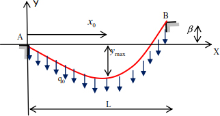
Figure 8.12. Given cable
The successive integration of the deflection of relationship [8.15] makes it possible to write
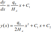
Integration constants can be deduced by

The curve of the cable is

The maximum curve is at the position  and the deflection is

In the relationship HA is assumed to be known, and the maximum deflection ymax can be determined using q0 and L.
8.4.3. Cables subject to any force
In the previous sections, we have presented the analysis of cable structures subjected to concentrated forces and uniformly distributed forces. This analysis can also be conducted for other loads, such as an operating load that can accompany a permanent load. This phenomenon causes a change in the cable’s geometry and possibly a change in the system thrust.
Consider an inextensible cable supported at points A and B and acted upon by any load q(x) (Figure 8.13).
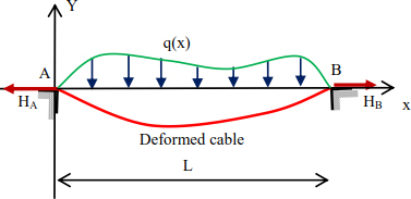
Figure 8.13. Given structure
Applying the relationship [8.40] makes it possible to calculate the total length of the cable in a deformed state.
The slope expression in all sections is
Substituting the relationship [8.46] into the relationship [8.45], the total length is

We deduce the system thrust at support A by
with 
The system thrust [8.48] is deduced using the applied loading. Then, we distinguish the following cases.
Case 1: Concentrated load
The cable (Figure 8.2) takes on a concentrated load P applied at a distance a from support A.

The system thrust can be obtained by substituting the relationship [8.49] into [8.48].

Particularly if  and λ = 1.2, we find HA = 0.774P.
With the inverse method, the thrust is HA = 0.733P. An error of 5.44% is observed between the two calculation methods.
Case 2: Uniformly distributed load
The cable is stressed by a uniformly distributed load q0. In this case, the variation of the tension in the cable is
The system thrust at support A is obtained by substituting relationship [8.51] into [8.48].

Knowing that  , the system thrust becomes

The deflection of the cable is obtained in Example 8.5. It is given by

If the given structure is symmetrical y(  ) = f and β = 0, the deflection is

The system thrust at support A is

8.5. Cables with an inflection point outside the cable
Consider cable (AB) with a length of L0 and attached to points A and B. The cable is funicular, tgθ = 0, located outside the cable at a distance a from the axis (xx). The geometric dimensions are shown in Figure 8.14.
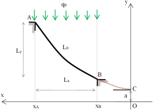
Figure 8.14. Given cable
The distance of the x-axis section from point C following the curve of the cable is

At points A and B, we obtain


The curved length L0 is deduced by
In the same way, the height at the point of the y-axis is
The heights at points A and B are deduced by


The vertical difference between points A and B is
Similarly, the horizontal difference between points A and B may be written as
The relationships [8.59], [8.62] and [8.63] describe the relationship between Lx, Ly and L0. Therefore, for cable geometry Lx, Ly and L0, resolving the equations leads to


The expression of the deflection of the relationship [8.60] is

At the support level, we can write

The forces at points A and B are shown in Figure 8.15.
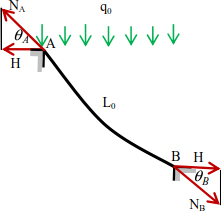
Figure 8.15. Support forces
Combining the relationship [8.68] with [8.69], we obtain the tensions at the supports


EXAMPLE 8.6.–
A cable is stressed by a uniformly distributed load of intensity q0 = 15 N/mL. The geometry is given by Figure 8.16.
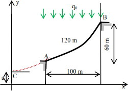
Figure 8.16. Given cable
Calculate the system thrust, the support tensions and deduce the curve of the cable.
The relationship [8.66] allows us to calculate the distance a:
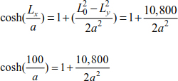
The solution to this equation is a = 130 m.
The x-axis of points A and B are

The slope at support A is

The thrust of the cable is

The expression of support tensions are

The ordinates of the supports can be deduced by

8.6. Suspension bridges
A suspension bridge deck is generally suspended by hangers held by longitudinal cables passing over pulleys at the ends of each pylon and extending to the blocks anchored in the ground (the anchor) (Figure 8.17).

Figure 8.17. Suspension bridge
Suspension bridges are used in small span bridges (river bridge, etc.). The load borne by the cables is made up of the dead weight of the deck and vehicles crossing the suspension bridge. In general, suspension bridge cables bear a load, which is uniformly distributed along the bridge. The shape of the cables in most cases is parabolic.
The cables pass over frictionless pulleys, meaning that the tension in the anchoring cables TA is equal to the tension in the main cables TC at the end of the pylon (Figure 8.18).
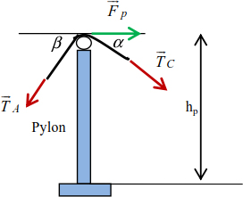
Figure 8.18. Forces on the pulley
In general, the inclination of the anchoring cables β is constant and cannot be equal to that of the cables α. There is a horizontal force at the pulley Fp, which is equivalent to

The mechanical continuity of the cable makes it possible to consider TC = TA; the tension force becomes

This force generates a bending moment along the pylon whose maximum value at the base is

where hp is the height of the pylon.
In addition, the concavity of the cable generates a compression force VP in the pylon equal to

To eliminate the force on the pulley, a roller or cylinder is placed at the end of the pylon (Figure 8.19).

Figure 8.19. Arrangement at the end of the pylon
Knowing that the resulting force due to the effect of the cables is eliminated, the stresses in the cable and the pylon are


EXAMPLE 8.7.–
A cable on a suspension bridge passes over two frictionless pulleys placed at the end of each pylon (Figure 8.20). We assume that the load generated by the deck is 110 kN/mL. We must calculate:
- – the required diameter of the cable;
- – the bending moment in the pylon;
- – the normal force at the base of the pylon;
- – the weight of the anchor block.
The stress limit of the cables is 540 MPa.
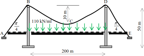
Figure 8.20. Given suspension bridge
The ends of the pylons are at the same level. The tensions in the cable at points B and D are equal and maximum. The maximum tensions in the cable can be deduced by

The resistance condition is

The inclination of the suspension cables from horizontal is

Knowing that 

The maximum bending moment is

The necessary counterweight is

8.7. Conclusion
In this chapter, we have presented the analysis of cables, which are structures working with forces of traction. In general, the funicular shape of the cables depends on the applied load. In this chapter, we described the analysis of cable structures subjected to concentrated and uniformly distributed loads.
The second part of this chapter focused on the analysis of cables with an inflection point located outside the cable, as well as the analysis of suspension bridges. Each chapter is accompanied by examples to clarify the steps taken.
8.8. Problems
Exercise 1
- – Determine the tension in each portion of the following cables.
- – Calculate the thrust of each system.
- – Calculate the inclinations of the cable to the supports.
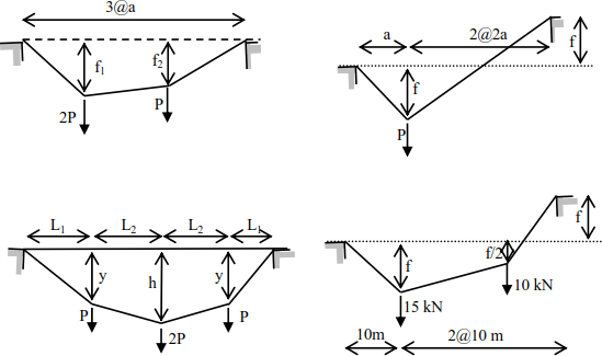
Exercise 2
Using the indirect method, calculate the thrust of each system of cable structures given in Exercise 1 for λ = 1.25.
Exercise 3
For each cable structure,
- – determine the deformation of the cable and deduce the slopes at the supports;
- – draw the diagram of tensions in the cable and deduce its maximum value and specify the corresponding position;
- – calculate the thrust of each system.

Exercise 4
Using the indirect method, calculate the thrust of each system of cable structures given in Exercise 3 for λ = 1.25 .
Exercise 5
Calculate the thrust of each of the following systems:
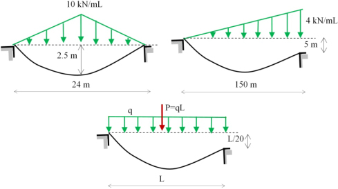
Exercise 6
Calculate the thrust and the expression of tension and deduce the tensions in the supports of the structures in the following cables:
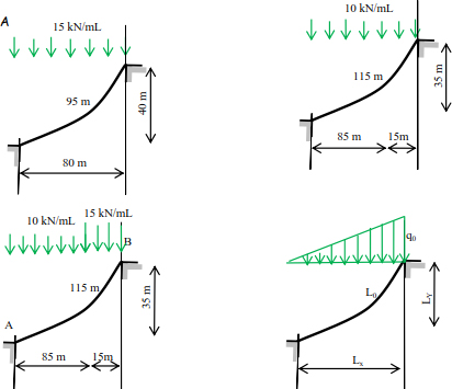
Exercise 7
Analyze the following cable structures. In each case, the cable passes over a frictionless pulley placed at the end of each pylon. Calculate:
- – the required diameter of the cable;
- – the bending moment in the pylon;
- – the normal force at the base of the pylon;
- – the weight of the anchor block.
The stress limit of the cables is 540 MPa.
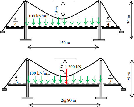
Exercise 8
A cable suspended between two supports with a span of 80 m is stressed by a uniformly distributed load 15 kN/mL. Calculate the minimum deflection at the middle point when the tension in the cable is 900 kN.


