Chapter 5
Parcels
Land development projects often involve the subdivision of large pieces of land into smaller lots. Even if your projects don't directly involve subdivisions, you're often required to show the legal boundaries of your site and the adjoining sites.
Autodesk® AutoCAD® Civil 3D® parcels give you a dynamic way to create, edit, manage, and annotate these legal land divisions. If you edit a parcel object geometry to increase or decrease its size, all of the labels related to the object will reflect the update—including areas, bearings, distances, curve information, and table information.
In this chapter, you will learn to
- Create parcels from objects
- Create a right-of-way parcel using the right-of-way tool
- Create subdivision lots automatically by layout
- Add multiple-parcel segment labels
Introduction to Sites
Before we dig into parcel objects, we have to talk first about the place these are stored, the sites. In Civil 3D, a site represents a collection of parcels, alignments, grading objects, and feature lines that share a common topology. In other words, Civil 3D objects that are in the same site are related to, as well as interact with, one another. The objects that react to one another are called site geometry objects.
Among the objects just listed, the following objects can be placed only in a site:
- Feature lines
- Grading groups
- Parcels
Feature lines and grading groups are discussed in depth in Chapter 14, “Grading.” Alignments, discussed in Chapter 6, can be placed in a site or outside of site.
Think outside of the Lot
The reason for sites is to separate objects of the same type from interacting with each other. For example, you may have a set of parcels that represent impervious areas for drainage calculations. In the same location, you may have an overlay of parcels representing property boundaries. By keeping these items on separate sites, you will be able to keep area information separate.
Dynamic area labels are useful for delineating and analyzing soil boundaries; paving, open space, and wetlands areas; and any other region enclosed with a boundary.
Like all Civil 3D objects, parcels utilize styles. With parcel styles, you can assign different layers, colors, hatch patterns, and other graphical properties to the parcel objects to differentiate between parcel types.
It's important to understand how site geometry objects react to one another. Figure 5.1 shows a typical parcel that might represent a property boundary.
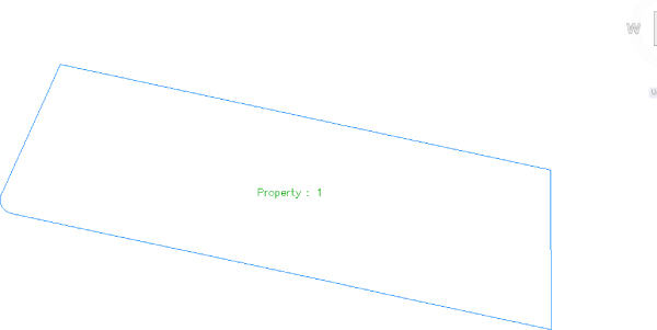
Figure 5.1 A typical property boundary
When an alignment is drawn and placed in the same site as the property boundary, the parcel splits into two parcels, as shown in Figure 5.2.
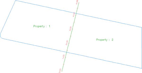
Figure 5.2 An alignment that crosses a parcel divides the parcel in two if the alignment and parcel exist in the same site
You must plan ahead to create meaningful sites based on interactions between the desired objects. For example, if you want a road centerline, a road right-of-way (ROW) parcel, and the lots in a subdivision to react to one another, they need to be in the same site (see Figure 5.3).
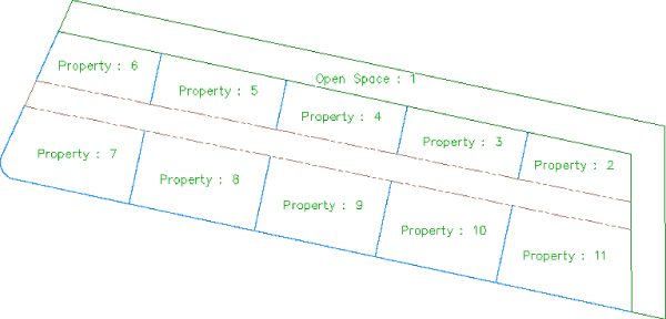
Figure 5.3 ROW parcels, open-space parcels, and subdivision lots react to one another when drawn on the same site.
The alignment (or road centerline), ROW parcel, and lots all relate to one another. A change in the centerline of the road should prompt a change in the ROW parcel and the subdivision lots.
If you'd like to avoid the interaction between site geometry objects, place them in different sites. Figure 5.4 shows an alignment that has been placed in a different site from the boundary parcel. Notice that the alignment doesn't split the boundary parcel.
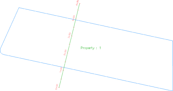
Figure 5.4 An alignment that crosses a parcel won't interact with the parcel if they exist in different sites
It's important that only objects that are intended to react to each other be placed in the same site. For example, in Figure 5.5 you can see parcels representing both subdivision lots and soil boundaries. Because it wouldn't be meaningful for a soil boundary parcel segment to interrupt the area or react to a subdivision lot parcel, the subdivision lot parcels have been placed in a Subdivision Lots site, and the soil boundaries have been placed in a Soil Boundaries site.
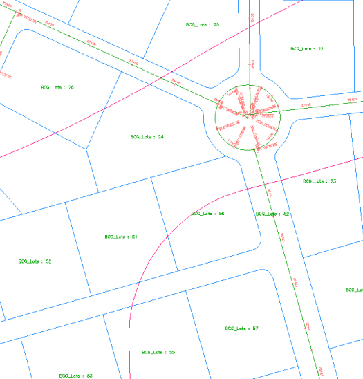
Figure 5.5 Parcels can be used for subdivision lots and soil boundaries as long as they're kept in separate sites.
If you didn't realize the importance of site topology, you might create both your subdivision lot parcels and your soil boundary parcels in the same site and find that your drawing looks similar to Figure 5.6. This figure shows the soil boundary segments dividing and interacting with subdivision lot parcel segments, which doesn't make any sense.
Figure 5.6 Subdivision lots and soil boundaries react inappropriately when placed in the same site.
Another way to avoid site geometry problems is to do site-specific tasks in different drawings and use a combination of external references and data references to share information. For example, you could place soil boundaries in one drawing file and subdivision lots in another drawing file and then use external references to show both drawings together.
You should always consider keeping your legal site plan in its own drawing. Because of the interactive and dynamic nature of Civil 3D parcel objects, it can be quite easy to accidentally modify a parcel segment when you meant to modify a manhole and unintentionally edit a portion of your plat.
You'll see additional examples and drawing divisions later in this chapter, as well as in Chapter 16, “Advanced Workflows.”
If you decide to have sites in the same drawing, here are some sites you may want to create. These suggestions are meant to be used as a starting point. Use them to help find a combination of sites that works for your projects:
- Roads and Lots This site could contain road centerlines, ROWs, platted subdivision lots, open space, adjoining parcels, utility lots, and other aspects of the final legal site plan.
- Grading Feature lines and grading objects are considered part of site geometry. If you're using these tools, you must make at least one site for them. You may even find it useful to have several grading sites.
- Easements If you'd like to use parcels to manage, analyze, and annotate your easements, you may consider creating a separate site for easements.
- Impervious Areas If you'd like to use parcels to manage, analyze, and annotate paved areas, a separate site will be useful. Drainage areas can be tracked using a separate object called a catchment, so there is no need to create a site for drainage areas. You can read more about catchments in the bonus chapter, “Storm and Sewer Analysis,” found on this book's web page, www.sybex.com/go/masteringcivil3d2015.
- Soils Many projects require knowledge of the different soil types present on the site. You will want soils in a separate site so that their boundaries don't interact with other objects in the drawing.
As you learn new ways to take advantage of alignments, parcels, and grading objects, you may find additional sites that you'd like to create at the beginning of a new project.
Creating a New Site
You can create a new site in Prospector. You'll find the process easier if you define the needed sites at the beginning of your project and create those sites right away—or, better yet, have them defined as part of your Civil 3D template. You can always add or delete sites later in the project, if needed.
You can access the Sites collection in Prospector, along with the other Civil 3D objects in your drawing.
The following exercise will lead you through creating a new site that you can use for creating subdivision lots:
- Open the
0501_CreateSite.dwg(0501_CreateSite_METRIC.dwg) file, which you can download from this book's web page at www.sybex.com/go/masteringcivil3d2015.Note that the drawing contains alignments and the boundary for a future parcel, as shown in Figure 5.7.
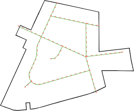
Figure 5.7 The Create Site drawing contains alignments and a boundary parcel.
- On the Prospector tab of Toolspace, go to Sites.
- Right-click the Sites collection, and select New to open the Site Properties dialog.
- On the Information tab of the Site Properties dialog, enter Subdivision Lots for the name of your site.
- Confirm that the settings on the 3D Geometry tab match what is shown in Figure 5.8.
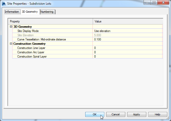
Figure 5.8 Confirm the settings on the 3D Geometry tab.
As you create parcels, Civil 3D will automatically number them for you. The values in the Numbering tab are the starting point.
- Confirm that both values on the Numbering tab are set to 1. Click OK.
- Expand the Sites collection on the Prospector tab of Toolspace, and note that your Subdivision Lots site appears on the list, as shown in Figure 5.9. You can repeat the process for all the sites you anticipate needing over the course of the project.
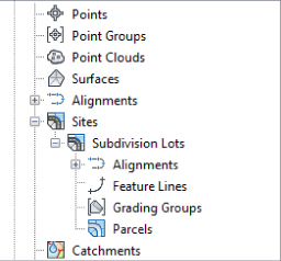
Figure 5.9 Your new site is listed in Prospector.
Please note that you also have the option of creating a new site when a parcel-creation command is issued within the Parcel Layout Tools or when parcels are created from objects.
- Save and close the drawing. If you would like to see what the drawing should look like at this point, you can open
0501_CreateSite_FINISHED.dwg(0501_CreateSite_METRIC_FINISHED.dwg), available from the book's website.
Creating a Boundary Parcel
The Create Parcel From Objects tool allows you to create parcels by choosing AutoCAD entities in your drawing or in an XRef'd drawing. In a typical workflow, it's common to encounter a boundary created by AutoCAD entities, such as polylines, lines, and arcs.
When you're using AutoCAD geometry to create parcels, it's important that the geometry be created carefully and meet certain requirements. The AutoCAD geometry must be lines, arcs, polylines, 3D polylines, or polygons. It can't include blocks, ellipses, circles, or other entities. Civil 3D may allow you to pick objects with an elevation other than zero, but you'll find you get better results if you flatten the objects so all objects have an elevation of zero. Sometimes the geometry appears sound when elevation is applied, but you may notice this isn't the case once the objects are flattened. Flattening all objects before creating parcels can help you prevent frustration when creating parcels.
This exercise will teach you how to create a parcel from Civil 3D objects:
- Open the
0502_CreateBoundary.dwg(0502_CreateBoundary_METRIC.dwg) file, which you can download from this book's web page.This drawing has several alignments, which were created to use no site, and one closed polyline representing a boundary. Your boundary could also be composed of multiple lines and arcs, but for this example we have already defined the boundary as polyline.
- On the Home tab
 Create Design panel, select Parcel Create Parcel From Objects.
 - At the
Select lines, arcs, or polylines to convert into parcels or [Xref]:prompt, pick the polyline that represents the site boundary, and press ↵.The Create Parcels – From Objects dialog appears.
- From the drop-down menus, select Subdivision Lots, Property, and Name Square Foot & Acres (or Name Square Meter & Hectares if you are working in metric units) in the Site, Parcel Style, and Area Label Style selection boxes, respectively.
Leave everything else set to the defaults, as shown in Figure 5.10. Check to make sure that Erase Existing Entities box is checked. This means that the polyline that you selected as a boundary will be deleted upon parcel creation.
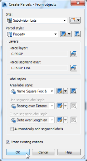
Figure 5.10 Site and style settings for your new boundary parcel
- Click OK to dismiss the dialog. You will notice that a parcel for the boundary has been created.
- Go back to Prospector and expand the Alignments collection. You will notice that all the alignments in the drawing are grouped under the Centerline Alignments category. Right-click that category and select the Move To Site option. Since you have only one site in the drawing, you will be presented with only one option. Leave the selection of alignments as displayed and click OK.
On a side note, you can also select them in Prospector individually or on the screen and then from the context menu select the Move To Site option.
- You will notice that on transferring the alignment objects to the site that has the parcels, these objects interact with the parcel objects, further dividing the initial parcel into a total of six parcels.
- Save and close the drawing. If you would like to see what the drawing should look like at this point, you can open
0502_CreateBoundary_FINISHED.dwg(0502_CreateBoundary_METRIC_FINISHED.dwg), available from the book's website.
The boundary polyline forms parcel segments that react with the alignments. Area labels are placed within the newly created parcels, as shown in Figure 5.11.
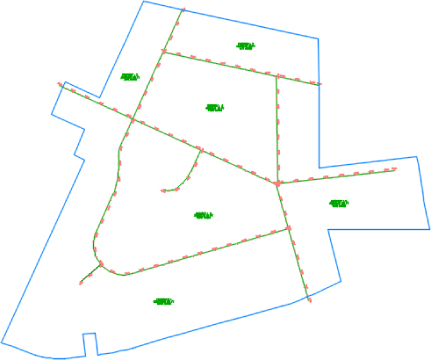
Figure 5.11 The boundary parcel segments, alignments, and area labels
Using Parcel Creation Tools
When you don't have existing lines to work with, the best option is to draw parcel segments using the Parcel Layout tools. Figure 5.12 shows the many commands available to you.
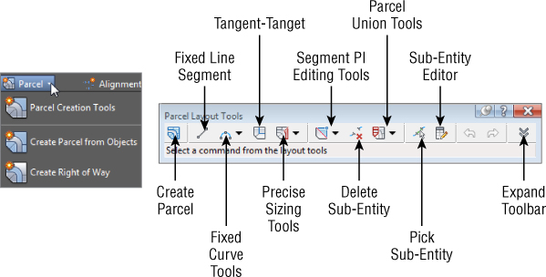
Figure 5.12 Selecting parcel creation tools
Although you may never have thought of things like wetland areas or easements as parcels in the past, you can take advantage of the parcel tools to assist in labeling, stylizing, and analyzing these features for your plans.
This exercise will teach you how to create a parcel representing wetlands using the transparent commands that you got used to in previous chapters and the Draw Tangent-Tangent With No Curves tool from the Parcel Layout Tools toolbox:
- Open the
0503_WetlandsParcel.dwg(0503_WetlandsParcel_METRIC.dwg) file, which you can download from this book's web page.Note that this drawing has several alignments and parcels. For the wetland point data, you will import them from a LandXML file using the tools you learned in Chapter 2, “Survey.”
- Go to the Insert tab and from the Import panel select the LandXML import option. Browse and select to import the file
0503_WetlandParcelData.xml. Click Open, accept the defaults, and click OK. The point data should be imported and ready to be used for parcel definition. - Right-click the Sites node of Prospector and create a new site, Wetlands. Click OK to go to the next step.
 On the Home tab of the ribbon, Create Design Panel, choose Parcel Parcel Creation Tools on the Create Design panel.
The Parcel Layout Tools toolbar appears.
 Click the Draw Tangent-Tangent With No Curves tool on the Parcel Layout Tools toolbar.
The Create Parcels – Layout dialog appears.
- From the drop-down menus, select Wetlands, Wetland, and Name Square Foot & Acres (or Name Square Meter Hectares) in the Site, Parcel Style, and Area Label Style selection boxes, respectively.
Keep the default settings for all other options.
- Click OK.
 At the
 Specify start point:prompt, click the Point Number Transparent command available in the Transparent Commands Toolbar (or type ‘PN ↵ at the command prompt).- At the
Enter Point Number:prompt, enter 1-11,1 ↵.You will see a line form through the wetland boundary points in the northwest corner of the project and immediately form the parcel.
- Press Esc once to exit the Transparent command, and press Esc a second time to complete the parcel.
- Press Enter to start a new lot line. Then repeat steps 8 through 10 for the other wetland points using points 12 through 22, entering 12-22,12 for the transparent point input.
- Press Esc three times to exit the command.
Your drawing should look similar to Figure 5.13.
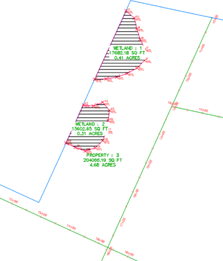
Figure 5.13 The wetlands defined on the site
To illustrate how to change the styles that are in use on a parcel, you will next change the parcel style and the area selection label style.
- Select the northern wetland parcel's area label. From the Parcel contextual tab Modify panel, click the Parcel Properties icon.
The Parcel Properties dialog appears.
- On the Information tab, select Mitigated Wetland from the drop-down menu in the Object Style selection box, and then click Apply to observe the change.
Remain in the Parcel Properties dialog. The parcel hatch pattern will change from a full hatch to one that follows the inside of the parcel perimeter.
- To change the parcel area label style, switch to the Composition tab in the Parcel Properties dialog.
- From the Area Selection Label Style pull-down, select Name Area & Perimeter, and click OK. Press Esc to deselect the parcel.
- Select the south wetland parcel by clicking its area label. From the Parcel contextual tab Modify panel, click Parcel Properties, as you did in step 13.
- In the Composition tab, change the Area Selection Label Style setting to Parcel Name and click OK.
- Save and close the drawing. If you would like to see what the drawing should look like at this point, you can open
0503_WetlandsParcel_FINISHED.dwg(0503_WetlandsParcel_METRIC_FINISHED.dwg), available from the book's website.
Your parcels will look like Figure 5.14.
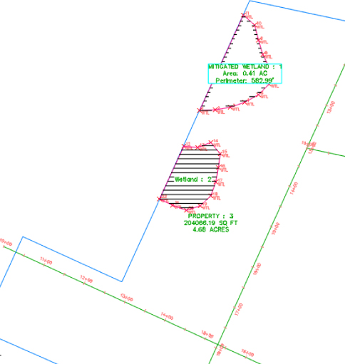
Figure 5.14 The wetlands parcels with the appropriate parcel styles and label styles applied
Creating a Right-of-Way Parcel
The Create ROW tool creates ROW parcels on either side of an alignment based on your specifications. The Create ROW tool can be used only when alignments are placed on the same site as the boundary parcel. The resulting ROW parcel will look similar to Figure 5.15.
Figure 5.15 The resulting parcels after application of the Create ROW tool
The Create ROW tool includes the following options:
- Offset distance from alignment
- Fillet or chamfer cleanup at parcel boundaries
- Alignment intersections
Figure 5.16 shows an example of chamfered cleanup at alignment intersections.
Figure 5.16 A ROW with chamfer cleanup at alignment intersections
Once the ROW parcel is created, it's no different from any other parcel. It should be noted that the ROW parcel doesn't maintain a dynamic relationship with the alignment that created it. A change to the alignment will require the ROW parcel to be edited or, more likely, re-created.
This exercise teaches you how to use the Create ROW tool to automatically place a ROW parcel for each alignment on your site:
- Open the
0504_CreateROWParcel.dwg(0504_CreateROWParcel_METRIC.dwg) file, which you can download from this book's web page.Note that this drawing has some alignments on the same site as the boundary parcel, resulting in several smaller parcels between the alignments and boundary.
- On the Home tab Create Design panel, choose Parcel Create Right Of Way.
- At the
Select parcels:prompt, pick all existing parcels by selecting each of their area labels. On selection feedback is provided through a change in the way the selected parcels display. - Press ↵ to stop picking parcels.
The Create Right Of Way dialog appears.
- Expand the Create Parcel Right Of Way branch, and enter 22.5’ (7 m) as the value for Offset From Alignment.
- Expand the Cleanup At Parcel Boundaries branch.
- Change the Cleanup Method setting to None.
- Expand the Cleanup At Alignment Intersections branch.
- Enter 25′ (8 m) as the value for Fillet Radius At Alignment Intersections.
- Select Fillet from the drop-down menu in the Cleanup Method selection box. Verify that the Create Right Of Way dialog matches Figure 5.17.

Figure 5.17 The Create Right Of Way dialog
- Click OK to dismiss the dialog and create the ROW parcels. Exit the command by pressing Esc.
- Save the drawing but keep it open for the next exercise. If you would like to see what the drawing should look like at this point, you can open
0504_CreateROWParcel_FINISHED.dwg(0504_CreateROWParcel_METRIC_FINISHED.dwg), available from the book's website.Your drawing should look similar to Figure 5.18.
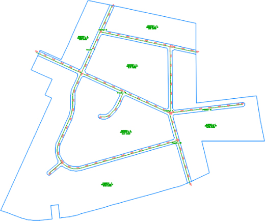
Figure 5.18 The completed ROW parcels
Adding a Cul-de-Sac Parcel
In this section you will add a cul-de-sac at the end of ROAD G and one at the end of the ROAD H alignment layout. Although drawing the cul-de-sac requires only basic drafting techniques, there are numerous steps. To save time, a block will be provided so that you don't have to draw it yourself. After inserting this block, you will convert its components into a parcel. This exercise also introduces some editing tools.
You will need to have completed the previous exercise before continuing or open the FINISHED version of the drawing.
- Continue working in the drawing from the previous exercise or open
0504_CreateROWParcel_FINISHED.dwg(0504_CreateROWParcel_METRIC_FINISHED.dwg), available on the book's website. - Locate
0504_CulDeSac.dwg(0504_CulDeSac_METRIC.dwg) in the chapter's directory and insert the file using the settings shown in Figure 5.19.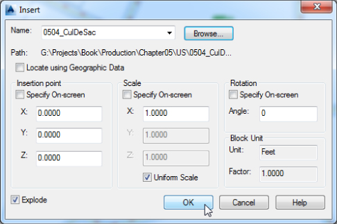
Figure 5.19 Inserting the cul-de-sac block
 From the Home tab Create Design panel, expand Parcel Create Parcel From Objects.
- At the
Select lines, arcs, or polylines to convert into parcels or [Xref]:prompt, select the two polylines that represent the outside of the cul-de-sac and press ↵. - In the Create Parcels – From Objects dialog, verify the following settings:
- Site is set to Subdivision Lots.
- Parcel Style is set to Property.
- Area Label Style is set to Name Square Foot & Acres (Name Square Meter & Hectares).
- Erase Existing Entities is checked.
- Click OK.
Your drawing should look similar to Figure 5.20.
Figure 5.20 The cul-de-sac turned into a parcel
Both cul-de-sacs are now defined as parcels, but there are some extra lines that need to be taken care of. Let's see how to clean this up a bit.
- Change the drawing scale to 1″ = 20′ (1:250). This will cause the parcel area labels to scale down, making the next few steps easier.
- From the Home tab Create Design panel, expand Parcel Parcel Creation Tools.
 The Parcel Layout Tools toolbar opens.
 - Select the Delete Sub-Entity tool.
- At the
Select subentity to remove:prompt, select the right of way that interferes with the cul-de-sac, as shown in Figure 5.21. Apply the selected edits to both cul-de-sacs.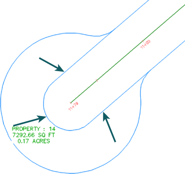
Figure 5.21 Delete these parcel segments.
- Press Esc twice to exit the command.
- Save and close the drawing. If you would like to see what the drawing should look like at this point, you can open
0504_CreateROWParcelsCDS_FINISHED.dwg(0504_CreateROWParcelsCDS_METRIC_FINISHED.dwg), available from the book's website.
Your cul-de-sacs are complete, as shown in Figure 5.22.
Figure 5.22 The finished cul-de-sacs
Creating Subdivision Lot Parcels Using Precise Sizing Tools
The precise sizing tools allow you to create parcels to your exact specifications. You'll find these tools most useful when you have your roadways established and understand your lot-depth requirements. These tools provide automatic, semiautomatic, and freeform ways to control the parcel sizing using frontage, parcel area, and segment direction.
Attached Parcel Segments
Before learning about the parcel sizing tools themselves, let's discuss attached parcel segments. Parcel segments created with the precise sizing tools are called attached segments. Attached parcel segments have a start point that is attached to a frontage segment and an endpoint that is defined by the next parcel segment they encounter. Attached segments can be identified by their distinctive diamond-shaped grip at their start point and no grip at their endpoint (see Figure 5.23).
Figure 5.23 A series of attached parcel segments, with their endpoints at the front lot line
In other words, you establish their start point and their direction, but they seek another parcel segment to establish their endpoint. Figure 5.23 shows a series of attached parcel segments. You can tell the difference between their start points and endpoints because the start points have the diamond-shaped grips.
You can drag the diamond-shaped grip along the frontage to a new location and the parcel segment will maintain its angle from the frontage. If the rear lot line is moved or erased, the attached parcel segments find a new endpoint (see Figure 5.24) at the next available parcel segment.
Figure 5.24 The endpoints of attached parcel segments extend to the next available parcel segment if the initial parcel segment is erased.
Parcel Sizing Settings
Before using the precise parcel sizing tools, you should understand that a number of settings affect the behavior of these tools. These settings are found by expanding the Parcel Layout Tools toolbar, as shown in Figure 5.25. Each of these settings is discussed in detail in the following sections.
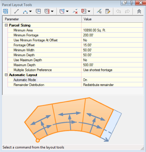
Figure 5.25 Automated sizing options on the expanded Parcel Layout Tools toolbar
Parcel Sizing
 When you create new parcels, the tools respect your default area and minimum frontage (measured from either a ROW or a building setback line). The program always uses these numbers as a minimum; it bases the actual lot size on a combination of the geometry constraints (lot depth, frontage curves, and so on) and the additional settings that follow. Keep in mind that the numbers you establish under the Parcel Sizing option must make geometric sense. For example, if you'd like a series of 7,500-square-foot (700-square-meter) lots that have 100″ (30 m) of frontage, you must make sure that your rear parcel segment allows for at least 75″ (23 m) of depth; otherwise, you may wind up with much larger frontage values than you desire or a situation where the software can't return a meaningful result.
Automatic Layout
Automatic Layout has two parameters when the list is expanded: Automatic Mode and Remainder Distribution. The Automatic Mode parameter can have the following values:
- On Automatically follows your settings and puts in all the parcels, without prompting you to confirm each one.
- Off Allows you to confirm each parcel as it's created. In other words, this option provides you with a way to semi-automatically create parcels.
The Remainder Distribution parameter tells Civil 3D how you'd like “extra” land handled. This parameter has the following options:
- Create Parcel From Remainder Makes a last parcel with “the leftovers” once the tool has made as many parcels as it can based on the settings in this dialog. This parcel is usually smaller than the other parcels.
- Place Remainder In Last Parcel Adds the leftover area to the last parcel once the tool has made as many parcels as it can based on the settings in this dialog.
- Redistribute Remainder Takes the leftover area and distributes it across all the default-sized parcels once the tool has made as many parcels as it can based on the settings in this dialog. The resulting lots aren't always evenly sized because of differences in geometry around curves and other variables, but the leftover area is absorbed.
There aren't any rules per se in a typical subdivision workflow. Usually the goal is to create as many parcels as possible within the limits of available land. To that end, you'll use a combination of AutoCAD tools and Civil 3D tools to divide and conquer the particular tract of land with which you are working.
Parcel Sizing Tools
The precise sizing tools consist of the Slide Line, Swing Line, and Free Form Create tools (see Figure 5.26).
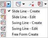
Figure 5.26 The precise parcel sizing tools
Slide Line – Create Tool
The Slide Line – Create tool creates an attached parcel segment based on an angle from frontage. You may find this tool most useful when your jurisdiction requires a uniform lot-line angle from the right of way.
This exercise will lead you through using the Slide Line – Create tool to create a series of subdivision lots:
- Open the
0505_CreateSlide.dwg(0505_CreateSlide_METRIC.dwg) file, which you can download from this book's web page.Note that this drawing has several alignments on the same site as the boundary parcel, resulting in several smaller parcels between the alignments and boundary.
- From the Home tab Create Design panel, expand Parcel Parcel Creation Tools.
 The Parcel Layout Tools toolbar appears.
 - Expand the toolbar by clicking the expansion chevron located at the end of the toolbar .
- In the Parcel Sizing section, change the value of the following parameters by clicking in the Value column and typing in the new values if they aren't already set. Notice how the preview window changes to accommodate your preferences:
- Minimum Area: 10890.00 sq. ft. (1,012 m2)
- Minimum Frontage: 180.000’ (54.75 m)
- Use Minimum Frontage At Offset: No
- Frontage Offset: 25.000’ (10 m)
- Minimum Width: 75.000’ (25 m)
- Minimum Depth: 50.000’ (15 m)
- Use Maximum Depth: No
- Maximum Depth: (leave default value since this will not be used)
- Multiple Solution Preference: Use Shortest Frontage
- In the Automatic Layout section, change the following parameters by clicking in the Value column and selecting the appropriate option from the drop-down menu, if it isn't already set:
- Automatic Mode: On
- Remainder Distribution: Redistribute Remainder
 Click the Slide Line – Create tool. The Create Parcels – Layout dialog appears.
- From the drop-down menus, select Subdivision Lots, Property, and Name Square Foot & Acres (Name Square Meter & Hectares) in the Site, Parcel Style, and Area Label Style selection boxes, respectively.
Leave the rest of the options set to their defaults.
- Click OK to dismiss the dialog.
- At the
Select parcel to be subdivided or [Pick]:prompt, click the PROPERTY : 1 area label. - At the
Select start point on frontage:prompt, use your Endpoint Osnap to pick the point of curvature along the ROW parcel segment for Property : 1 (see Figure 5.27). The point will show with the Osnap marker over it.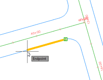
Figure 5.27 Pick the point of curvature along the ROW parcel segment highlighted by the Osnap marker.
The parcel jig appears.
- Move your mouse slowly along the ROW parcel segment, and notice that the parcel jig follows the parcel segment.
- At the
Select end point on frontage:prompt, use your Endpoint Osnap to pick the point of curvature along the ROW parcel segment for Property : 1 (see Figure 5.28).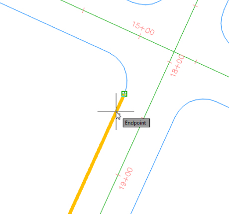
Figure 5.28 Allow the parcel-creation jig to follow the parcel segment, and then pick the point of curvature along the ROW parcel segment highlighted by the Osnap marker.
- At the
Specify angle or [Bearing/aZimuth]:prompt, enter 90 ↵.Notice the preview (see Figure 5.29).
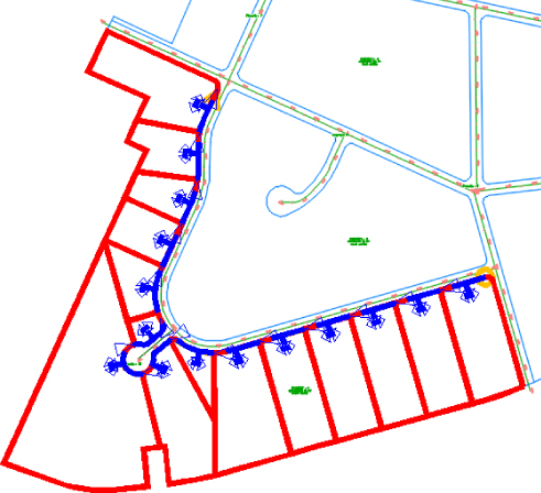
Figure 5.29 A preview of the results of the automatic parcel layout
- At the
Accept result? [Yes/No] <Yes>:prompt, press ↵ to accept the default, Yes. - At the
Select parcel to be subdivided or [Pick]:prompt, press ↵. - Click the X to close the Parcel Layout Tools toolbar.
Your drawing should look similar to Figure 5.30.
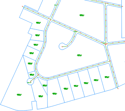
Figure 5.30 The automatically created lots
- Save and close the drawing. If you would like to see what the drawing should look like at this point, you can open
0505_CreateSlide_FINISHED.dwg(0505_CreateSlide_METRIC_FINISHED.dwg), available from the book's website.
Swing Line – Create Tool
The Swing Line – Create tool creates a “backward” attached parcel segment where the diamond-shaped grip appears not at the frontage but at a different location that you specify. The tool respects your minimum frontage, and it adjusts the frontage so it is larger, if necessary, in order to respect your default area. The Swing Line – Create tool is semiautomatic because it requires your input for the swing point location.
You may find this tool most useful around a cul-de-sac or in odd-shaped corners where you must hold frontage but have a lot of flexibility in the rear of the lot.
This exercise will lead you through using the Swing Line – Create tool to create lots:
- Open the
0506_CreateSwing.dwg(0506_CreateSwing_METRIC.dwg) file, which you can download from this book's web page. - From the Home tab Create Design panel, expand Parcel Parcel Creation Tools.
The Parcel Layout Tools toolbar appears.
- Expand the toolbar by clicking the expansion chevron located at the end of the toolbar.
- In the Parcel Sizing section, change the value of the following parameters by clicking in the Value column and typing in the new values if they aren't already set. Notice how the preview window changes to accommodate your preferences:
- Minimum Area: 10890.00 sq. ft. (1,012 m2)
- Minimum Frontage: 180.000’ (54.75 m)
- Use Minimum Frontage At Offset: No
- Frontage Offset: 25.000’ (10 m)
- Minimum Width: 75.000’ (25 m)
- Minimum Depth: 50.000’ (15 m)
- Use Maximum Depth: No
- Maximum Depth: (leave default value since this will not be used)
- Multiple Solution Preference: Use Shortest Frontage
- In the Automatic Layout section, change the following parameters by clicking in the Value column and selecting the appropriate option from the drop-down menu, if it isn't already set:
- Automatic Mode: On
- Remainder Distribution: Redistribute Remainder
 Click the Swing Line – Create tool. The Create Parcels – Layout dialog appears.
- From the drop-down menus, select Subdivision Lots, Property, and Name Square Foot & Acres (Name Square Meter & Hectares) in the Site, Parcel Style, and Area Label Style selection boxes, respectively.
Leave the rest of the options set to their defaults.
- Click OK to dismiss the dialog.
- At the
Select parcel to be subdivided or [Pick]:prompt, click the Property : 22 area label. - At the
Select start point on frontage:prompt, use your Endpoint Osnap to pick the point on the curve along the ROW parcel segment for Property : 22 on its southeast corner (see Figure 5.31). The point will show with the Osnap marker over it.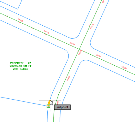
Figure 5.31 Pick the point on the curve on the parcel's southeast corner, as highlighted by the Osnap marker along the ROW parcel segment.
The parcel jig appears.
- Move your mouse slowly along the ROW parcel segment, and notice that the parcel jig follows the parcel segment.
- At the
Select end point on frontage:prompt, use your Endpoint Osnap to pick the end point along the ROW parcel segment for Property : 22 on its northwest corner (see Figure 5.32)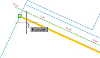
Figure 5.32 Allow the parcel-creation jig to follow the parcel segment, and then pick the end point as highlighted by the Osnap marker on the ROW parcel segment.
- At the
Specify swing pointprompt, select the interior corner of the parcel, as shown in Figure 5.33, and highlighted by the Osnap marker.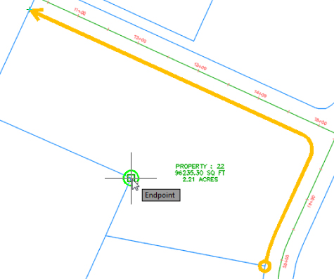
Figure 5.33 Swing point selection
- At the
Accept result? [Yes/No] <Yes>:prompt, press ↵ to accept the default, Yes. - At the
Select parcel to be subdivided or [Pick]:prompt, press ↵. - Click the X to close the Parcel Layout Tools toolbar.
Your drawing should look similar to Figure 5.34.
Figure 5.34 The automatically created lots
- Save and close the drawing. If you would like to see what the drawing should look like at this point, you can open
0506_CreateSwing_FINISHED.dwg(0506_CreateSwing_METRIC_FINISHED.dwg), available from the book's website.
Free Form Create Tool
A site plan is more than just single-family lots. Areas are usually dedicated for open space, stormwater-management facilities, parks, and public utility lots. The Free Form Create tool can be useful when you're creating these types of parcels. This tool, like the precise sizing tools, creates an attached parcel segment with the special diamond-shaped grips.
In the following exercise, you'll use the Free Form Create tool to create a new parcel:
- Open the
0507_CreateFreeForm.dwg(0507_CreateFreeForm_METRIC.dwg) file.Note that this drawing contains a series of subdivision lots.
- Zoom to Property : 18.
- Use the AutoCAD Erase command to delete the parcel lines highlighted in Figure 5.35.
Figure 5.35 Delete the highlighted parcel lines.
Because the order in which the parcel segments are erased will determine the parcel numbers, your parcel numbers may vary from those created by the authors.
The parcels readjust but the resulting lot is now much larger than needed. Let's add a line using the Free Form Create tool. You will explore deleting parcel lines in more depth later in this chapter.
 From the Home tab Create Design panel, select Parcel Parcel Creation Tools.
- On the Parcel Layout Tools toolbar, select the Free Form Create tool.
The Create Parcels – Layout dialog appears.
- Select Subdivision Lots, Property and Name Square Foot & Acres (Name Square Meter & Hectares) from the drop-down menus in the Site, Parcel Style, and Area Label Style selection boxes, respectively.
Keep the default values for the remaining options.
- Click OK to dismiss the dialog.
- Slide the Free Form Create attachment point along the frontage of the Property : 18 area.
- At the
Select attachment point:prompt, pick near the point shown in Figure 5.36.
Figure 5.36 Use the Free Form Create tool to select an attachment point.
- At the
Specify lot line direction:(ENTER for perpendicular) or [Bearing/aZimuth]:prompt, press ↵ to specify a perpendicular lot line direction.A new parcel segment is created perpendicular to the ROW parcel segment, as shown in Figure 5.37 (your resulting lot numbers may differ). Note that a new lot parcel has formed.
Figure 5.37 A new parcel created using the Free Form Create tool
Although most parcel lines are created perpendicular to the right-of-way line, please note that you can use the Free Form Create tool to attach a new parcel segment to any parcel segment in the drawing.
- Press ↵ to exit the Free Form Create command.
- Click the X or press Esc to exit the Parcel Layout Tools toolbar.
- Pick the new parcel segment so that you see its diamond-shaped grip.
- Grab the grip, and slide the segment along the ROW parcel segment (see Figure 5.38).
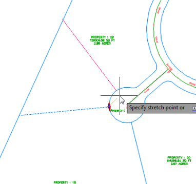
Figure 5.38 Sliding an attached parcel segment
Notice that when you place the parcel segment at a new location, the segment endpoint snaps back to the rear parcel segment. This is typical behavior for an attached parcel segment.
- Save and close the drawing. If you would like to see what the drawing should look like at this point, you can open
0507_CreateFreeForm_FINISHED.dwg(0507_CreateFreeForm_METRIC_FINISHED.dwg), available from the book's website.
Editing Parcels by Deleting Parcel Segments
One of the most powerful aspects of Civil 3D parcels is the ability to perform many iterations of a site plan design. Typically, this design process involves creating a series of parcels and then deleting them to make room for iterations with different parameters or deleting certain segments to make room for easements, public utility lots, and more.
You can delete parcel segments using the AutoCAD Erase tool as shown in the previous exercise, or you can use the Delete Sub-Entity tool on the Parcel Layout Tools toolbar, a tool you used in the cleanup of the cul-de-sac exercise.
It's important to understand the difference between these two methods. The AutoCAD Erase tool behaves as follows:
- If a series of parcel segments was originally created from a polyline (or similar parcel layout tools, such as the Tangent-Tangent With No Curves tool), the AutoCAD Erase tool erases the entire series of segments (see Figure 5.39).
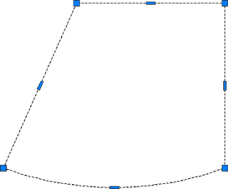
Figure 5.39 The highlighted segments will be erased after using the AutoCAD Erase tool.
- If a series of parcel segments was originally created using lines or arcs (or similar parcel layout tools, such as the precise sizing tools), then AutoCAD Erase erases each segment individually (see Figure 5.40).
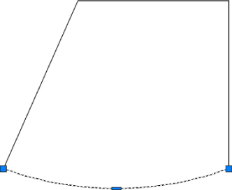
Figure 5.40 The highlighted segment will be erased.
The Delete Sub-Entity tool acts more like the AutoCAD Trim tool. The Delete Sub-Entity tool erases only the parcel segments between parcel vertices. For example, if Parcel # 69, as shown in Figure 5.41, must be absorbed into Parcel # 23 based on the fact that the parcel changes ownership, you'd want to erase only the segment on the east of Parcel # 23 and not the entire segment shown previously in Figure 5.40. If you look at the Parcel #23, you will notice that is made up of a series of segments. If we had tried to use the AutoCAD Erase command, then the whole series would have been deleted, but since we want only the east segment, then the Delete Sub-Entity tool will accomplish that.
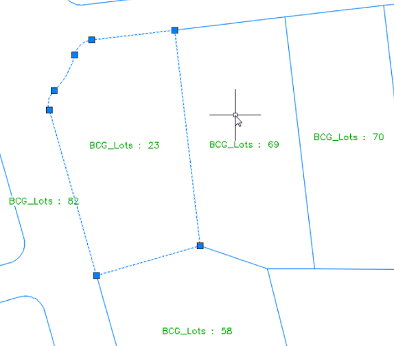
Figure 5.41 Using the Delete Sub-Entity tool to erase the east parcel segment for Parcel # 23
As an alternative to launching the Parcel Creation tools by choosing the Home tab ![]() Create Ground Data panel
Create Ground Data panel ![]() Parcel
Parcel ![]() Parcel Creation Tools, you can access them by selecting the area label of a parcel and then, from the Parcel contextual tab
Parcel Creation Tools, you can access them by selecting the area label of a parcel and then, from the Parcel contextual tab ![]() Modify panel, selecting Parcel Layout Tools. Figure 5.42 shows the result of this deletion.
Modify panel, selecting Parcel Layout Tools. Figure 5.42 shows the result of this deletion.
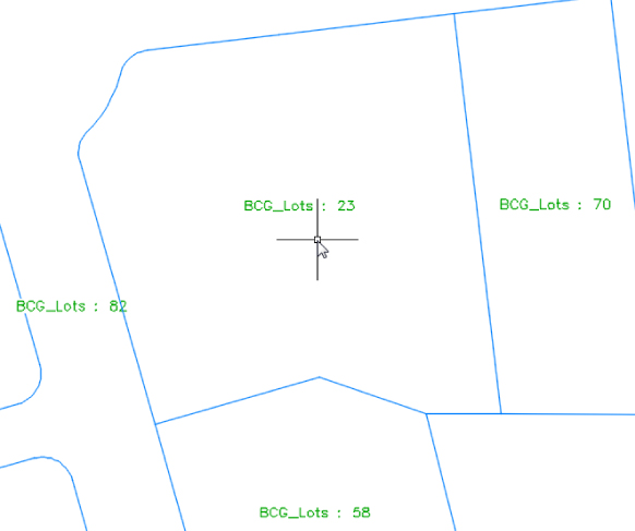
Figure 5.42 The east lot line for Parcel # 23 was erased using the Delete Sub-Entity tool, thus enlarging this parcel with the new addition.
Best Practices for Parcel Creation
Now that you have an understanding of how objects in a site interact and you've had some practice creating and editing parcels in a variety of ways, we'll take a deeper look at how parcels must be constructed to achieve topology stability, predictable labeling, and desired parcel interaction.
Forming Parcels from Segments
Earlier in this chapter, you saw that parcels are created only when parcel segments form a closed area (see Figure 5.43).
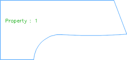
Figure 5.43 A parcel is created when parcel segments form a closed area.
Parcels must always close. Whether you draw AutoCAD lines and use the Create Parcel From Objects menu command or use the parcel segment creation tools, a parcel won't form until there is an enclosed polygon. Figure 5.44 shows four parcel segments that don't close; therefore, no parcel has been formed.
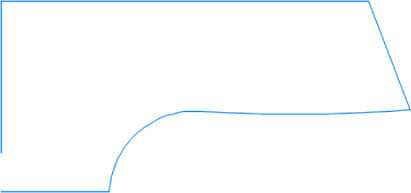
Figure 5.44 No parcel will be formed if parcel segments don't completely enclose an area.
There are times in surveying and engineering when parcels of land don't necessarily close when created from legal descriptions. In this case, you must work with your surveyor to perform an adjustment or find some other solution to create a closed polygon.
You also saw that even though parcels can't be erased, if you erase the appropriate parcel segments, the area contained within a parcel is assimilated into neighboring parcels. Remember that you can delete parcels if you move them to a new site and delete that site. This is an easy way to delete those parcels that are not needed in the drawing.
Parcels Reacting to Site Objects
Parcels require only one parcel segment to divide them from their neighbor (see Figure 5.45). This behavior eliminates the need for duplicate segments between parcels, and duplicate segments must be avoided.
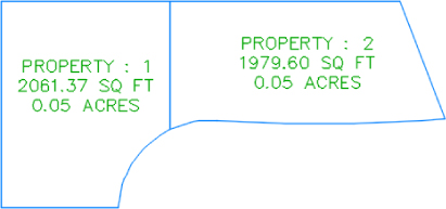
Figure 5.45 Two parcels, with one parcel segment between them
As you saw in the section on site interaction, parcels understand their relationships to one another. When you create a single parcel segment between two subdivision lots, you have the ability to move one line and affect two parcels. Figure 5.46 shows the moved parcel segment from Figure 5.45 once the parcel segment between them has been shifted to the right. Note that both areas change in response.
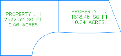
Figure 5.46 Moving one parcel segment affects the area of two parcels.
A mistake that many people new to Civil 3D make is to create parcels from closed polylines, which results in a duplicate segment between parcels. Figure 5.47 shows two parcels created from two closed polylines. These two parcels may appear identical to the two seen in the previous example, because they were both created from a closed polyline rectangle; however, the segment between them is actually two segments. You can notice that in the figure when the Selection Cycling toggle (Ctrl+W) is enabled.
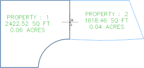
Figure 5.47 Adjacent parcels created from closed polylines create overlapping or duplicate segments.
The duplicate segment becomes apparent when you attempt to grip-edit the parcel segments. Moving one vertex from the common lot line, as shown in Figure 5.48, reveals the second segment. Also note that a sliver parcel is formed. Duplicate site geometry objects and sliver parcels make it difficult for Civil 3D to solve the site topology and can cause unexpected parcel behavior.
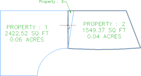
Figure 5.48 Duplicate segments become apparent when they're grip-edited and a sliver parcel is formed.
Creating a subdivision plat of parcels this way almost guarantees that your labeling won't perform properly and could lead to inaccurate data.
Parcels form to fill the space contained by the original outer boundary. You should always begin a parcel-division project with an outer boundary of some sort (see Figure 5.49).
Figure 5.49 An outer boundary parcel with alignments that are not part of any site.
You can then move road centerline alignments to the site, which divides the outer boundary parcel, as shown in Figure 5.50.

Figure 5.50 Alignments moved to the same site as the boundary parcel divide the boundary parcel.
It's important to note that the boundary parcel no longer exists intact. As you subdivide this site, Parcel 1 is continually reallocated with every division. As road ROW and subdivision lots are formed from parcel segments, more parcels are created. Every bit of space that was contained in the original outer boundary is accounted for in the mesh of newly formed parcels (see Figure 5.51).
Figure 5.51 The total area of parcels contained within the original boundary is equal to the original boundary area.
From now on, you'll consider ROW, wetlands, parkland, and open space areas as parcels, even if you didn't before. You can make custom label styles to annotate these parcels however you like, including a “no show” or none area label.
Constructing Parcel Segments with the Appropriate Vertices
Parcel segments should have natural vertices only where necessary and split-created vertices at all other intersections. A natural vertex, or point of intersection (PI), can be identified by picking a line, polyline, or parcel segment and noting the location of the grips (see Figure 5.52).
Figure 5.52 Natural vertices on a parcel segment
A split-created vertex occurs when two parcel segments touch or cross each other. Note that in Figure 5.53, the parcel segment doesn't show a grip even where each individual lot line touches the ROW parcel.
Figure 5.53 Split-created vertices on a parcel segment
It's desirable to have as few natural vertices as possible. In the example shown in Figure 5.53, the ROW frontage line can be expressed as a single bearing and length from the end of the arc through the beginning of the next arc, as opposed to having several smaller line segments.
If the foundation geometry is drawn with a natural vertex at each lot line intersection, the resulting parcel segment won't label properly and may cause complications with editing and other functions. This subject will be discussed in more detail in the section “Labeling Spanning Segments” later in this chapter.
Parcel segments must not overhang. Spanning labels are designed to overlook the location of intersection-formed (or T-shaped) split-created vertices. However, these labels won't span a crossing-formed (X- or + [plus]-shaped) split-created vertex. Even a very small parcel segment overhang will prevent a spanning label from working and may even affect the area computation for adjacent parcels. The overhanging segment in Figure 5.54 would prevent a label from returning the full spanning length of the ROW segment it crosses.
Figure 5.54 Overhanging segment
Labeling Parcel Areas
A parcel area label is placed at the parcel centroid by default, and it refers to the parcel in its entirety. It doesn't necessarily have to include the actual area of the parcel. When asked to pick a parcel, you pick the area label; however, this behavior is valid only for Civil 3D commands. For example, if you pick a parcel area label and invoke the AutoCAD Erase command, the parcel will not be erased.
Area labels can be customized to suit your needs. Figure 5.55 shows a variety of customized area labels.
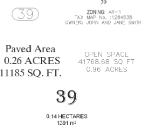
Figure 5.55 Sample area labels
Area labels often include the parcel name or number, and often the names and/or numbers need to be changed after the parcels are placed in the drawing. To accomplish this, you can select a parcel and then on the Parcel contextual tab ![]() Modify panel choose Renumber/Rename.
Modify panel choose Renumber/Rename.
The following exercise will teach you how to renumber a series of parcels:
- Open
0508_RenumberParcels.dwg(0508_RenumberParcels_METRIC.dwg). Note that this drawing already contains some subdivision lot parcels.  Near the southeast corner of the project, select Property : 13. On the Parcel contextual tab Modify panel, select Renumber/Rename. The Renumber/Rename Parcels dialog appears.
- In the Renumber/Rename Parcels dialog, make sure Subdivision Lots is selected from the drop-down menu in the Site selection box and that the Renumber radio button is selected. Change the value of the Starting Number selection box to 100. Click OK.
- At the
Specify start point or [Polylines/Site]:prompt, pick a point on the screen anywhere inside the Property : 13 parcel, which will become your new Property: 100 parcel at the end of the command. - At the
End point or [Undo]:prompt, pick a point on the screen anywhere inside the Property : 18 parcel, almost as if you were drawing a line; then pick a point inside Property : 22 and end by picking a point inside the Property : 27. Press ↵ to complete choosing parcels. Press ↵ again to end the command.Note that your parcels have been renumbered from 100 through 114.
- Save the drawing but keep it open for the next exercise. If you would like to see what the drawing should look like at this point, you can open
0508_RenumberParcels_FINISHED.dwg(0508_RenumberParcels_METRIC_FINISHED.dwg), available from the book's website.
The next exercise will lead you through one method of changing an area label using the Edit Parcel Properties dialog:
- Continue working in the
0508_RenumberParcels.dwg(0508_RenumberParcels_METRIC.dwg) file, or you can open0508_RenumberParcels_FINISHED.dwg(0508_RenumberParcels_METRIC_FINISHED.dwg), available from the book's website.  Select Property : 100 and then on the Parcel contextual tab Modify panel, select Multiple Parcel Properties.
- At the
Specify start point or [Polylines/All/Site]:prompt, pick a point on the screen inside of Property : 100 close to the middle of the parcel. - At the
End point or [Undo]:prompt, pick a point on the screen inside Property : 107 close to the middle of this parcel; then end by clicking inside Property: 108 close to the middle of this parcel using the same technique that you used in steps 4 and 5 of the previous exercise. This line should cross sequentially only parcels 100–108. - Press ↵ to complete parcel selection, and press ↵ again to open the Edit Parcel Properties dialog.
- In the Area Selection Label Style portion of the Edit Parcel Properties dialog, use the drop-down menu to select the Parcel Number area label style, as shown in Figure 5.56.
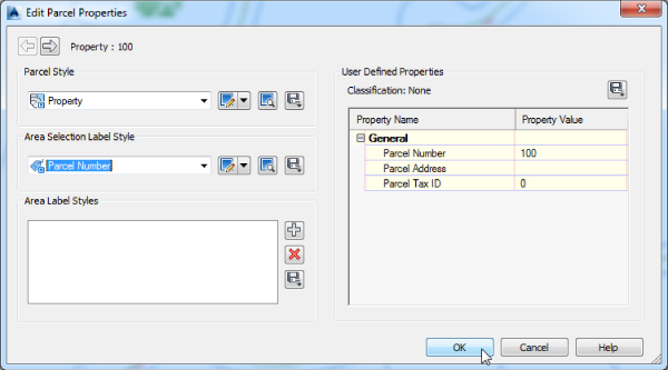
Figure 5.56 The Edit Parcel Properties dialog
 Click the Apply To All Parcels button to the right of the Parcel Number listing.
- Click Yes in the dialog displaying the question “Apply the area selection label style to the 9 selected parcels?”
- Click OK to exit the Edit Parcel Properties dialog.
The nine parcels now have parcel area labels that call out numbers only. Note that you could also use this interface to add a second area label to certain parcels by clicking the plus sign in the Area Label Styles section of the Edit Parcel Properties dialog.
- Save the drawing but keep it open for the next exercise. If you would like to see what the drawing should look like at this point, you can open
0508_ChangeMultipleLabels_FINISHED.dwg(0508_ChangeMultipleLabels_METRIC_FINISHED.dwg), available from the book's website.
This section's final exercise will show you how to use Prospector to change a group of parcel area labels at the same time:
- Continue working in the previous file or open the
0508_ChangeMultipleLabels_FINISHED.dwg(0508_ChangeMultipleLabels_METRIC_FINISHED.dwg) file, available on the book's website. - In Prospector, expand Sites Subdivision Lots and select the Parcels collection.
- In the expanded listing hold down the Ctrl key, and select all of the lots from Property : 109 to Property : 114.
- Release the Ctrl key, and your parcels should remain selected.
- Slide over to the Area Label Style column, right-click the column header, and select Edit (see Figure 5.57).

Figure 5.57 Right-click the Area Label Style column header and select Edit.
- In the Select Label Style dialog, select Parcel Name from the drop-down menu in the Label Style selection box.
- Click OK to dismiss the dialog.
The drawing will process for a moment.
- Once the processing is finished, minimize Prospector and inspect your parcels.
All the selected parcels should now have the Parcel Name area label style.
- Save and close the drawing. If you would like to see what the drawing should look like at this point, you can open
0508_ChangeAreaLabel_FINISHED.dwg(0508_ChangeAreaLabel_METRIC_FINISHED.dwg), available from the book's website.
Labeling Parcel Segments
Although parcels are used for much more than just subdivision lots, most parcels you create will probably be used for concept plans, record plats, and other legal subdivision plans. These plans, such as the one shown in Figure 5.58, almost always require segment labels for bearing, distance, direction, crow's feet, and more.
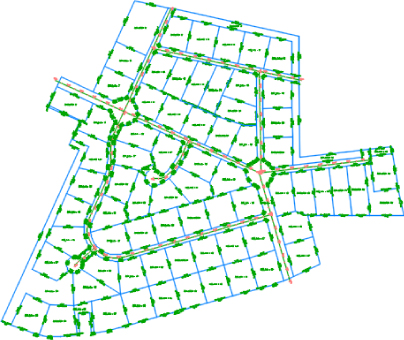
Figure 5.58 A fully labeled site plan
Labeling Multiple-Parcel Segments
The following exercise will teach you how to add labels to multiple-parcel segments:
- Open the
0509_SegmentLabels.dwg(0509_SegmentLabels_METRIC.dwg) file, which you can download from this book's web page.Note that this drawing contains many subdivision lot parcels.
- On the Annotate tab Labels & Tables panel, click the Add Labels icon.
- From the drop-down menus in the Add Labels dialog, select Parcel, Multiple Segment, Bearing Over Distance (from the Parcel Line Label Style section ),and Delta Over Length And Radius in the Feature, Label Type, Line Label Style, and Curve Label Style selection boxes, respectively, as shown in Figure 5.59.
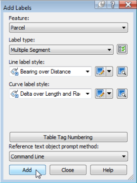
Figure 5.59 The Add Labels dialog
- Click Add.
- At the
Select parcel to be labeled by clicking on area label:prompt, pick the area label for Property : 100. - At the
Label direction [CLockwise/COunterclockwise]<CLockwise>:prompt, press ↵ to accept the default and again to exit the command.Each parcel segment for Property : 100 should now be labeled.
- Continue picking Property : 101 through 105 in the same manner.
Note that segments are never given a duplicate label, even along shared lot lines.
- Press ↵ to exit the command. Close the Add Labels dialog.
- Save the drawing but keep it open for the next exercise. If you would like to see what the drawing should look like at this point, you can open
0509_SegmentLabels_FINISHED.dwg(0509_SegmentLabels_METRIC_FINISHED.dwg), available from the book's website.
The following exercise will show you how to edit and delete parcel segment labels:
- Continue working in the
0509_SegmentLabels.dwg(0509_SegmentLabels_METRIC.dwg) file, or you can open0509_SegmentLabels_FINISHED.dwg(0509_SegmentLabels_METRIC_FINISHED.dwg), available from the book's website. - Zoom in on the label along the frontage of Property : 102.
- Select the segment label.
You'll know your label has been picked when you see a diamond-shaped grip at the label midpoint (see Figure 5.60).
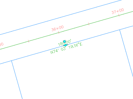
Figure 5.60 A diamond-shaped grip appears when the label has been picked.
- On the Labels – Parcel Segment Label contextual tab Modify panel, click Flip Label, as shown in Figure 5.61.
Figure 5.61 The Parcel Segment Label contextual tab
The label flips so that the bearing component is outside the parcel and the distance component is inside.
- On the Labels – Parcel Segment Label contextual tab Modify panel, click Reverse Label. Press Esc to clear your selection.
The label reverses so that the bearing now reads SW instead of NE.
- Repeat steps 3 through 5 for several other segment labels, and note their reactions.
- Select one of the labels along the back lot lines of parcels 100–105. Once the label is picked, execute the AutoCAD Erase tool or press the Delete key. You will notice that the label disappears, since even though it is dynamically linked to the segment object, it acts independently as an annotation object that can be managed in the same way as other Civil 3D objects.
- Save and close the drawing. If you would like to see what the drawing should look like at this point, you can open
0509_EditSegmentLabels_FINISHED.dwg(0509_EditSegmentLabels_METRIC_FINISHED.dwg), available from the book's website.
Labeling Spanning Segments
Spanning labels are used where you need a label that spans the overall length of an outside segment, such as the example in Figure 5.62.
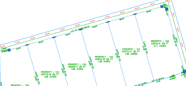
Figure 5.62 A spanning label
Spanning labels require that you use the appropriate vertices, as discussed in detail in the earlier section “Constructing Parcel Segments with the Appropriate Vertices.” Spanning labels have the following requirements:
- Spanning labels can only span split-created vertices. Natural vertices will interrupt a spanning length.
- Spanning label styles must be composed to span the outside segment.
- Spanning label styles must be composed to attach the desired spanning components (such as length and direction arrow) on the outside segment (as shown previously in Figure 5.62), with perhaps a small offset.
Once you've confirmed that your geometry is sound and your label is properly composed, you're set to span. The following exercise will teach you how to add spanning labels to single-parcel segments:
- Open
0510_SpanningLabels.dwg (0510_SpanningLabels_METRIC.dwg), available from the book's website. - Zoom in on the inner parcel segment that runs from Parcel 100 through Parcel 105.
- Change to the Annotate tab and select Add Labels Parcel Add Parcel Labels from the Labels & Tables panel.
- From the drop-down menus in the Add Labels dialog, select Single Segment, (Span) Bearing And Distance With Crows Feet, and Delta Over Length And Radius in the Label Type, Line Label Style, and Curve Label Style selection boxes, respectively.
- Click Add.
- At the
Select point on entity:prompt, pick somewhere near the middle of the outer parcel segment that runs from Parcel 100 through Parcel 105.A label that spans the full length between natural vertices appears (see Figure 5.62).
- As time permits, create other span labels along the other inner lot lines in the project.
- Save and close the drawing. If you would like to see what the drawing should look like at this point, you can open
0510_SpanningLabels_FINISHED.dwg(0510_SpanningLabels_METRIC_FINISHED.dwg), available from the book's website.
Adding Curve Tags to Prepare for Table Creation
To keep plans tidy, it is common to show labels that reference a table for curves and lines. Civil 3D parcels provide tools for creating dynamic line and curve tables. You can keep lines and curves together or create separate tables for each.
Parcel segments must be labeled before they can be used to create a table. They can be labeled with any type of label, but you'll likely find it to be best practice to create a tag-only style for segments that will be placed in a table.
The following exercise will show you how to replace curve and line labels with tag-only labels:
- Open
0511_TagLabels.dwg(0511_TagLabels_METRIC.dwg), available from the book's website.Note that usually the labels along tight curves, such as the cul-de-sac, would be better represented as curve tags.
- Change to the Annotate tab and select Add Labels Parcel Add Parcel Labels from the Labels & Tables panel.
- From the drop-down menus in the Add Labels dialog, select Replace Multiple Segment and for Line Label Style use Line Tag Only, while for the Curve Label Style use Curve Tag Only.
- Click Add. At the
Select parcel to be labeled by clicking on area label:prompt, pick the area label for Parcel 5.Note that the line and curve labels for Parcel 5 are replaced by tag labels.
- Repeat step 4 for Parcels 107 through 114.
- Press ↵ to exit the command.
- Save the drawing but keep it open for the next exercise. If you would like to see what the drawing should look like at this point, you can open
0511_TagLabels_FINISHED.dwg(0511_TagLabels_METRIC_FINISHED.dwg), available from the book's website.
Now that each curve and line label has been replaced with a tag, it's desirable to have the tag numbers be sequential. The following exercise will show you how to renumber tags:
- Continue working in the previous drawing or you can open
0511_TagLabels_FINISHED.dwg(0511_TagLabels_METRIC_FINISHED.dwg), available from the book's website. - Zoom to the curve on the northwest corner of Parcel 5 (see Figure 5.63).
Figure 5.63 Curve tags on Parcel 5 and the northwest corner curve
Your curve may have a different number than the one in the figure.
 Click one of the parcel area labels. Then from the Parcel contextual tab Labels & Tables panel, select Renumber Tags.
- At the
Select label to renumber tag or [Settings]:prompt, typeS, and then press ↵.The Table Tag Numbering dialog appears (see Figure 5.64).
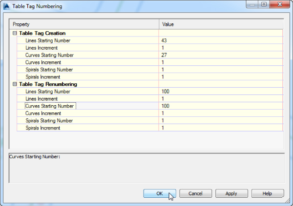
Figure 5.64 The Table Tag Numbering dialog
- Within the Table Tag Renumbering branch, change the value in the Line Starting Number and Curves Starting Number selection boxes to 100, and click OK.
- At the
Select label to renumber tag or [Settings]:prompt, click the curve tag label at the northwest corner of Parcel 5.The command line may say
Current tag number is being used, press return to skip to next available or [Create duplicate], in which case you should typeC↵ to create a duplicate. - Continue clicking curve tag labels working east and then south. As you do so you'll eventually resolve all of the duplicates and end up with a sequential set of curve tag numbers increasing as you move east and then south along the lot frontages. When you're finished, press ↵ to exit the command.
- Save and close the drawing. If you would like to see what the drawing should look like at this point, you can open
0511_TagLabelsRenumbered_FINISHED.dwg(0511_TagLabelsRenumbered_METRIC_FINISHED.dwg), available from the book's website.
Creating a Table for Parcel Segments
The following exercise demonstrates how to create a table from line and curve tags:
- Open
0512_SegmentTable.dwg(0512_SegmentTable_METRIC.dwg), available from the book's website.  Select a parcel area label. From the Parcel contextual tab Labels & Tables panel, select Add Tables Add Segments.
- In the Table Creation dialog, use the one and only option from the drop-down menu in the Table Style selection box.
- In the Select By Label Or Style area of the dialog, click the Apply check box for the Parcel Curve: Curve Tag Only and Line Tag Only entry under Label Style Name. You might have to make the style name column wider to make it easier to pick up the name for the above mentioned styles.
- For both label styles change the Selection Rule to Add Existing And New.
- The Add Existing And New option will ensure that the table updates as more labels fitting this criteria are added to the drawing. Keep the default values for the remaining options. The dialog should look like Figure 5.65.
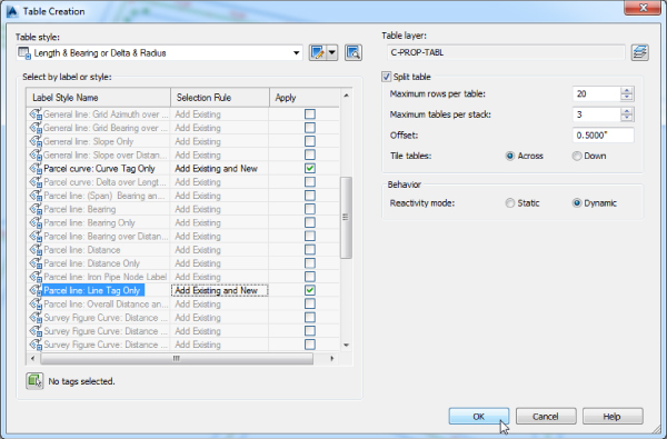
Figure 5.65 The Table Creation dialog
- Click OK.
- At the
Select upper left corner:prompt, pick a location in your drawing for the table. - A segment table appears, shown in Figure 5.66. You will notice that the elements are not sorted in the table. You can enable sorting within the Data Properties tab of the Table Style dialog, which you can access by selecting the table, right-clicking, and choosing the Edit Table Style option from the context menu.
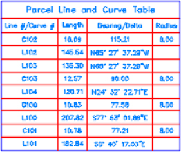
Figure 5.66 A segment table
- Save and close the drawing. If you would like to see what the drawing should look like at this point, you can open
0512_SegmentTable_FINISHED.dwg(0512_SegmentTable_METRIC_FINISHED.dwg), available from the book's website.
The Bottom Line
- Create parcels from objects. The first step in any parceling project is to create an outer boundary for the site together with all the known linework.
- Master It Open the
Masterit_0501.dwg(Masterit_0501_METRIC.dwg) file, which you can download from www.sybex.com/go/masteringcivil3d2015. Convert the polyline segments to parcels and place them in the Subdivision Lots site.
- Master It Open the
- Create a right-of-way parcel using the right-of-way tool. For many projects, the ROW parcel serves as frontage for subdivision parcels. For straightforward sites, the automatic Create ROW tool provides a quick way to create this parcel.
- Master It Continue working in the
Masterit_0501.dwg(Masterit_0501_METRIC.dwg) file or you can openMasterit_0501_FINISHED.dwg(Masterit_0501_METRIC_FINISHED.dwg), available from the book's website. Create a ROW parcel that is offset by 30′ (10 m) on either side of the road centerline with no fillets at boundary ends. Then clean up the ROW parcel area on each side of the alignment at the ends. Note: The south side parcel represents the existing main road ROW.
- Master It Continue working in the
- Create subdivision lots automatically by layout. The biggest challenge when creating a subdivision plan is optimizing the number of lots. The precise sizing parcel tools provide a means to automate this process.
- Master It Continue working in the previous drawing or open
Masterit_0502_FINISHED.dwg(Masterit_0502_METRIC_FINISHED.dwg), available from the book's website. Create a series of lots with a minimum of 10,890 sq. ft. (1,012 m2) and 90′ (30 m) frontage on each side of the ROW beginning at existing ROW and ending at the ROW intersection with the southeast segments of the two north parcels. Set the Use Minimum Frontage At Offset option to No, and redistribute the remainder and set the Minimum Depth and Width values to 50′ (15 m). Leave all other options at their defaults.
- Master It Continue working in the previous drawing or open
- Add multiple-parcel segment labels. Every subdivision plat must be appropriately labeled. You can quickly label parcels with their bearings, distances, direction, and more using the segment labeling tools.
- Master It Continue working in the previous drawing, or you can open
Masterit_0503_FINISHED.dwg(Masterit_0503_METRIC_FINISHED.dwg), available from the book's website. Place Bearing Over Distance labels on every parcel line segment and Delta Over Length And Radius labels on every parcel curve segment using the Multiple Segment Labeling tool.
- Master It Continue working in the previous drawing, or you can open