Chapter 8
Assemblies and Subassemblies
Roads, ditches, trenches, and berms usually follow a predictable pattern known as a typical section. Assemblies are how you tell the Autodesk® AutoCAD® Civil 3D® software what these typical sections look like. Assemblies are made up of smaller components called subassemblies. For example, a typical road section assembly contains subassemblies such as lanes, sidewalks, and curbs.
In this chapter, the focus will be on understanding where these assemblies come from and how to build and manage them.
In this chapter, you will learn to
- Create a typical road assembly with lanes, curbs, gutters, and sidewalks
- Edit an assembly
- Add daylighting to a typical road assembly
Subassemblies
A subassembly is a building block of a typical section, known as an assembly. Examples of subassemblies include lanes, curbs, sidewalks, channels, trenches, daylighting, and any other component required to complete a typical corridor section.
An extensive selection of subassemblies has been created for use in Civil 3D. More than a hundred subassemblies are available in the tool palettes, and each subassembly has a list of adjustable parameters. There are also about a dozen generic links you can use to further refine your most complex assembly needs. From ponds and berms to swales and roads, the design possibilities are almost infinite.
To expand the possibilities even more, you can use the Subassembly Composer to create custom subassemblies from scratch. Subassembly Composer is a separate program whose sole purpose is to build custom subassemblies. You can learn more about Subassembly Composer in the bonus chapter named “Custom Subassemblies” that is available on the book's website, www.sybex.com/go/masteringcivil3d2015.
The Tool Palettes
You will add subassemblies to a design by clicking them from the subassembly tool palette, as you'll see later in this chapter. By default, Civil 3D has several tool palettes created for corridor modeling.
 You can access these tool palettes from the Home tab by clicking the Tool Palettes button on the Palettes panel or by pressing Ctrl+3.
When Civil 3D is installed, you have an initial set of the most commonly used assemblies and subassemblies ready to go. The Tool Palettes window consists of multiple customizable tabs that categorize the assemblies and subassemblies so that they are easy to find.
The top, default tab in the Tool Palettes window is the Assemblies tab. On this tab you will find a selection of predefined, completed assemblies (Figure 8.1). These are a great starting point for beginners who are looking for examples of how subassemblies are put together into an assembly. There are examples of simple roadway sections as well as more advanced items, such as intersections and roundabouts. To use one, click the desired assembly tool on the Tool Palettes window, and then click within the drawing area and press ↵ to end the command.
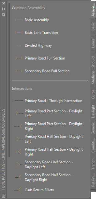
Figure 8.1 Tool Palettes predefined assemblies
The Corridor Modeling Catalogs
All of the assemblies and subassemblies that ship with Civil 3D are included in the Tool Palettes window. However, if any mysteriously disappear, they can be reloaded from the Content Browser.
 The Corridor Modeling Catalogs are installed by default on your local hard drive in
 C:\ProgramData\Autodesk\C3D 2015\enu\Tool Catalogs\Road Catalog\AutoCAD Civil 3D Imperial Corridor Catalog.atc or AutoCAD Civil 3D Metric Corridor Catalog.atc for metric users. You access it on the Home tab by expanding the Palettes panel and clicking the Content Browser button to open the Content Browser interface.
Choose either the metric or Imperial corridor catalogs to explore the entire collection of subassemblies available in each category (see Figure 8.2).
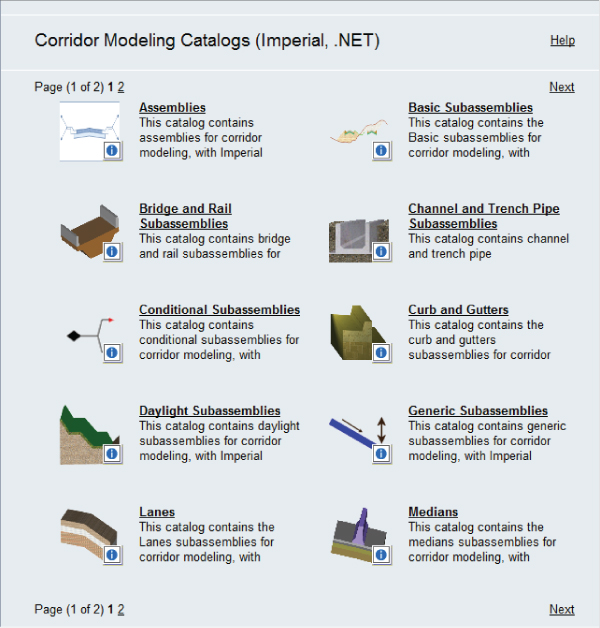
Figure 8.2 The front page of the Corridor Modeling Catalog
Adding Subassemblies to a Tool Palette
 To add subassemblies to your Tool Palettes window, you can use the i-drop to grab subassemblies from the catalog and drop them onto the Tool Palettes window. To use the i-drop, follow these steps:
- Click the small blue i next to any subassembly, and continue to hold down your left mouse button until you're over the desired tool palette.
- Release the button, and your subassembly should appear on the tool palette (see Figure 8.3).
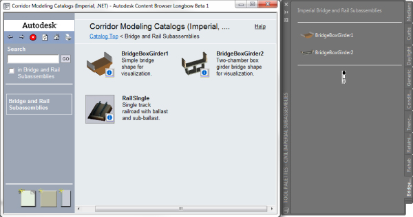
Figure 8.3 Using the i-drop to add the RailSingle subassembly to a tool palette
Building Assemblies
You build an assembly from the Home tab ![]() Create Design panel by choosing Assembly
Create Design panel by choosing Assembly ![]() Create Assembly and selecting an insertion point in the graphic. The result is the main assembly baseline marker. This is the point on the assembly that gets attached to your design alignment and profile. A typical assembly baseline is shown in Figure 8.4.
Create Assembly and selecting an insertion point in the graphic. The result is the main assembly baseline marker. This is the point on the assembly that gets attached to your design alignment and profile. A typical assembly baseline is shown in Figure 8.4.
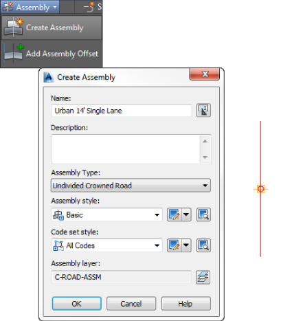
Figure 8.4 Creating an assembly (left); an assembly baseline marker (right)
When an assembly is created, you have the option of telling Civil 3D what type of assembly this will be:
- Undivided Crowned Road
- Undivided Planar Road
- Divided Crowned Road
- Divided Planar Road
- Railway
- Other
These categories will help the software determine the axis of rotation options in superelevation, if needed.
Once an assembly is created and assigned a type, you start piecing it together using various subassemblies to meet your design intent. In the next section we will look at how you can create a simple and very common assembly type, an undivided crowned road.
Creating a Typical Road Assembly
The process for building an assembly requires the use of the Tool Palettes window (accessible using Ctrl+3) and the AutoCAD Properties palette (accessible using Ctrl+1), both of which can be docked. You'll quickly learn how to best orient these palettes with your limited screen real estate. If you run dual monitors, you may find it useful to place both of these palettes on your second monitor.
The exercise that follows builds a typical assembly, as shown in Figure 8.5, using LaneSuperelevationAOR, UrbanCurbGutterGeneral, UrbanSidewalk, and DaylightMaxOffset subassemblies.
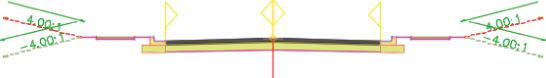
Figure 8.5 A typical road assembly
Let's have a more detailed look at each component you'll use in the following exercise. A quick peek into the subassembly help file will give you a breakdown of attachment options; input parameters; target parameters; output parameters; behavior; layout mode operation; and the point, link, and shape codes.
- The LaneSuperelevationAOR Subassembly The LaneSuperelevationAOR subassembly is an all-purpose subassembly for lanes. It can superelevate for an inside or outside lane if needed and allows for up to four layers of materials. The input parameters available are Side, Width, Default Slope, Pave1 Depth, Pave2 Depth, Base Depth, Subbase Depth, Use Superelevation, Slope Direction, Potential Pivot, Inside Point Code, and Outside Point Code. The default width of 12′ (3.6 m) can be adjusted in the Parameters section of the Properties palette or can be overridden with an offset alignment, feature line, or polyline to control its width. Figure 8.6 shows the image provided in the subassembly help file for this subassembly.
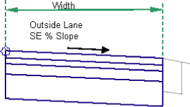
Figure 8.6 LaneSuperelevationAOR subassembly help diagram
- The UrbanCurbGutterGeneral Subassembly The UrbanCurbGutterGeneral subassembly is another standard component that creates an attached curb and gutter. Looking into the subassembly help file, you'll see a diagram of UrbanCurbGutterGeneral with input parameters for Side, Insertion Point, Gutter Slope Method, Gutter Slope, Gutter Slope Direction, Subbase Depth, Subbase Extension, Subbase Slope Method, Subbase Slope, and the subassembly's seven dimensions. You can adjust these parameters to match many standard curb-and-gutter configurations. Figure 8.7 shows the image provided in the subassembly help file for this subassembly.
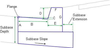
Figure 8.7 UrbanCurbGutterGeneral subassembly help diagram
- The UrbanSidewalk Subassembly The UrbanSidewalk subassembly creates a sidewalk and terrace buffer strips. The help file lists the following six input parameters for the UrbanSidewalk subassembly: Side, Inside Boulevard Width, Sidewalk Width, Outside Boulevard Width, Slope, and Depth. These input parameters let you adjust the sidewalk width, material depth, and buffer widths to match your design specification. Figure 8.8 shows the image provided in the subassembly help file for this subassembly.
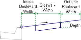
Figure 8.8 UrbanSidewalk : subassembly help diagram
The UrbanSidewalk subassembly can return quantities of concrete (or other sidewalk construction material) but not gravel bedding or other advanced material layers. If you needed to track these materials, you could use generic subassemblies (covered later in this chapter) or build a custom subassembly using Subassembly Composer (covered in the bonus chapter, “Custom Subassemblies”).
- The DaylightMaxOffset Subassembly The DaylightMaxOffset subassembly is a nice “starter” for creating simple, single-slope daylight instructions for your corridor. In Civil 3D, an offset dimension is measured from the baseline, and a width is measured from the attachment point. Therefore, the maximum offset in our example is measured from the centerline of the road, which is the baseline. The slope will attempt a default of 4:1, but it will adjust if it needs to in order to keep inside your specified maximum offset (such as a right-of-way line). Options are also available for rounding. Figure 8.9 shows the image provided in the subassembly help file for this subassembly.
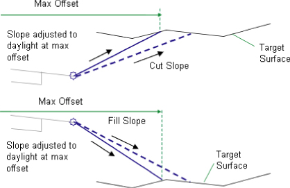
Figure 8.9 DaylightMaxOffset : subassembly help : diagram for the cut scenario
In the following exercise, you'll build a typical road assembly using the subassemblies discussed previously. Follow these steps:
- Start a new blank drawing from the
_AutoCAD Civil 3D (Imperial) NCStemplate that ships with Civil 3D. Metric users can use the_AutoCAD Civil 3D (Metric) NCStemplate. - Confirm that your Tool Palettes window is showing the subassembly set appropriate for your drawing units (imperial or metric).
If you need to change your active Tool Palettes window from metric to Imperial or vice versa, right-click the Tool Palettes control bar located at the top of the window if docked (Figure 8.10a) or on the opposite edge of the palette from the tabs if undocked (Figure 8.10b).
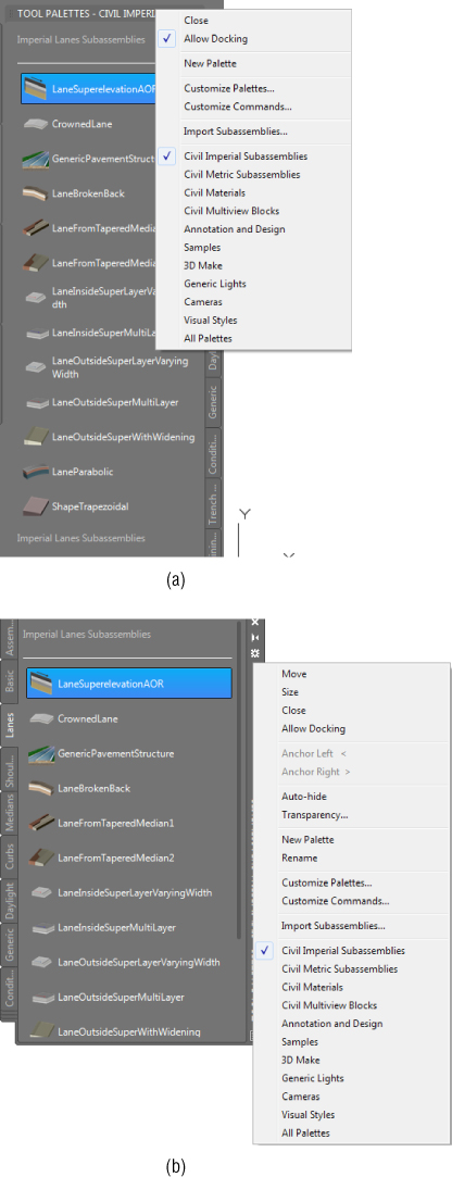
Figure 8.10 Right-click the Tool Palettes control bar to change assembly sets if needed.
- Verify that your drawing scale is set to 1=10′ (1:50 for metric users).
- From the Home tab
 Create Design panel, choose Assembly Create Assembly.
The Create Assembly dialog opens.
- In the Create Assembly dialog, follow these steps:
- Enter Urban 14’ Single-Lane (or Urban 4.5 m Single-Lane) in the Name text box.
- Set Assembly Type to Undivided Crowned Road.
- Confirm that Assembly Style is set to Basic and Code Set Style is set to All Codes, and click OK.
- Pick a location in your drawing to place your red assembly baseline marker. The program will automatically zoom you into the assembly.
- Locate and select the Lanes tab on the Tool Palettes window.
Position the palette on your screen so that you can clearly see the assembly baseline.
- Click the LaneSuperelevationAOR button on the Tool Palettes window.
The AutoCAD Properties palette appears (if it is not already open).
- Locate the Advanced Parameters section on the Design tab of the AutoCAD Properties palette (Figure 8.11).
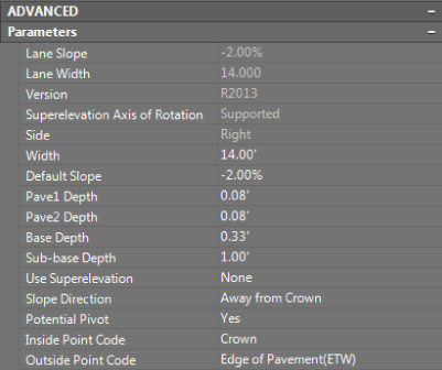
Figure 8.11 Advanced Parameters on the Properties palette
This section lists the LaneSuperelevationAOR parameters.
- Change the Width parameter to 14′ (4.5 m).
Your Properties palette should resemble Figure 8.11.
- At the
Select marker point within assembly or [Insert Replace Detached]:prompt, select anywhere on the red assembly baseline marker to place the first lane.Note that it is placed on the right side as specified in the Advanced Parameters section.
- Before ending the command, click the red assembly baseline marker again to place the left lane.
For most subassemblies, Civil 3D has the intelligence to automatically detect the side and place a subassembly on the appropriate side regardless of what is specified in the Advanced Parameters.
- Press ↵ to end the command.
- Switch to the Curbs tab in the Tool Palettes window.
- Click the UrbanCurbGutterGeneral button on the Tool Palettes window.
- You will accept the parameter defaults, so no changes are needed. Remember that the Side parameter will automatically be detected, so there is no need to change it.
- At the
Select marker point within assembly or [Insert Replace Detached]:prompt, select the circular marker located at the top right of the LaneSuperelevationAOR subassembly located on the right side of the assembly.This marker represents the top-right edge of pavement (see Figure 8.12).
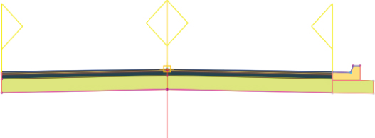
Figure 8.12 UrbanCurbGutterGeneral subassembly placed on the LaneSuperelevationAOR subassembly
- Press ↵ to end the command.
You will add the left curb later. Keep this drawing open for the next portion of the exercise.
- In the Curbs tab, click the UrbanSidewalk button on the Tool Palettes window.
- In the Advanced Parameters area of the AutoCAD Properties palette, change the following parameters, leaving all other parameters at their default values:
- Sidewalk Width: 5′ (1.5 m)
- Inside Boulevard Width: 2′ (0.7 m)
- Outside Boulevard Width: 2′ (0.7 m)
It may be hard to ignore the Side parameter, but setting it is not required with Civil 3D side autodetection.
- At the
Select marker point within assembly or [Insert Replace Detached]:prompt, select the circular marker on the UrbanCurbGutterGeneral subassembly that represents the top rear of the curb to attach the UrbanSidewalk subassembly (see Figure 8.13).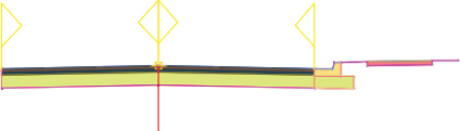
Figure 8.13 BasicSidewalk : subassembly placed on the UrbanCurbGutterGeneral subassembly
- Switch to the Daylight tab on the subassemblies Tool Palettes window, and select the DaylightMaxOffset subassembly.
- In the Advanced Parameters area of the AutoCAD Properties palette, change Max Offset From Baseline to 50′ (17 m), leaving all other parameters at their default values.
- At the
Select marker point within assembly or [Insert Replace Detached]:prompt, select the circular marker on the outermost point of the sidewalk subassembly. Press Enter or Esc to complete the command.Your drawing should now resemble Figure 8.14.
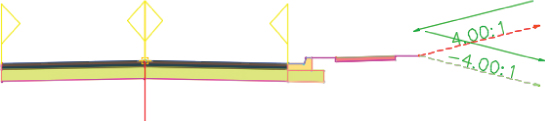
Figure 8.14 The completed right side of the assembly with DaylightMaxOffset
To complete the left side, you will use the Mirror Subassemblies command.
- Select the curb, sidewalk, and daylight subassemblies on the right side of the baseline.
The Subassembly contextual tab will show a variety of tools, including Mirror (Figure 8.15).
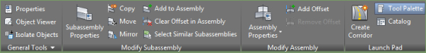
Figure 8.15 The Subassembly contextual tab with subassembly modification tools
- From the Subassembly contextual tab Modify Subassembly panel, choose Mirror, and then click the circular point marker located at the top left of the left LaneSuperelevationAOR subassembly.
- Your assembly should now resemble Figure 8.5 from earlier in the chapter.
You have now completed a typical road assembly.
A finished copy of this drawing is available from the book's web page (0801_TypicalRoadAssembly_FINISHED.dwg or 0801_TypicalRoadAssembly_METRIC_FINISHED.dwg).
Subassembly Components
A subassembly is made up of three basic parts: links, marker points, and shapes, as shown in Figure 8.16. Each piece plays a role in your design and is used for different purposes at each stage of the design process.
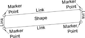
Figure 8.16 Schematic showing parts of a subassembly
Links
Links are the linear components to your assembly. A link usually represents the outer edges of a subassembly but can also be used as a spacer between subassemblies.
Links can have codes assigned to them that help Civil 3D identify stratum, materials, and shapes. One link may have several codes assigned to it. For example, the sidewalk subassembly contains a four-sided trapezoid. Each side of the trapezoid is a link. All four links have a sidewalk code assigned so that cross-sectional area of the concrete can be calculated. The bottom, left, and right links of the trapezoid each have an additional datum code assigned, while the top link has an additional top code assigned. Top and datum codes are used to build surfaces. Coded links will be your primary source of data when creating proposed surfaces from your corridors.
As shown in Figure 8.17, the inner and outer boulevard width links are coded top, sod, and datum.
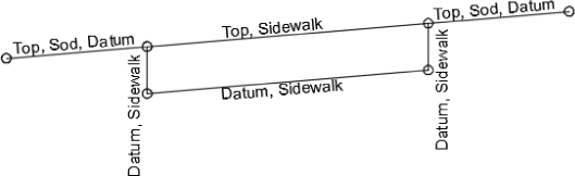
Figure 8.17 Link codes on the UrbanSidewalk subassembly
Marker Points
Marker points are located at the endpoints of every link and usually are depicted by the circles you see on the subassemblies. As you experienced in the previous exercise, the markers are used in assembly creation to “click” subassemblies together and will also “hook” to attach to alignments and/or profiles, known as targets.
Marker points are also coded and responsible for generating linework in your corridor. In Figure 8.18, notice the two coded markers representing each side of the sidewalk. When assemblies are inserted into a corridor, Civil 3D will play connect the dots with each code in between each occurrence of the assembly. In the case of the UrbanSidewalk, linework will be created by connecting the Sidewalk_In point codes and the Sidewalk_Out point codes. We will revisit how a corridor is built in Chapter 9, “Basic Corridors.”
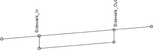
Figure 8.18 Point codes on the UrbanSidewalk
Shapes
Shapes are the areas inside a closed formation of links. For example, Figure 8.19 shows the UrbanSidewalk, which contains one shape. Shapes are used in end-area material quantity calculations. At the time an assembly is created, you do not need to consider what materials these shapes represent. After your corridor is complete, you can specify what materials the codes represent upon computing materials.
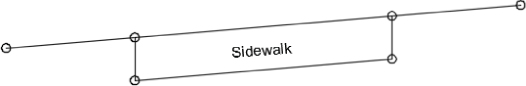
Figure 8.19 Shape codes on the UrbanSidewalk subassembly
Jumping into Help
Each subassembly is capable of accomplishing different tasks in your design. There is no way to tell just by looking at the icon all the acrobatics that an assembly can do. For a detailed rundown of each parameter and what can be done with a subassembly, you will need to pop into the help files.
Subassembly Help is extremely…well, helpful! There are many doors into the help files, including from the Corridor Modeling Catalog as you saw earlier. Another way to access the help files is to right-click any subassembly in the tool palette and select Help, as shown in Figure 8.20.
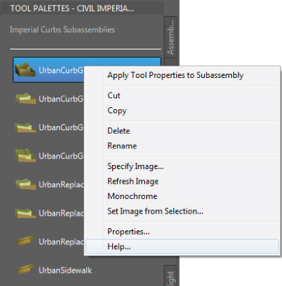
Figure 8.20 Getting to the subassembly help file for UrbanCurbGutterGeneral
Attachment and Input Parameters
When you access Subassembly Help using one of the methods described in the sidebar “Accessing Subassembly Help,” it will take you to the help file specific to the subassembly you are working with. At the top, you will see a diagram showing the location of the numeric parameters that can be edited in the Properties palette, as shown in Figure 8.21.
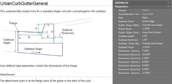
Figure 8.21 The top portion of Subassembly Help shown with subassembly parameters
For most subassemblies, the default attachment point will be the topmost-inside marker point. The help file will tell you if this differs for the subassembly you are looking at. Scroll farther down to see detailed explanations of each input parameter.
Target Parameters
The Target Parameters section is a list of what attachments can be set for a subassembly. There are three types of targets: a target surface, a target elevation, and a target offset. The help file will also tell you whether the target is optional or required. We will look at target parameters and setting targets in Chapter 9.
Output Parameters
Output parameters are values calculated when the corridor is built, such as the cross-slope of a lane. In several subassemblies, there is an advanced option called Parameter Reference that can use an output parameter from a previous subassembly in the assembly instead of using the value entered in the subassembly properties. We discuss this concept further in the bonus chapter, “Custom Subassemblies,” available on this book's web page.
Reading a Coding Diagram
The coding diagram gives you a list of all the codes used on the subassembly you are working with. Every coded point, link, and shape are listed here. Not all subassembly components have explicit names, such as L9 shown in Figure 8.22. If the point, shape, or link is not included in the table, it is considered uncoded.
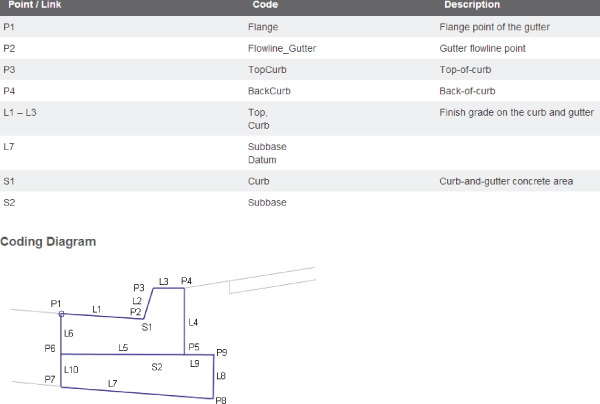
Figure 8.22 Coding diagram and name table for UrbanCurbGutterGeneral
Commonly Used Subassemblies
Once you gain some skills in building assemblies, you can explore the subassembly tool palettes to find subassemblies that have more advanced parameters so that you can get more out of your corridor model. For example, if you must produce detailed schedules of road materials such as asphalt, coarse gravel, fine gravel, subgrade material, and so on, the catalog includes lane subassemblies that allow you to specify those thicknesses for automatic volume reports.
The following sections include some examples of different components you can use in a typical road assembly. Many more alternatives are available within the subassembly tool palettes provided in the software. The help file provides a complete breakdown of each subassembly provided; you'll find this useful as you search for your perfect subassembly.
Each of these subassemblies can be added to an assembly using the same process specified in the first exercise in this chapter. Choose your alternative subassembly instead of the basic parts specified in the exercise, and adjust the parameters accordingly.
Common Lane Subassemblies
The LaneSuperelevationAOR subassembly is suitable for many roads, including undivided roads, as shown in the previous example, and divided roads as shown in Figure 8.23. However, you may need different road lane configurations for your locality or design situation.
- LaneParabolic The LaneParabolic subassembly (Figure 8.24) is used for road sections that require a parabolic lane in contrast to the linear grade of LaneSuperelevationAOR. The LaneParabolic subassembly also adds options for four material depths. This is useful in jurisdictions that require two lifts of asphalt, base material, and sub-base material; taking advantage of these additional parameters gives you an opportunity to build corridor models that can return more detailed quantity takeoffs and volume calculations.
- Note that the LaneParabolic subassembly doesn't have a Side parameter. The parabolic nature of the component results in a single attachment point that would typically be the assembly centerline marker.
- LaneBrokenBack For designs that call for two lanes, and those lanes must each have a unique slope, the LaneBrokenBack subassembly (Figure 8.25) can be used. This subassembly provides parameters to change the road-crown location and specify the width and slope for each lane. Like LaneParabolic, the LaneBrokenBack subassembly provides parameters for additional material thicknesses.

Figure 8.23 LaneSuperelevationAOR in a divided highway
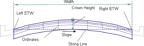
Figure 8.24 The LaneParabolic subassembly help diagram
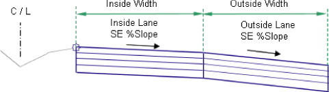
Figure 8.25 The LaneBrokenBack subassembly and parameters
- The LaneBrokenBack subassembly, like LaneSuperelevationAOR, allows for the use of target alignments and profiles to guide the subassembly horizontally and/or vertically for both of the lanes.
Common Shoulder and Curb Subassemblies
There are many types of curbs, and the UrbanCurbGutterGeneral subassembly can't model them all. Sometimes you may need a mountable curb, or perhaps you need a shoulder instead. In those cases, the Curbs tool palette provides many alternatives:
- UrbanCurbGutterValley (1, 2, or 3) The UrbanCurbGutterValley subassemblies are great if you need mountable curbs. UrbanCurbGutterValley 1, 2, and 3, shown in Figure 8.26, Figure 8.27, and Figure 8.28, respectively, vary slightly in how they handle the sub-base slope. UrbanCurbGutterValley 1 also differs because it comes to a point instead of offering a width at the top of curb.
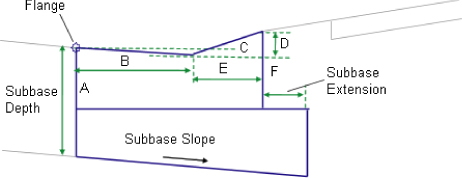
Figure 8.26 UrbanCurbGutterValley1 subassembly help diagram
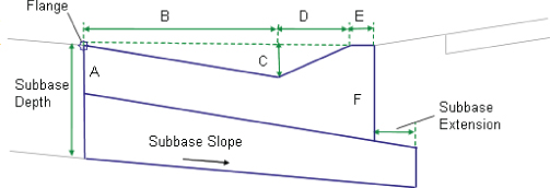
Figure 8.27 UrbanCurbGutterValley2 subassembly help diagram
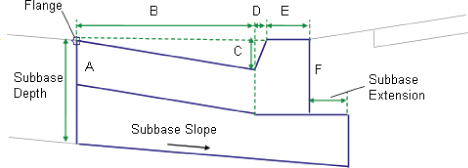
Figure 8.28 UrbanCurbGutterValley3 subassembly help diagram
- BasicShoulder BasicShoulder (see Figure 8.29) is another simple yet effective subassembly for use with road sections that require a shoulder. The predefined shape for this subassembly is called Pave1, which is useful if you are planning to treat this as a paved shoulder and include it in your material quantity calculations.
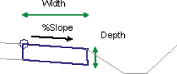
Figure 8.29 BasicShoulder subassembly help diagram
- ShoulderExtendSubbase and ShoulderExtendAll Shoulders that can work with your lanes in a superelevation situation, as these two do, are extremely helpful. These two subassemblies, shown in Figure 8.30, will “play nice” with your breakover-removal settings, as you will see in Chapter 11, “Superelevation.”
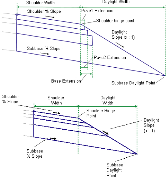
Figure 8.30 ShoulderExtendSubbase subassembly help diagram (top) and ShoulderExtendAll subassembly help diagram (bottom)
Editing an Assembly
As you saw earlier in this chapter, the AutoCAD Properties palette is an option for changing subassembly parameters for one or more subassemblies of the same type. However, there are a handful of settings that can be controlled only in the Civil 3D Subassembly Properties dialog. For example, the side (left or right) is a parameter that must be changed in the Subassembly Properties dialog or on the Construction tab of the Assembly Properties dialog.
Editing a Single Subassembly's Parameters
Once your assembly is created, you can edit individual subassembly components as follows:
- Pick the subassembly component you'd like to edit.
This will bring up the Subassembly contextual tab.
 From the Subassembly contextual tab Modify Subassembly panel, choose the Subassembly Properties option.
The Subassembly Properties dialog appears.
- Switch to the Parameters tab, shown in Figure 8.31, to access the same parameters you saw in the AutoCAD Properties palette when you first placed the subassembly.
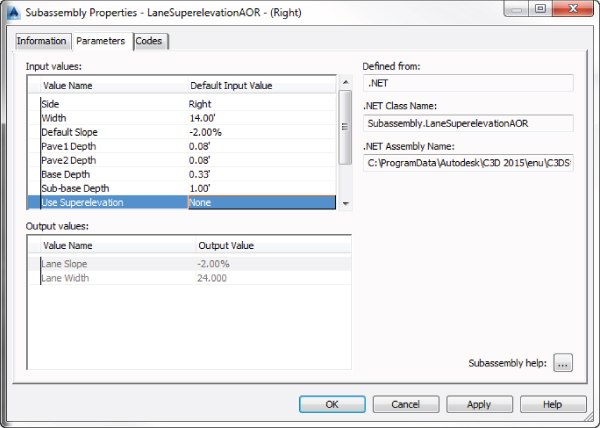
Figure 8.31 Subassembly Properties – Parameters tab
- Click the Subassembly Help ellipsis button at the bottom right of the dialog if you want to access the help page that gives detailed information about the use of this particular subassembly.
Do not confuse the Subassembly Help ellipsis button with the plain Help button, which will just give you help on the Subassembly Properties dialog.
- Close the help file when you've finished viewing it.
- On the Parameters tab of the Subassembly Properties dialog, click inside any field in the Default Input Value column to make changes.
Editing the Entire Assembly
 Sometimes it's more efficient to edit all the subassemblies in an assembly at once. To do so, pick the assembly baseline marker or any subassembly that is connected to the assembly you'd like to edit. This time, select the Assembly Properties option from the Modify Assembly panel of either the Subassembly or Assembly contextual tab to display the Assembly Properties dialog, shown in Figure 8.32.
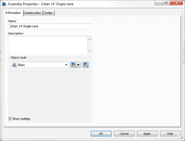
Figure 8.32 Assembly Properties – Information tab
Renaming the Assembly
The Information tab on the Assembly Properties dialog shown in Figure 8.32 gives you an opportunity to rename your assembly and provide an optional description. It is good practice to be consistent and detailed in your assembly names (for example, Divided 4-Lane 12’ w Paved Shoulder). With informative assembly names, you will eliminate much of the guesswork when it comes to building corridors later.
Changing Parameters
The Construction tab in the Assembly Properties dialog, as shown in Figure 8.33, houses each subassembly and its parameters. At the top of the dialog you can change the Assembly Type setting using the drop-down list. In addition, you can change the parameters for individual subassemblies by selecting the subassembly in the Item pane on the left side of the Construction tab and changing the desired parameter in the Input Values pane on the right side.
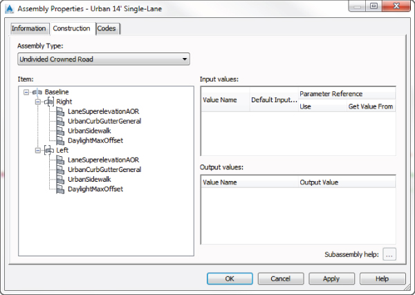
Figure 8.33 Assembly Properties – Construction tab
Renaming Groups and Subassemblies
Note that the left side of the Construction tab displays a list of groups. Under each group is a list of the subassemblies in use in your assembly. A new group is formed every time a subassembly is connected directly to the assembly baseline marker or an offset assembly is added.
With side autodetection, you will notice that the groups have already been named Right and Left with the appropriate symbol next to the group name, as shown in Figure 8.33. The subassemblies in each group appear in the same order in which they were originally placed, usually from the inside out. The first subassembly under the Right group is LaneSuperelevationAOR. If you dig into its parameters on the right side of the dialog, you'll learn that this lane is attached to the right side of the assembly marker, the UrbanCurbGutterGeneral is attached to right side of the LaneSuperelevationAOR, and the UrbanSidewalk is attached to the right side of the UrbanCurbGutterGeneral. In this example, the next group, Left, is identical but attached to the left side of the assembly baseline marker.
If you want, you can rename any of the groups or subassemblies on the Construction tab of the Assembly Properties dialog by right-clicking the group or subassembly you wish to rename and choosing Rename. From this same context menu you can also delete the group or subassembly.
There is no official best practice for renaming your groups and subassemblies, but you may find it useful to keep the designation of what type of subassembly it is or other distinguishing features. For example, if a lane is to be designated as a transition lane or a generic link used as a ditch foreslope, it would be useful to name them descriptively.
Creating Assemblies for Non-road Uses
There are many uses for assemblies and their resulting corridor models aside from road sections. The Corridor Modeling Catalog also includes components for retaining walls, rail sections, bridges, channels, pipe trenches, and much more. In Chapter 9, you'll use a channel assembly and a pipe trench assembly to build corridor models. Let's investigate how those assemblies are put together by building a channel assembly for a stream section:
- Start a new blank drawing from the
_AutoCAD Civil 3D (Imperial) NCStemplate that ships with Civil 3D. Metric users can use the_AutoCAD Civil 3D (Metric) NCStemplate. You can also continue working in your drawing from the first exercise in this chapter. - Confirm that your Tool Palettes window is showing the subassembly set (Imperial or metric) appropriate for your drawing units.
- From the Home tab Create Design panel, choose Assembly Create Assembly.
The Create Assembly dialog opens.
- In the Create Assembly dialog, configure these options:
- Enter Channel in the Name text box.
- Set Assembly Type to Other.
- Confirm that Assembly Style is set to Basic and that Code Set Style is set to All Codes, and click OK.
- Pick a location in your drawing to place your red assembly baseline marker.
- Locate the Trench Pipes tab on the Tool Palettes window.
- Click the Channel subassembly on the Tool Palettes window.
The AutoCAD Properties palette appears.
- Locate the Advanced Parameters area on the AutoCAD Properties palette.
You'll place the channel with its default parameters and make adjustments through the Assembly Properties dialog, so don't change anything for now. Note that there is no Side parameter. This subassembly will be centered on the assembly baseline marker.
- At the
Select marker point within assembly or [Insert Replace Detached]:prompt, select the red assembly baseline marker, and a channel is placed on the assembly (see Figure 8.34).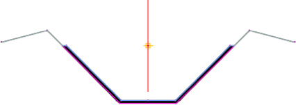
Figure 8.34 The Channel subassembly with default parameters
- Press Esc to leave the assembly insertion command and dismiss the Properties palette.
- Click the assembly baseline marker, and then on the Assemblies contextual tab Modify Assembly palette, click Assembly Properties.
The Assembly Properties dialog appears.
- Switch to the Construction tab.
Notice that while the typical road assembly in the previous exercise generated a Left group and a Right group, the Channel subassembly generated a Centered group.
- Select the Channel entry on the left side of the dialog (under the Centered group).
- Click the Subassembly Help ellipsis button located at the bottom right on the dialog's Construction tab.
The Subassembly Reference page of the AutoCAD Civil 3D 2015 help file appears.
- Familiarize yourself with the diagram, shown in Figure 8.35, and the input parameters for the Channel subassembly.
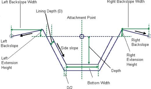
Figure 8.35 The Channel subassembly help diagram
Especially note the Attachment Point, Bottom Width, Depth, and Side slope parameters. The attachment point indicates where your baseline alignment and profile will be applied.
- Minimize or close the help file.
To match the engineer's specified design, you need a stream section 6′ (2 m) deep with a bottom that's 3′ (1 m) wide, 1:1 sideslopes, and no backslopes.
- Change the following parameters in the Assembly Properties dialog, leaving all other parameters at their default values:
- Depth: 6′ (2 m)
- Bottom Width: 3′ (1 m)
- Sideslope: 1 (value will automatically change to be displayed as 1.00:1)
Left and Right Backslope Width: 0′ (0 m)
- Click OK, and confirm that your completed assembly looks like Figure 8.36.
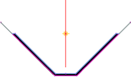
Figure 8.36 The channel assembly with customized parameters
A finished copy of this drawing is available from the book's web page (0802_ChannelAssembly_FINISHED.dwg or 0802_ChannelAssembly_METRIC_FINISHED.dwg).
Specialized Subassemblies
Despite the more than 100 subassemblies available in the Corridor Modeling Catalog, sometimes you may not find the perfect component. Perhaps none of the channel assemblies exactly meet your design specifications and you'd like to make a more customized assembly, or neither of the sidewalk subassemblies allows for the proper boulevard slopes. Maybe you'd like to try to do some preliminary lot grading using your corridor or mark a certain point on your subassembly so that you can extract important features easily.
You can handle most of these situations by using subassemblies from the Generic Subassembly Catalog (see Figure 8.37). These simple yet flexible components can be used to build almost anything, although they lack the coded intelligence of some of the more intricate subassemblies (such as knowing if they're paved or grass and understanding things like sub-base depth and so on).
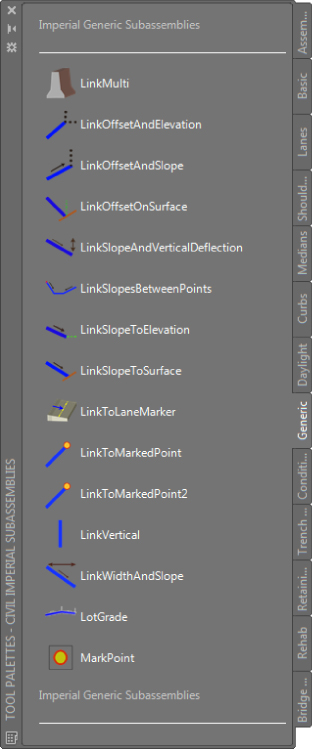
Figure 8.37 The Generic Subassembly tool palette
Using Generic Links
Let's look at two examples where you might take advantage of generic links.
The first example involves the typical road section you built in the first exercise in this chapter. You saw that UrbanSidewalk applies one continuous cross-slope across the inside boulevard (terrace), sidewalk, and outside boulevard (buffer strip). If you need a terrace that's 3′ (1 m) wide with a 3 percent slope, and then a 5′ (1.5 m) sidewalk with a 2 percent slope, followed by another buffer strip that is 6′ (2 m) wide with a slope of 5 percent, you can use generic links to assist in the construction of the proper assembly.
In this exercise you will be creating a new assembly based on the typical road assembly made in the first exercise.
- Open
801_TypicalRoadAssembly_FINISHED.dwgor0801_TypicalRoadAssembly_METRIC_FINISHED.dwg, available on the book's website. - In Prospector, locate and expand the Assemblies group.
- Right-click Urban 14′ Single-Lane or Urban 4.5 m Single-Lane and select Zoom To.
- Select the lane and curb subassemblies as well as the assembly baseline marker and Mtext below; then on the Home tab Clipboard panel, click Copy Clip.
- On the Home tab Clipboard panel, click Paste. Pick a location directly under the Urban Single-Lane assembly to paste the copied assembly. Notice that the Mtext updated to the name of the copy of the assembly. This is because it's a field.
You could have use the copy command. However, when the assembly baseline marker is part of the copy command selection set, the entire assembly is copied even if some of the subassemblies are not included in the selection set. If this were your method in this exercise, all you would need to do next would be to delete the unwanted subassemblies.
While you could place the subassembly anywhere, you will find that as you gather more and more assemblies in a drawing, having them organized in a logical manner with similar assemblies in a common area makes them easier to manage.
- Select the assembly baseline marker; then on the Assembly contextual tab Modify Assembly Panel, click Assembly Properties.
The Assembly Properties dialog appears.
- On the Information tab, change Name to Urban 14’ Single-Lane with Terraced Sidewalk (or Urban 4.5 m Single-Lane With Terraced Sidewalk) and click OK.
If you copied the Mtext label containing a field, you may want to run a
REGENto update the label or play with the grips to stack the text legibly. - Locate the Generic tab on the Tool Palettes window.
- Click the LinkWidthAndSlope subassembly (you may need to scroll down to find it), and the AutoCAD Properties palette appears.
- Scroll down to the Advanced Parameters section of the Properties palette and change the parameters as follows to create the first buffer strip, leaving all other parameters at their default values:
- Width: 3′ (1 m)
- Slope: 3%
- At the
Select marker point within assembly or [Insert Replace Detached]:prompt, select the circular marker on the right UrbanCurbGutterGeneral subassembly as well as the circular marker on the left UrbanCurbGutterGeneral subassembly, both of which represent the top back of the curb. - Switch to the Curbs tab of the Tool Palettes window, and click the UrbanSidewalk button.
- In the Advanced Parameters area of the Properties palette, change the parameters as follows to create the sidewalk, leaving all other parameters at their default values:
- Inside Boulevard Width: 0′ (0 m)
- Sidewalk Width: 5′ (1.5 m)
- Outside Boulevard Width: 0′ (0 m)
- Slope: 2%
- At the
Select marker point within assembly or [Insert Replace Detached]:prompt, select the upper-right circular marker on the right LinkWidthAndSlope subassembly and the upper-left circular marker on the left LinkWidthAndSlope subassembly. - Switch to the Generic tab of the Tool Palettes window, and click the LinkWidthAndSlope button.
The AutoCAD Properties palette appears.
- In the Advanced Parameters area, change the parameters as follows to create the second buffer strip, leaving all other parameters at their default values:
- Width: 6′ (2 m)
- Slope: 5%
- At the
Select marker point within assembly or [Insert Replace Detached]:prompt, select the upper-right circular marker on the right UrbanSidewalk subassembly, as well as the upper-left circular marker on the left UrbanSidewalk subassembly, both of which represent the outside edge of the sidewalk. When complete, press Esc to end the command. - Select the right daylight subassembly from the Urban Single-Lane assembly. On the Subassembly contextual tab Modify Subassembly panel, click Copy.
- Select the outermost marker on the right side of the new assembly that you are working on. Do the same for the left daylight.
The completed assembly should look like Figure 8.38 (shown with the typical road assembly from the first exercise for comparison).
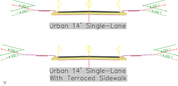
Figure 8.38 The completed Urban Single-Lane assembly from the first exercise (top) and the Urban Single-Lane with Terraced Sidewalks assembly (bottom)
You may keep this drawing open to continue on to the next exercise, or use the finished copy of this drawing available from the book's web page (
0804_GenericLinksAssembly_FINISHED.dwgor0804_GenericLinksAssembly_METRIC_FINISHED.dwg).You've now created a custom sidewalk terrace for a typical road.
Daylighting with Generic Links
The next example involves the channel section you built earlier in this chapter. This exercise will lead you through using the LinkSlopeToSurface generic subassembly, which will provide a surface target to the channel assembly that will seek the target assembly at a 25 percent slope. For more information about surface targets, see Chapter 9.
In this exercise, you will be creating another new assembly based on the channel assembly exercise.
- Open
0802_ChannelAssembly_FINISHED.dwgor0802_ChannelAssembly_METRIC_FINISHED.dwg, available on the book's website. - In Prospector, locate and expand the Assemblies group.
- Right-click Channel and select Zoom To.
- Locate the Generic tab on the Tool Palettes window.
- Click the LinkSlopeToSurface button.
- In the Advanced Parameters area of the Properties palette, change the Slope parameter to 25%, leaving all other parameters at their default values.
- At the
Select marker point within assembly or [Insert Replace Detached]:prompt, select the circular marker at the upper right on the channel subassembly as well as the circular marker on the upper left on the channel subassembly. Press Esc to end the command.The left surface target link appears, but it is sloping to the right instead of the left. This is one subassembly that doesn't automatically “flip” to the appropriate side.
- Select the LinkSlopeToSurface subassembly to activate the Subassembly contextual tab.
- From the Subassembly contextual tab Modify Subassembly panel, choose Subassembly Properties.
- On the Parameters tab, locate the Side input value, and click the default input value field.
- In the Pick Default Value dialog, select Left as the new input value and click OK.
- Click OK to dismiss the Subassembly Properties dialog.
The completed assembly should look like Figure 8.39.
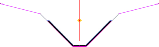
Figure 8.39 The completed channel assembly
You may keep this drawing open to continue on to the next exercise or use the finished copy of this drawing available from the book's web page (0805_ChannelLinkDaylight_FINISHED.dwg or 0805_ChannelLinkDaylight_METRIC_FINISHED.dwg).
Adding a surface link to the channel assembly provides a surface target for the assembly. Now that you've added the LinkSlopeToSurface, you will be able to specify your existing ground as the surface target for a corridor, and the subassembly will grade between the top of the bank and the surface for you. You can achieve additional flexibility for connecting to existing ground with the more complex daylight subassemblies, as discussed in the next section.
Working with Daylight Subassemblies
In previous examples, we worked with a generic daylight subassembly, but now let's take a closer look at what they can do for you.
A daylight subassembly tells Civil 3D how to extend a link to a target surface. The instructions might specify that a ditch or berm be inserted before looking for existing ground. Others provide a straight shot but with contingencies for certain design conditions. Figure 8.40 shows the many options you have for adding a daylight subassembly to an assembly.
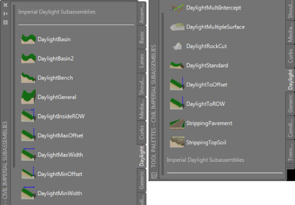
Figure 8.40 Daylight subassemblies in the Tool Palettes window
In the following exercise, you'll use the DaylightInsideROW subassembly. This subassembly contains parameters for specifying the maximum distance from the centerline or offset alignments. If the 4:1 slope hits the surface inside the right-of-way (ROW), no adjustment is made to the slope. If 4:1 causes the daylight to hit outside of the ROW, the slope adjusts to stay inside the specified location.
In this exercise you will be creating a new assembly based on the typical road assembly you made in the first exercise.
- Open
0804_GenericLinksAssembly_FINISHED.dwgor0804_GenericLinksAssembly_METRIC_FINISHED.dwg, available from the book's website. - Locate the Urban 14′ Single-Lane or Urban 4.5 m Single-Lane assembly.
- Select the lane, curb, and sidewalk subassemblies as well as the assembly baseline marker and the Mtext displaying the assembly name. On the Home tab Clipboard panel, click Copy Clip.
- On the Home tab Clipboard panel, click Paste and pick a location directly over the Urban Single-Lane assemblies to paste the copied assembly.
- Click the assembly baseline marker, and then on the Assemblies contextual tab Modify Assembly palette, click Assembly Properties.
The Assembly Properties dialog appears.
- On the Information tab, change the name to Urban 14’ Single-Lane Daylight ROW (or Urban 4.5 m Single-Lane Daylight ROW), and click OK. Run a
REGENto update Mtext. - Locate the Daylight tab on the Tool Palettes window.
- Right-click the DaylightInsideROW button on the Tool Palettes panel and select Help.
The Subassembly Reference page opens in a new window.
- Familiarize yourself with the options for the DaylightInsideROW subassembly, especially noting the optional parameters for a lined material, a mandatory daylight surface target, and an optional ROW offset target that can be used to override the ROW offset specified in the parameters.
- Close the Help dialog. Click the DaylightInsideROW button on the Tool Palettes window.
- In the Advanced Parameters area of the Properties palette, change the parameter ROW Offset From Baseline to 33′ (10 m), leaving all other parameters at their default values.
- At the
Select marker point within assembly or [Insert Replace Detached]:prompt, select the circular marker on the farthest-right link on the new assembly. TheSelect marker point within assembly or [Insert Replace Detached]:prompt is still active. - On the Properties palette, in the Advanced Parameters area, change the parameter ROW Offset From Baseline to -33’ (-10 m) and then place the subassembly on the left side of the new assembly. Press Esc to end the command.
Notice that there is no Left or Right parameter. The negative value in the ROW Offset From Baseline parameter is what tells Civil 3D the daylight is to the left. Some subassemblies will contain an offset parameter instead of a side parameter to direct to which side it should flip. In the case of an offset parameter, left will be indicated by a negative value and right will be indicated by a positive value.
- You can now dismiss the Properties palette.
The completed assembly should look like Figure 8.41.
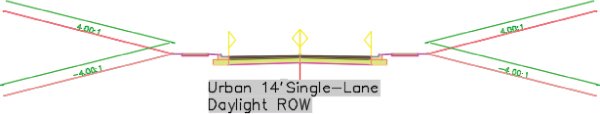
Figure 8.41 An assembly with the DaylightInsideROW subassembly attached to each side
You may keep this drawing open to continue on to the next exercise or use the finished copy of this drawing available from the book's web page (DaylightROWAssembly_FINISHED.dwg or DaylightROWAssembly_METRIC_FINISHED.dwg).
Alternative Daylight Subassemblies
Over a dozen daylight subassemblies are available, varying from a simple cut-fill parameter to a more complicated benching or basin design. Your engineering requirements may dictate something more challenging than the exercise in the previous section. Here are some alternative daylight subassemblies and the situations where you might use them. For more information on any of these subassemblies and the many other daylighting choices, see the AutoCAD Civil 3D 2015 Subassembly Reference page in the help file.
- DaylightToROW and DaylightInsideROW The DaylightToROW subassembly differs slightly from the DaylightInsideROW, as shown in Figure 8.42. DaylightToROW constantly adjusts the slope to stay a certain distance away from your ROW, as specified by the Offset Adjustment input parameter. For example, you can have a ROW alignment specified but use this subassembly to tell Civil 3D to always stay 3′ inside the ROW line. The DaylightInsideROW uses the typical slope but adjusts up to a maximum slope in order to stay inside of the ROW. In both subassemblies, you must specify an offset value or an offset target to use as the ROW.
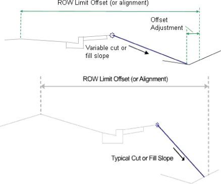
Figure 8.42 DaylightToROW subassembly help diagram (top) and DaylightInsideROW subassembly help diagram (bottom)
- BasicSideSlopeCutDitch In addition to including cut-and-fill parameters, the BasicSideSlopeCutDitch subassembly (see Figure 8.43) creates a ditch in a cut condition. This is most useful for road designs that require a roadside ditch through cut sections but omit it when passing through areas of fill. If your corridor model is revised in a way that changes the location of cut-and-fill boundaries, the ditch will automatically adjust. Note that this subassembly is located on the Basic tab whereas the other subassemblies in this section are located on the Daylight tab.
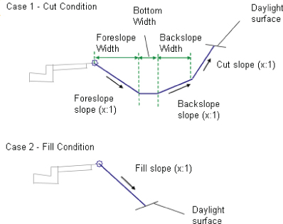
Figure 8.43 BasicSideSlopeCutDitch subassembly help diagram
When you insert this subassembly, you will notice that it does not look anything like the help diagram and instead will display the “Layout Mode” text on the design assembly, as shown in Figure 8.44. This will not display on the completed corridor. There are several subassemblies where this will occur—which is another good reason to always check the help file for an accurate representation of what the final product will look like.
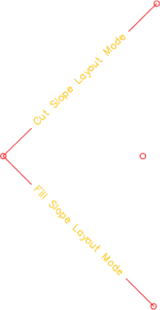
Figure 8.44 BasicSideSlopeCutDitch in layout mode
- DaylightBasin Many engineers must design berms to contain roadside swales when the road design is in the fill condition. The process for determining where these berms are required is often tedious. The DaylightBasin subassembly (see Figure 8.45) provides a tool for automatically creating these “false berms.” The subassembly contains parameters for the specification of a basin (which can be easily adapted to most roadside ditch cross sections as well) and parameters for containment berms that appear only when the subassembly runs into areas of roadside cut.
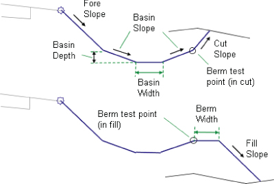
Figure 8.45 The DaylightBasin subassembly help diagram
Advanced Assemblies
As you get to know Civil 3D better, you will want it to do more for you. With the tools you are given and your own creativity and problem-solving skills, you can use Civil 3D to create some complex designs. Offset assemblies and marked point assemblies are powerful tools you have at your fingertips.
Offset Assemblies
Offset assemblies are an advanced option when you want to model a coordinating component of the design whose cross section is related to the main assembly. An example of where an offset assembly would be helpful is a main road adjacent to a meandering bike path. The bike path generally follows the main road, but its alignment is not always parallel and the profile might be altogether different. Figure 8.46 shows what the assembly for a bike path to the left of a road would look like.
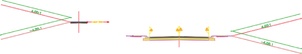
Figure 8.46 An example of an assembly with an offset to the left representing a bike path
To use an offset assembly, from the Home tab ![]() Create Design panel, choose Assembly
Create Design panel, choose Assembly ![]() Add Assembly Offset. You will be prompted to select the main assembly and place the offset in the graphic. The location of the offset assembly in relation to the main assembly will have no effect on the final design.
Add Assembly Offset. You will be prompted to select the main assembly and place the offset in the graphic. The location of the offset assembly in relation to the main assembly will have no effect on the final design.
Once the offset assembly is placed, the construction of the offset assembly is identical to any other assembly. We will use an example of an assembly with an offset in Chapter 10, “Advanced Corridors, Intersections, and Roundabouts.”
Marked Points Used with Partner Subassemblies
The marked point assembly is a small but powerful subassembly found in the Generic palette. It consists of a single marker, and you can place it on an assembly to flag a location. You can use the marked point by itself to generate a feature line where no coded marker currently exists, say in the midpoint of a lane link. Marked points really perform when used with one of the subassemblies designed to tie into a marked point.
When using a marked point, name it right away, and make note of that name for using it with a partner subassembly (Figure 8.47).
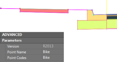
Figure 8.47 Name the marked point in the Advanced Parameters area of the Properties palette
Linking to a Marked Point
In the example shown in Figure 8.48, a LinkToMarkedPoint2 subassembly is placed on the right side of the bike path pavement. The LinkToMarkedPoint2 subassembly has been created to look for the marked point on the left side of the sidewalk buffer.
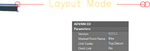
Figure 8.48 Add the name of the marked point before you place it on the assembly.
When placing a marked point, enter a descriptive and unique Point Name value under Advanced Parameters. Remember to enter that same descriptive and unique name into the partner subassembly's corresponding field called Marked Point Name. Upon doing this, you will not see the geometry tie together on the assembly, but it will in the resulting corridor, as you will see in Chapter 10.
All subassemblies that use the marked point will appear with the “Layout Mode” placeholder. The following subassemblies are designed to look for a marked point:
- Channel
- ChannelParabolicBottom
- LinkToMarkedPoint
- LinkToMarkedPoint2
- LinkSlopesBetweenPoints
- MedianDepressed
- MedianRaisedConstantSlope
- MedianRaisedWithCrown
- OverlayBrokenBackBetweenEdges
- OverlayBrokenBackOverGutters
- OverlayCrown
- OverlayParabolic
- UrbanReplaceCurbGutter1
- UrbanReplaceCurbGutter2
- UrbanReplaceSidewalk
Organizing Your Assemblies
The more geometry changes that occur throughout your corridor, the more assemblies you will have. Civil 3D offers several tools to keep your assemblies organized and available for future use.
Storing a Customized Subassembly on a Tool Palette
Customizing subassemblies and creating assemblies are both simple tasks. However, you'll save time in future projects if you store these items for later use.
A typical jurisdiction usually has a finite number of allowable lane widths, curb types, and other components. It would be extremely beneficial to have the right subassemblies with the parameters already available on your Tool Palettes window.
The following exercise will lead you through storing a customized subassembly on a tool palette.
In this exercise you will be storing some of the subassemblies you made in earlier exercises; therefore, any of the previously saved files (which you can download from this book's web page) can be used, if you do not have one open from a previous exercise.
You can add a tool only from a saved drawing, so make sure you save the drawing you are working in before following these steps:
- Be sure your Tool Palettes window is displayed.
- Right-click the Tool Palettes control bar located at the top of the window or side opposite of tabs if undocked, and select New Palette to create a new tool palette.
- Enter My Road Parts in the Name text box.
- Select one of the sidewalk subassemblies from the Urban 14′ Single-Lane assembly.
- You'll know it's selected when you see it highlighted and the grip appears.
Click any link in the assembly (not the grip), and while holding down the left mouse button drag the assembly into the Tool Palettes window. Release the mouse button.
 It may take you several tries to get the click-and-drag timing correct, but it will work. You'll know it is working when the cursor appears with a plus sign in the tool palette.
When you release the mouse button, an entry appears on your tool palette with the name of the subassembly component that you are adding as well as a graphic of the subassembly.
- Select and right-click this entry, and select the Properties option.
The Tool Properties dialog appears (see Figure 8.49).
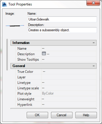
Figure 8.49 The Tool Properties dialog
- If desired, change the image, description, and other parameters in the Tool Properties dialog, and click OK.
- Try this process for other subassemblies in the drawing.
The resulting tool palette could look similar to Figure 8.50.
Figure 8.50 A tool palette with five customized subassemblies
Note that the tool palette entries for each subassembly pull from C3DStockSubassemblies.dll file installed locally. The subassembly will not pull from this drawing as do blocks. If you share this tool palette, there is no need to share the drawing.
Storing a Completed Assembly on a Tool Palette
In addition to storing individual subassemblies on a tool palette, it's often useful to store entire completed assemblies. Many jurisdictions have several standard roadway sections; once each standard assembly has been built, you can save time on future projects by pulling in a stored version of this assembly.
The process for storing an assembly on a tool palette is nearly identical to the process of storing a subassembly. Simply select the assembly baseline, hover your cursor over the assembly baseline, left-click, and drag to a palette of your choosing.
It's usually a good idea to create a library drawing in a shared network location for common completed assemblies and to create all assemblies in that drawing before dragging them onto the tool palette. By using this approach, you'll be able to test your assemblies for validity before they are rolled into production. Alternatively, you can right-click the new palette name and choose Import Subassemblies to display the Import Subassemblies dialog. Here you can choose a source file and then specify whether you want the subassemblies from that source file to import into the palette (optional) and/or the Catalog Library/My Imported Tools.
The Bottom Line
- Create a typical road assembly with lanes, curbs, gutters, and sidewalks. Most corridors are built to model roads. The most common assembly used in these road corridors is some variation of a typical road section consisting of lanes, curbs, gutters, and sidewalks.
- Master It Create a new drawing from either the Civil 3D metric or Imperial template. Build a symmetric assembly using LaneSuperelevationAOR, UrbanCurbGutterValley2, and LinkWidthAndSlope for terrace and buffer strips adjacent to the UrbanSidewalk. Use widths and slopes of your choosing.
- Edit an assembly. Once an assembly has been created, it can be easily edited to reflect a design change. Often, at the beginning of a project you won't know the final lane width. You can build your assembly and corridor model with one lane width and then change the width and rebuild the model immediately.
- Master It Working in the drawing from the preceding exercise, edit the width of each LaneSuperelevationAOR to 14′ (4.3 m), and change the cross slope of each LaneSuperelevationAOR to -3.00%.
- Add daylighting to a typical road assembly. Often, the most difficult part of a designer's job is figuring out how to grade the area between the last engineered structure point in the cross section (such as the back of a sidewalk) and the existing ground. An extensive catalog of daylighting subassemblies can assist you with this task.
- Master It Working in the drawing from the preceding exercise, add the DaylightMinWidth subassembly to both sides of your typical road assembly. Establish a minimum width between the outermost subassembly and the daylight offset of 10′ (3 m).