Chapter 14
Grading
Beyond creating streets, sewers, cul-de-sacs, and inlets, much of what happens to the ground as a site still needs to be determined. Planning for the earthwork of a site is a crucial part of bringing a project together. This chapter examines feature lines and grading groups, which are the two primary tools of site design. Feature lines and grading groups work in tandem, providing the site designer with tools to completely model the land.
In this chapter, you will learn to
- Convert existing linework into feature lines
- Model a simple breakline with a feature line
- Model planar site features with grading groups
Working with Grading Feature Lines
There are two types of feature lines: corridor feature lines and grading feature lines. Corridor feature lines are discussed in Chapter 9, “Basic Corridors,” and grading feature lines are the focus of this chapter. It's important to note that grading feature lines can be extracted from corridor feature lines, and you can choose whether or not to dynamically link them to the corridor.
Terrain modeling can be defined as the manipulation of triangles created by connecting points and vertices to achieve Delaunay triangulation, as discussed in Chapter 4, “Surfaces.” In the Autodesk® AutoCAD® Civil 3D® platform, the creation of the Feature Line object adds a level of control and complexity not available to 3D polylines. In this section, you'll look at the feature line, various methods of creating feature lines, some simple elevation edits, planar grading and editing functionality, and labeling of the newly created feature lines.
Accessing Grading Feature Line Tools
The Feature Line creation tools can be accessed from the Home tab's Create Design panel, as shown in Figure 14.2.
The Feature Line editing tools can be accessed via the Feature Line contextual tab (see Figure 14.1). To activate the Feature Line contextual tab, just select a feature line, or from the Modify tab ![]() Design panel, choose Feature Line.
Design panel, choose Feature Line.
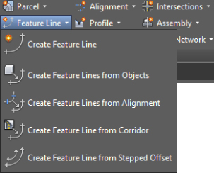
Figure 14.1 The Feature Line contextual tab can be accessed by selecting an existing feature line
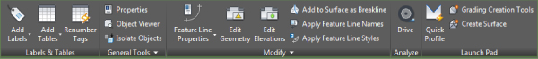
Figure 14.2 The Feature Line drop-down on the Create Design panel
When you're working with feature lines, one thing to remember is that they belong in a site, as shown in Figure 14.3. Feature lines within the same site snap to each other vertically, which can cause some confusion when you're trying to build surfaces.
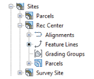
Figure 14.3 Feature lines are located in the Sites branch in Prospector
The next few sections break down the various tools in detail. You'll use almost all of them in this chapter, so in each section you'll spend some time getting familiar with these tools and the basic concepts behind them.
Creating Grading Feature Lines
 There are five primary methods for creating feature lines, as shown previously in Figure 14.2. They generate similar results but have some key differences:
- Create Feature Line The Create Feature Line tool allows you to create a feature line from scratch, assigning elevations as you go. These elevations can be based on direct data input at the command line, slope information, elevation difference, or surface elevations.
- Create Feature Lines From Objects The Create Feature Lines From Objects tool converts lines, arcs, polylines, and 3D polylines into feature lines. This process also allows you to assign elevations. You can assign a single elevation to all vertices on the feature line. You can also acquire elevations from grading groups and surfaces if the feature line has been drawn over either. You also have the option to delete the original object or weed the vertices of the new feature line.
- Create Feature Lines From Alignment The Create Feature Lines From Alignment tool allows you to build a new feature line from an alignment, using a profile to assign elevations. This feature line can be dynamically tied to the alignment and the profile, which limits your ability to edit it directly, but makes it easy to generate feature lines based on horizontal and vertical controls of alignments and profiles. If the feature line created from an alignment is not dynamically linked, any of the feature-line editing commands can be used. This could be useful if you wanted to place a vertical curve in your feature line.
- Create Feature Line From Corridor The Create Feature Line From Corridor tool is used to export a grading feature line from a corridor feature line. The feature line created from a corridor feature line can be dynamically linked to the corridor. If the feature line is dynamically linked, then it can't be edited with the feature line editing tools.
- Create Feature Line From Stepped Offset The Create Feature Line From Stepped Offset tool is used to create an offset feature line, allowing you to specify a vertical offset value in terms of elevation difference, grade, slope, and actual elevation for the entire feature line or each vertex. You can also define variable stepped offsets at each feature line vertex. This tool can also be used on feature lines, survey figures, polylines, or 3D polylines. The feature line created from a stepped offset does not keep a dynamic link to the original feature line.
You'll explore some of these methods over the next few exercises. In this first exercise, you will create the edge of a tennis court with a feature line:
- Open the
1401_CreatingFeatureLines.dwgor1401_CreatingFeatureLines_METRIC.dwgfile. (Remember, all data can be downloaded from www.sybex.com/go/masteringcivil3d2015.)This drawing contains some AutoCAD entities and Civil 3D points representing basic geometry for a recreational center at the entrance of the subdivision.
 From the Home
  Create Design panel, choose Feature Line Create Feature Line to display the Create Feature Lines dialog.
You need to associate feature lines with a site. Just like parcels, grading objects will react with like objects in a site if they touch, horizontally in particular. So by isolating this feature line, you can ensure that everything will be drawn properly before committing it to a site.
- Verify that Rec Center is the Site name.
- Fill in the check box next to Style and select Grading Edge Of Pavement as the style name using the drop-down.
The Create Feature Lines dialog should now look like Figure 14.4.
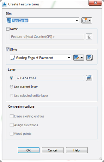
Figure 14.4 The Create Feature Lines dialog
- Click OK to dismiss the Create Feature Lines dialog.
- At the
Specify start point:prompt, use a Node Osnap to specify your start point as point #1. - At the
Specify elevation or [Surface]:prompt, enter S ↵ to use a surface to set the elevation.Since there are multiple surfaces in the drawing, the Select Surface dialog appears. If there were only one surface in this drawing, the surface would automatically be selected and you would not be prompted with this dialog.
- In the Select Surface dialog, use the drop-down to choose Existing Surface and click OK.
- At the
Surface elevation:prompt, press the Enter key to accept the default surface elevation offered on the command line. - At the
Specify the next point or [Arc]:prompt, use a Node Osnap to pick point #2. - At the
Specify grade or [SLope Elevation Difference SUrface Transition]:prompt, enter –0.83 ↵ to set this grade between these two points. - At the
Specify the next point or [Arc Length Undo]:prompt, use a Node Osnap to pick point #3. - At the
Specify grade or [Slope Elevation Difference SUrface Transition]:prompt, enter 0 ↵ to set this grade between these two points. - At the
Specify the next point or [Arc Length Close Undo]:prompt, use a Node Osnap to pick point #4. - At the
Specify grade or [SLope Elevation Difference SUrface Transition]:prompt, enter 0.83 ↵ to set this grade between these two points. - At the
Specify the next point or [Arc Length Close Undo]:prompt, type C ↵ to close the feature line.The feature line command will end. Your screen should look like Figure 14.5 with a red rectangular feature line drawn through the points.
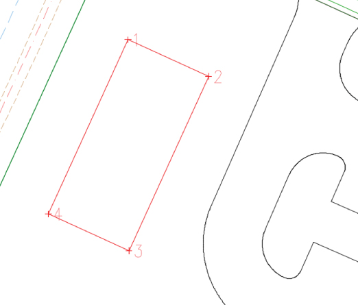
Figure 14.5 Setting the grade between points
This method of creating a feature line by picking each vertex and specifying its elevation or grade before picking the next may seem tedious to some users. In the next portion of the exercise, you will convert an existing polyline to a feature line and acquire elevations for the vertices from a surface.
 From the Home tab Create Design panel, choose Feature Line Create Feature Lines From Objects.
- At the
Select lines, arcs, polylines or 3d polylines to convert to feature lines or [Xref]:prompt, notice the options for selection and note that by typing X and then pressing the Enter key you may pick these types of entities from an external reference. This will save you the trouble of opening the external reference, copy clipping, closing the reference, and pasting to original coordinates. Select the green closed polyline, which represents the edge of the recreation center building. - Press the Enter key.
The Create Feature Lines dialog will appear.
- Verify that Rec Center is the name of the site.
- Verify that the Style check box is filled, and select Grading Building as the style for the feature line using the drop-down.
This Create Feature Lines dialog has some differences from that shown in Figure 14.4. Notably, the Conversion Options near the bottom of the dialog are now active, so take a look at the options presented:
- Erase Existing Entities This option deletes the object and replaces it with a Feature Line object. This avoids the creation of duplicate linework but could be harmful if you wanted to keep your linework for planimetric purposes.
- Assign Elevations This option lets you set the feature line elevations from a surface or grading group, essentially draping the feature line on the selected object.
- Weed Points Weed Points decreases the number of nodes along the object. This option is handy when you're converting digitized information into feature lines.
- Check the Assign Elevations box.
The Erase Existing Entities option is checked by default, and you will not select the Weed Points option.
- Click OK to dismiss the Create Feature Lines dialog.
The Assign Elevations dialog appears. Here you can assign a single elevation for the feature line, assign the elevations from a grading if one is present in the drawing, or select a surface to pull elevation data from.
- Verify that Existing Surface is selected.
- Verify that the Insert Intermediate Grade Break Points option is checked.
This setting inserts a vertical point of intersection (elevation point) at every point along the feature line where it crosses an underlying TIN line.
- Click OK to dismiss the Assign Elevations dialog.
- Select the feature line that was just created, and the grips will look like Figure 14.6.
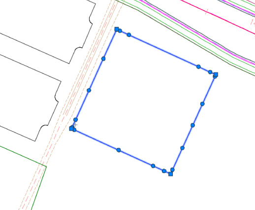
Figure 14.6 Conversion to a Feature Line object
When this exercise is complete, you may close the drawing. A saved copy of this drawing (1401_CreatingFeatureLines_FINISHED.dwg or 1401_CreatingFeatureLines_METRIC_FINISHED.dwg) is available from the book's web page.
Editing Feature Line Information
From the Feature Line contextual tab, you can examine several more commands on the Modify panel, as shown in Figure 14.7, before you get into editing objects.
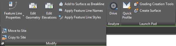
Figure 14.7 The Modify panel on the Feature Line contextual tab
The Modify panel of the Feature Line contextual tab provides commands for editing various properties of the feature line, the feature line style, the feature line geometry, and moving or copying to sites as follows:
- Feature Line Properties The top half of the Feature Line Properties tool is a button that will access the Feature Line Properties dialog. The Feature Line Properties dialog has two tabs: Information and Statistics. The Information tab of the Feature Line Properties dialog allows you to edit the name or feature line style and, if present, remove the dynamic link. The Statistics tab of the Feature Line Properties dialog allows you to view various physical properties such as minimum and maximum grade.
 The bottom half of the Feature Line Properties tool is a drop-down containing two commands:
- Feature Line Properties This command accesses the same Feature Line Properties dialog as discussed earlier when you click the button.
- Edit Feature Line Style This command is used to access various display characteristics of the feature line such as color and linetype. Feature line styles will be discussed further in Chapter 19, “Object Styles.”
 Edit Geometry The Edit Geometry toggle opens and closes the Edit Geometry panel on the Feature Line contextual tab (see Figure 14.8). This panel will remain open until the Edit Geometry button is toggled off (it's highlighted when toggled on). The Edit Geometry panel will be discussed later in this chapter in the “Editing Feature Line Geometry” section.
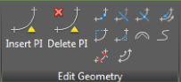
Figure 14.8 The Edit Geometry panel on the Feature Line contextual tab
 Edit Elevations The Edit Elevations toggle opens the Edit Elevations panel on the Feature Line contextual tab (see Figure 14.9). This panel will remain open until the Edit Elevations button is toggled off (it's highlighted when toggled on). The Edit Elevations panel will be discussed later in this chapter in the “Editing Feature Line Elevations” section.
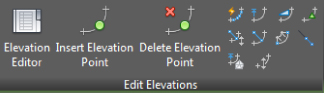
Figure 14.9 The Edit Elevations panel on the Feature Line contextual tab
 Add To Surface As Breakline The Add To Surface As Breakline tool allows you to select a feature line or feature lines to add to a surface as breaklines. Once feature lines are added to the surface, they will be listed as a Breakline Set in Prospector Surface Definition Breaklines.
 Apply Feature Line Names The Apply Feature Line Names tool allows you to apply names to a selection of feature lines based on a new naming template. This tool can be helpful when you want to rename a group or just assign names to feature line objects. This tool cannot be used on a feature lines that are dynamically linked to an alignment and profile, or corridor.
 Apply Feature Line Styles The Apply Feature Line Styles tool changes the styles of selected feature lines.
 Move To Site If you expand the Modify panel, you will notice two additional commands. The first command is Move To Site. This command allows you to associate the selected feature line with a new site.
 Copy To Site The other command in the expanded Modify panel is Copy To Site. This command allows you to duplicate the selected feature with a new site while leaving the original feature line in its current site. The two feature lines are not dynamically linked.
 Once the Feature Line contextual tab has been activated, the Quick Profile tool is available on the Launch Pad panel. The Quick Profile tool generates a temporary profile of the feature line based on user parameters found in the Create Quick Profiles dialog (Figure 14.10).
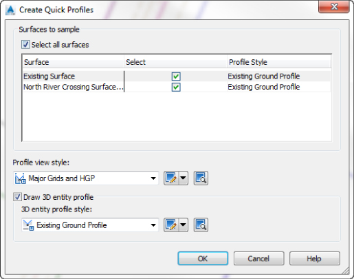
Figure 14.10 The Create Quick Profiles dialog
A few notes on this operation:
- Civil 3D creates a temporary phantom alignment that will not display in Prospector as the basis for a quick profile. A unique alignment number is assigned to this alignment.
- Panorama will display a message to tell you that a quick profile has been generated and to remind you that “this is a temporary object and will be deleted on save command or on exit from drawing.” You can close Panorama or move the Panorama palette out of the way if necessary.
Feature lines aren't the only things from which you can create a quick profile. You can also create a quick profile for 2D or 3D lines or polylines, lot lines, survey figures, or even a series of points. When a quick profile is created from 3D objects, there is an additional option to draw the 3D entity profile.
The Edit Geometry and Edit Elevations toggles provide even more commands, which make them considerably more powerful than standard 3D polylines. The Edit Geometry functions and the Edit Elevations functions are described in the next sections. While these sections reference the Edit Geometry and Edit Elevations panels of the Feature Line contextual tab, these panels are also available on the Modify tab. When used from the Modify tab, many of these commands can also be used to edit parcel lines, survey figures, 3D polylines, and 2D polylines, in addition to feature lines, as discussed in the sections that follow.
Editing Feature Line Geometry
Editing feature-line geometry grading revisions often requires adding PIs, breaking apart feature lines, trimming, and performing other horizontal operations without destroying the vertical information. To access the commands for editing feature-line horizontal information, select the feature line to access the Feature Line contextual tab and toggle on the Edit Geometry panel, as shown in Figure 14.11.
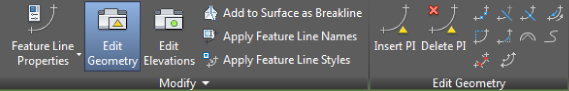
Figure 14.11 The Edit Geometry panel on the Feature Line contextual tab
The first two tools are designed to manipulate the PI points that make up a feature line:
 Insert PI The Insert PI tool allows you to insert a new PI, controlling both the horizontal and vertical design.
 Delete PI The Delete PI tool removes a PI. If the PI is located at the beginning or end of a feature line, the beginning or end segment is removed. If the PI is removed at a PC, the arc is removed and the segment leading into the arc gets stretched to the next PI. If the PI is removed at a PT the arc segment gets stretched to the next PI.
The next few tools act like their AutoCAD counterparts, but they are used specifically with feature lines because elevations are involved and they will add PIs accordingly:
 Break The Break tool allows two feature lines to be created from one. Additionally, if a feature line is part of a surface definition, both new feature lines are added to the surface definition to maintain integrity. Elevations at the new PIs are assigned on the basis of an interpolated elevation.
 Trim The Trim tool operates much like the AutoCAD Trim command, trimming a feature line and adding a new end PI on the basis of an interpolated elevation.
 Join The Join tool creates one feature line from two or more, making editing and control easier. You can set the tolerance distance from the settings associated with the Join tool on the Settings tab of Toolspace by doing the following:
- Expand the Grading Commands branch.
- Right-click JoinFeatures and select Edit Command Settings.
- In the Edit Command Settings - JoinFeatures dialog, expand the Feature Line Join property to change the tolerance.
- Expand the Grading
 Reverse The Reverse tool changes the direction of a feature line and flips any labels applied to the feature line on the opposite side.
 Edit Curve The Edit Curve tool allows you to modify or delete the radius that has been applied to a Feature Line object. Once the feature line is selected, the Edit Feature Line Curve dialog will display. For each curve, you can modify the radius while viewing information on the curve length, chord length, and tangent length. There is also an option to maintain tangency if the curve is not already tangent to attached linework. After entering a value for the radius, a preview of the resulting curve will appear. Values that won't compute will not be accepted. In that case, a warning message will appear. There is also an option to pick two points to define a radius length. You can click the Apply button to continue making edits to other curves of the feature line or click the OK button to complete the command and dismiss the dialog.
 Fillet The Fillet tool inserts a curve at PIs along a feature line and will join feature lines sharing a common PI that are not actually connected. You can apply a radius to a single PI or to all PIs on a feature line.
The last few tools refine feature lines, making them easier to manipulate and use in a surface:
 Fit Curve The Fit Curve tool analyzes a number of elevation points and attempts to define a working arc through them all. This tool is often used when the corridor utilities are used to generate feature lines. These derived feature lines can have a large number of unnecessary PIs in curved areas. You can modify the tolerance and the minimum number of segments by entering O to select Options on the command line during the prompt, and display the Fit Curve Options dialog.
Alternatively, you can set the default values for these options from the settings associated with the Fit Curve tool on the Settings tab of Toolspace by doing the following:
- Expand the Grading Commands branch.
- Right-click FitCurveFeature and select Edit Command Settings.
- In the Edit Command Settings - FitCurveFeature dialog, expand the Feature Line Fit Curve property to change the tolerance and specify the minimum number of segments.
- Expand the Grading
 Smooth The Smooth tool takes a series of disjointed feature line segments and creates a best-fit curve. This tool is great for creating streamlines or other natural terrain features that are known to curve, but there's often not enough data to fully draw them that way. You can also straighten previously smoothed feature lines on the Modify tab Edit Geometry panel by choosing the Smooth command and typing S for Straighten. Notice that the Smooth command accessed through the Feature Line contextual tab does not give you the Straighten option.
 Weed The Weed tool allows the user to remove elevation points and PIs on the basis of various criteria. Once you select the feature line or multiple feature lines or a partial feature line, the Weed Vertices dialog will display. This dialog will allow you to weed based on any combination of angle, grade, or length; in addition, you can remove points based on their 3D distance between one another.
- Weeding by angle considers the horizontal angles at each bend of the feature line and will delete a vertex smaller than the value entered.
- Weeding by grade looks at three points, considering the middle point as a PVI. If the difference in grade is less than the entered amount, the PVI will be deleted.
- Weeding by length looks at three points and will delete the middle point if the distance between the outside points is less than the value entered.
- Weeding by 3D distance looks at the slope distance between two adjacent points and will delete the following vertex if the slope distance is less than the value entered.
-
At the bottom of the Weed Vertices dialog, it states how many of the total number of vertices will be weeded. This is great for cleaning up corridor-generated feature lines as well.
Similar to the Join and Fit Curve tools, you can set the default settings associated with the Weed command on the Settings tab of Toolspace by doing the following:
- Expand the Grading Commands branch.
- Right-click WeedFeatures and select Edit Command Settings.
- In the Edit Command Settings - WeedFeatures dialog, expand the Feature Line Weed property to change the various values.
- Expand the Grading
 Stepped Offset The Stepped Offset tool allows offsetting in a horizontal and vertical direction, making it easy to create stepped features such as stairs or curbs.
In this exercise, you'll manipulate some feature lines that were roughed in to define the pool area at the recreational center:
- Open the
1402_FeatureLineGeometry.dwgor1402_FeatureLineGeometry_METRIC.dwgfile. - Zoom into the area where the sidewalk intersects the edge of the concrete at the southwest edge of the building, and select the edge of the concrete, as shown in Figure 14.12.
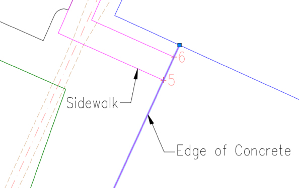
Figure 14.12 Picking the edge of concrete feature line at the southwest edge of the building
 If the Edit Geometry panel isn't visible, from the Feature Line contextual tab Modify panel, choose Edit Geometry to toggle on the Edit Geometry panel.
 From the Feature Line contextual tab Edit Geometry panel, choose the Break tool.
- At the
Select an object to break:prompt, select the edge of concrete feature line again. - At the
Specify second break point or [First point]:prompt, enter F ↵ to pick the first point of the break. - At the
Specify first break point:prompt, using a Node Osnap, select the node of point #5, as shown in Figure 14.13.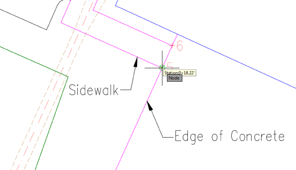
Figure 14.13 Using the node object snap to select a point
- At the
Specify second break point:prompt, using a Node Osnap, select the node of point #6, leaving a gap, as shown in Figure 14.14.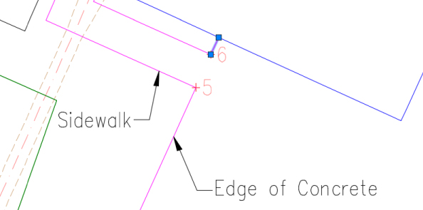
Figure 14.14 The feature line after executing the Break command
The feature lines representing the sidewalk and the edge of concrete at the pool area were roughed in and are not joined. Feature lines that represent continuous line work are much easier to manage when they are joined.
 With the small segment drawn from point #6 to the edge of the building still selected, from the contextual tab Edit Geometry panel, click Join.
- At the
Select the connecting feature line, polyline or 3D polyline or [Multiple]:prompt, select all the magenta feature lines representing the sidewalk and the edge of concrete, as shown in Figure 14.15.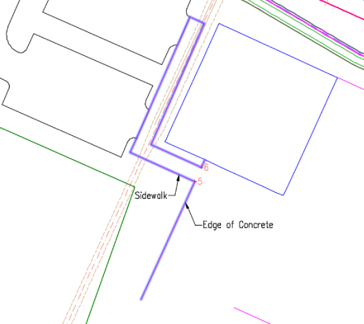
Figure 14.15 Selecting the feature lines representing the sidewalk and edge of concrete
- Press ↵ to end the command.
- Press Esc to deselect.
If you zoom out slightly, you may notice the green feature line representing the edge of pavement that is wrapping around the back of the building. It needs to connect up with the magenta feature line you just joined. Although there is a special Trim command that you must use with feature lines, the AutoCAD Extend command is the tool to use when you need to lengthen feature lines to meet others.
- Execute the AutoCAD Extend command (you can type Ex ↵ at the command line).
- At the
Select boundary edges ... Select objects or <select all>:prompt, select the magenta feature line as the boundary edge. - Press ↵ to advance to the next prompt.
- At the
Select object to extend or shift-select to trim or [Fence Crossing Project Edge Undo]:prompt, select the green feature line to the rear of the building close to the end of the segment that must be extended. - Press Esc to end the command.
The edge of pavement feature line should be extended to the joined feature line as shown in Figure 14.16.
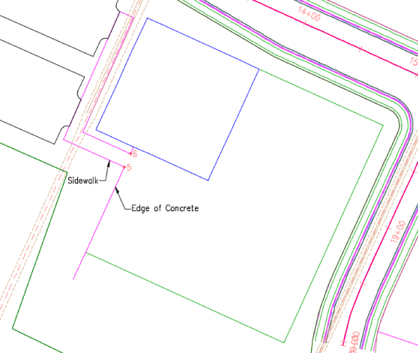
Figure 14.16 The extended edge of pavement feature line
- Select the magenta feature line.
 From the contextual tab Edit Geometry panel, click the Trim tool.
- At the
Select cutting edges:prompt, select the green feature line that was just extended. - Press ↵ to advance to the next prompt.
- At the
Select objects to trim:prompt, select the end of the joined feature line that extends south of the green one. - Press Enter to end the command.
Next you'll join the magenta feature line to the green one. Similar to the AutoCAD Join command, the entity selected first will pass its properties onto those selected after.
- Select the magenta feature line if not already selected.
 From the contextual tab Edit Geometry panel, click the Join tool.
- At the
Select the connecting feature line, polyline or 3D polyline or [Multiple]:prompt, select the green feature line. - Press ↵ to end the command.
- Press Esc to deselect.
At this point in the exercise, your drawing should look like Figure 14.17 containing one feature line representing the edges of the sidewalk joining the edge of concrete around the pool area.
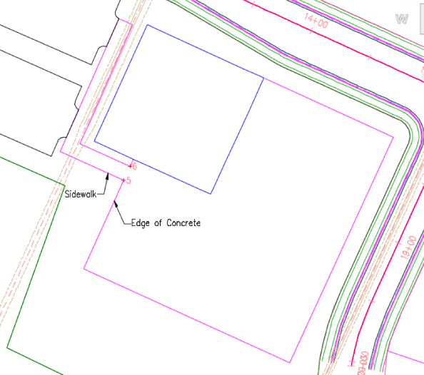
Figure 14.17 One feature line representing the edges of the sidewalk joining the edge of concrete around the pool area
Next, you will round one of the corners of the pool area to accommodate landscape.
- Select the magenta feature line.
 From the contextual tab Edit Geometry panel, click the Fillet tool.
- Hover the cursor over the southwest corner of the magenta feature line, as shown in Figure 14.18.
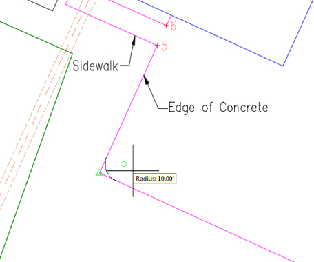
Figure 14.18 Filleting the southwest corner of the magenta feature line
As you hover near the corner, you will see a preview of the fillet with the current radius value following the cursor. Just as with the AutoCAD Fillet command, you could use the options at the command prompt to change the radius value.
- Click near the corner to place the fillet using the default radius value.
- Press Esc twice to end the command and deselect.
To adjust the radius value of the curve, do the following:
- Select the magenta feature line.
To change the radius value of the curve, do the following:
 From the contextual tab Edit Geometry panel, click the Edit Curve tool.
- At the
Select feature line curve to edit or [Delete]:prompt, select the magenta feature line on the curve. - In the Edit Feature Line Curve dialog, type 24′ (8 m) for a new radius value. If you press Tab after entering the radius value, then you can see a preview of the curve before clicking OK.
- Click OK to close the dialog.
- Press Esc to end the command.
- With the feature line still selected, notice the labeled extra PI next to the parking lot.
Sometimes when you piece together your linework, you can end up with extra vertices. Before proceeding to applying elevations to your PIs, you should delete any extras you don't need.
 From the contextual tab Edit Geometry panel, click the Delete PI tool.
You will see triangular glyphs appear at each vertex of the feature line. When your cursor nears a vertex, the glyph turns green indicating that it will be deleted if you click now.
- At the
Specify Point:prompt, hover your cursor over the extra PI and left-click. - Press Esc twice to end the command and deselect.
Your site should now look like Figure 14.19.
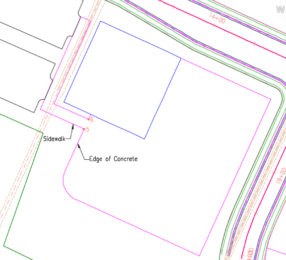
Figure 14.19 Site with completed geometry adjustments
When this exercise is complete, you may close the drawing. A saved copy of this drawing (1402_FeatureLineGeometry_FINISHED.dwg or 1402_FeatureLineGeometry_METRIC_FINISHED.dwg) is available from the book's web page.
Editing Feature Line Elevations
 To access the commands to edit feature line elevation, from the Feature Line contextual tab
 ![]() Modify panel, choose the Edit Elevations toggle to open the Edit Elevations panel.
Modify panel, choose the Edit Elevations toggle to open the Edit Elevations panel.
The first tool in this panel is the Elevation Editor, which will activate a palette in Panorama where you can inspect station, elevation, length, and grade information about the feature line selected in a tabular grid format. You can edit elevation and grade in this interface. When you are working in a row in the Elevation Editor, the corresponding point will be shown with a temporary triangular glyph on the plan.
A number of tools are available for modifying and manipulating feature line elevations. You will be using a few of them in the upcoming exercises. In this first exercise, you'll take a brief look at the Grading Elevation Editor tools:
- Open the
1403_EditingFeatureLineElevations.dwgor1403_EditingFeatureLineElevations_METRIC.dwgfile. - Select the red feature line representing the tennis court area to activate the Feature Line contextual tab.
- On the Feature Line contextual tab Edit Elevations panel, choose the Elevation Editor tool. Then press Esc to deselect the feature so you can observe feature line glyphs while working in the Grading Elevation Editor.
The Grading Elevation Editor in Panorama will open, as shown in Figure 14.20.
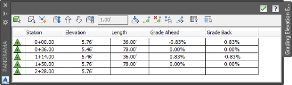
Figure 14.20 The Grading Elevation Editor
A series of symbols appears in the far left column of the Grading Elevation Editor; these are the same glyph symbols used on the feature line grips. A triangular symbol denotes a PI, and a circular symbol denotes an elevation point. In this example, you don't have any elevation points.
- Click in the Station column for the first PI at Station 0+00.00 (or 0+000.00).
As a row is selected in the Grading Elevation Editor, the PI or the elevation point that was selected will be highlighted on the graphic with a small glyph.
You can use the Grading Elevation Editor to make changes to the Station, Elevation, Length, Grade Ahead, and Grade Back settings. The exception is that you cannot edit stationing or length for PI points, as indicated by triangle glyphs in the Grading Elevation Editor.
Across the top of the Grading Elevation Editor are multiple tools that will be used as you edit the data in the table:
 Select Clicking the Select tool allows you to select the feature line on the screen for editing in the Grading Elevation Editor.
 Zoom To The Zoom To tool will do exactly as it says. If a station is highlighted in the Panorama and you select the Zoom To tool, your plan view will be zoomed to that station on the feature line on the screen. When multiple stations are selected, the Zoom To tool will fit those multiple stations into your drawing window.
 Quick Profile The Quick Profile tool will generate a temporary profile based on the feature line selected. This is the same tool discussed earlier that was available on the Feature Line contextual tab Launch Pad panel. The Create Quick Profiles dialog will open, allowing you to select which surface(s) you want to display, as well as what profile view style and 3D entity profile you want.
 Raise/Lower Clicking the Raise/Lower tool will activate the Set Increment text box. This will allow you to raise or lower selected station points, or if no station points are selected, it will raise or lower the entire feature line to the elevation displayed in the text box. This is an actual elevation, not an elevation difference.
 Raise Incrementally and Lower Incrementally The Raise Incrementally/Lower Incrementally tools will raise or lower the station point or points by the amount listed in the Set Increment text box. This is an elevation difference.
 Set Increment The Set Increment tool activates the text box used with the Raise Incrementally and Lower Incrementally tools. This text box must be activated and supplied a value before proceeding with these tools. Negative values are not accepted in the Set Increment text box.
 Flatten Grade Or Elevations The Flatten Grade Or Elevations tool enables you to assign either one elevation to selected station points or a constant slope between selected station points. If you want to flatten the elevations, the elevation of the first selected station point will be applied to the other selected points. If nothing is selected, the elevation of the first point on the list will be used. If you want to apply a constant grade across a selected group of station points, the elevation of the first and last points in the selection will be held and all points in between will be flattened to the grade calculated between the first and last points. When this tool is selected, the Flatten dialog will open asking if you want to flatten by constant elevation or by constant grade.
 Insert Elevation Point The Insert Elevation Point tool will let you select a spot on the feature line and will create an elevation point. The Insert PVI dialog will open, allowing you to fine-tune the station and elevation values.
 Delete Elevation Point The Delete Elevation Point will delete a point or points that are highlighted in the Grading Elevations Editor. Note that this tool will allow you to delete only elevation points.
 Elevations From Surface Clicking the Elevations From Surface tool will open the Select Surface dialog if there are multiple surfaces from which to choose. If you have selected a station point or points, it will assign elevations to only those points. If no station points are selected, the entire feature line will be draped over the surface, assigning elevations to all station points.
 Reverse The Direction The Reverse The Direction tool will do exactly as it says; it will reverse the direction of the feature line, thereby changing the direction of the stationing and the grade ahead/grade back directions.
 Show Grade Breaks Only The Show Grade Breaks Only tool is a toggle (click, it's on, and click, it's off) that will display only the rows where the grade breaks on the feature line. Therefore, if two adjacent segments share the same grade value, the station point that they share will be hidden because the grade doesn't break on that point.
 Unselect All Rows The Unselect All Rows tool does exactly as it says; it will deselect any rows that have been highlighted for editing.
- Click the green check mark in the upper-right corner to dismiss Panorama.
Using the Grading Elevation Editor is the most basic way to manipulate elevation information. Keep this drawing open for use in the next exercise.
Using Other Feature Line Elevation Editing Tools
To access the commands for editing feature line elevation information, select a feature line to access the Feature Line contextual tab and toggle on the Edit Elevations panel, as shown in Figure 14.21. Many of the tools in the Elevation Editor may seem redundant from the Grading Elevation Editor tools discussed earlier, but they are placed here for ease of use.
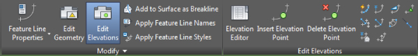
Figure 14.21 The Edit Elevations panel on the Feature Line contextual tab
Moving across the panel beyond the Elevation Editor tool, which was just discussed, you find the following tools for modifying or assigning elevations to feature lines:
 Insert Elevation Point The Insert Elevation Point tool inserts an elevation point at the point selected or multiple elevation points at a specified increment. The elevation occurring on the feature line at the location inserted will be assigned to the elevation point. This elevation can be edited later. Note that elevation points can control only elevation information; an elevation point cannot be moved to alter the original orientation of the feature line.
 Delete Elevation Point The Delete Elevation Point tool deletes the selected elevation point; the points on either side then become connected linearly on the basis of their current elevations. You can also delete all elevation points on a feature line with this command. When deleting an elevation point, the one that will be deleted is highlighted in green.
 Quick Elevation Edit The Quick Elevation Edit tool allows you to use onscreen cues to set elevations and slopes quickly between PIs on any feature lines.
- Hover over a PI or an elevation point and a triangular glyph appears showing the elevation of that station point at the cursor. Click to trigger the prompt at the command line and type in a new elevation.
- Hover over a segment on the feature line and an arrowhead glyph appears showing the direction and grade of the segment. Click to trigger the prompt at the command line and type in a new grade.
 Edit Elevations The Edit Elevations tool steps through the selected feature line, much like working through a polyline edit at the command line, allowing you to change elevations and grades or insert, move, and delete elevation points. A triangular glyph shows up at the current vertex. To skip editing the vertex and move on to the next, press the Enter key to accept the current value.
 Set Grade/Slope Between Points The Set Grade/Slope Between Points tool sets a continuous slope along the feature line between selected points. As you select the points, you will be asked to specify or verify the elevation at each point.
 Insert High/Low Elevation Point The Insert High/Low Elevation Point tool places a new elevation point on the basis of two picked points: the grade ahead of the first point and the grade behind the second point. This calculated point is placed at the intersection of two vertical slopes.
 Raise/Lower By Reference The Raise/Lower By Reference tool allows you to adjust a feature-line station point vertically based on a grade, slope, or elevation difference in relation to a point on another 3D object or point. This relationship isn't dynamic!
 Set Elevation By Reference The Set Elevation By Reference tool at first looks like the same command as the Raise/Lower By Reference tool. The differences are that you can execute this tool on multiple points on the feature line without leaving the command and you can insert new elevation points. This relationship isn't dynamic!
 Adjacent Elevations By Reference The Adjacent Elevations By Reference tool allows you to adjust the elevation of multiple vertices on a feature line by specifying grade, slope, or elevation difference from another 3D object. If the 3D object has length, elevations are projected to the feature-line station points perpendicularly from the 3D object. This relationship isn't dynamic!
 Grade Extension By Reference The Grade Extension By Reference tool allows you to set the grade, slope, or elevation difference between feature line segments across a gap. For example, you might use this tool along the back of curbs at locations such as driveways or intersections. This relationship isn't dynamic!
 Elevations From Surface The Elevations From Surface tool sets the elevation at each PI and elevation point on the basis of the selected surface. It will optionally add elevation points at any point where the feature line crosses a surface TIN line.
 Raise/Lower The Raise/Lower tool simply moves the entire feature line in the z direction by an amount entered at the command line. A positive number raises and a negative number lowers.
Some of the tools can be difficult to understand, so you'll look at them in the next exercise and see how they function in some basic scenarios:
- If not opened for the previous exercise, open the
1403_EditingFeatureLineElevations.dwgor1403_EditingFeatureLineElevations_METRIC.dwgfile. You do not need to have completed the previous exercise to proceed. - Zoom into the entrance to the parking lot of the site.
Notice that the corridor has been cleaned up at the entrance. A region was inserted and an assembly was used that omitted the curb, gutter, and sidewalk in the entrance area. To review regions and the use of multiple assemblies in a corridor, see Chapter 10, “Advanced Corridors, Intersections, and Roundabouts.”
Also, two feature lines were extracted from the corridor representing the flowline at the curb and gutter on both sides of the region. They are dynamically linked to the corridor so they will update if the corridor is modified. To review the Feature Lines From Corridor command, see Chapter 9.
- On the Prospector tab, expand the Sites Parking Lot collection.
- Right-click Feature Lines and select Properties from the context menu.
- In the Feature Line Site Properties dialog on the Options tab, do the following:
- Fill in the Filter Unused Styles check box.
Only the styles in use will display.
- Highlight the Corridor Grading style.
 Click the up arrow button a number of times to move the Corridor Grading feature line style to the top of the list, as shown in Figure 14.22.
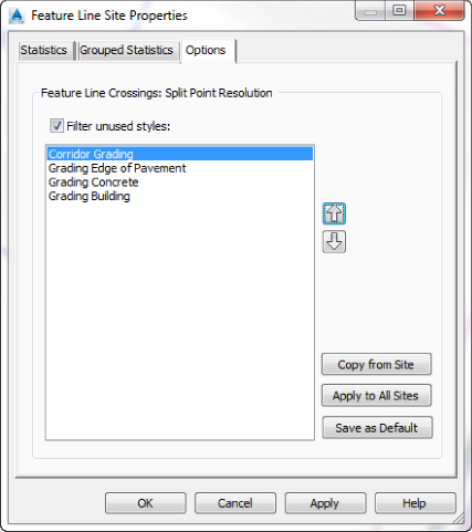
Figure 14.22 Assigning priority in the Feature Line Site Properties dialog
This will set the initial priority by style when feature lines cross where no PIs exist. This means that the feature line style that is higher on the list will set the elevation where it intersects another. If the feature lines have the same style applied, the one modified last will win.
- Click OK to close the dialog.
- Fill in the Filter Unused Styles check box.
- Select the white polyline representing the edge of pavement of the parking lot.
- On the Home tab Create Design panel Feature Line drop-down, select Create Feature Lines From Objects.
- In the Create Feature Lines dialog, do the following:
- Set the Site to Parking Lot.
- In the Style area, use the drop-down to set the Style to Grading Edge Of Pavement.
- Under Conversion Options, clear the check box for Assign Elevations And Weed Points. The Erase Existing Entities check box should remain checked.
- Click OK to close.
- Select the newly created feature line.
- On the contextual tab Edit Elevations panel, select the Elevation Editor tool.
- Scroll through the Grading Elevation Editor to review it.
Notice that the elevations of the feature line at stations 0+00 and 9+21.75 (0+000 and 0+280.97 if metric) are already set because these stations were touching the extracted corridor feature lines when the polyline was converted. The feature line is matching grade with the road at the flowline on both sides of the entrance.
- Leave the Grading Elevation Editor open. Either push it to the side or minimize it.
 With the feature line still selected, on the contextual ribbon Edit Elevations panel, click Quick Elevation Edit.
- Hover over the middle of the left curb return. Use your scroll button to zoom in or out if necessary.
Notice the triangular glyph that appears on the segment, which changes directions depending on which end of the segment your cursor is nearest. The direction in which the triangle is pointing is the direction in which you will be applying the grade. Notice that the triangular glyph turns gray when it points to where the edge of pavement feature line touches the corridor's dynamically linked feature line. This glyph indicates that this elevation is being influenced by another feature line.
- Position the cursor so that the triangular glyph is pointing toward the parking lot, as shown in Figure 14.23, and left-click.
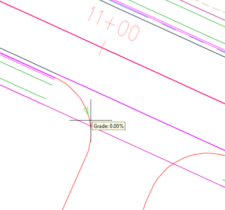
Figure 14.23 Editing the grade of a feature line with Quick Elevation Edit
- At the
Specify grade or [Slope]:prompt, type 3 ↵ to specify a 3 percent grade. - Go to the Grading Elevation Editor and scroll to the bottom of the list to look at the elevation assigned at station 8+90.59 (0+271.46 if metric).
- With the Quick Elevation Edit tool still running, hover over the PT of the right curb return of the entrance.
A tooltip showing elevation will appear with an equilateral triangular glyph, as shown in Figure 14.24. With the Quick Elevation Edit tool, not only can you edit the grade or slope of a feature line segment, but you can also edit the elevation of a PI.
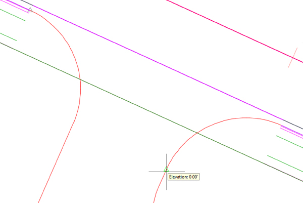
Figure 14.24 Editing the elevation of a feature line with Quick Elevation Edit
- Click over the PI.
- At the
Specify elevation or [Surface]:prompt, type 7.07 (2.151 if metric). - Check the Grading Elevation Editor at station 0+31.70 (0+009.67 if metric), and notice that the elevation you just typed in has been assigned to the second station on the list.
- Leave the Grading Elevation Editor open.
- Press Esc twice to end the command and deselect.
- Hover over the middle of the left curb return. Use your scroll button to zoom in or out if necessary.
- Pan over to the Building feature line and select.
Previously, you used the Elevations From Surface tool to assign elevations to the feature line. You also had the Insert Intermediate Grade Break Points check box filled. Figure 14.25 displays how the Set Elevations From Surface dialog was configured in the previous exercise.
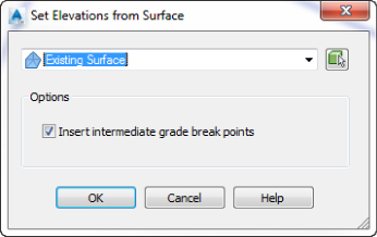
Figure 14.25 Set Elevations From Surface dialog
The circular grips called elevation points on the feature line are there because TIN lines from the surface crossed the feature lines at those locations. You will remove the elevation points from the feature line so you can set elevations at just the four corners of the building for now.
- With the feature line still selected, on the contextual tab Edit Elevation panel, select Delete Elevation Point.
- As the cursor nears the feature line, circular glyphs appear where the circular grips are located and triangular glyphs appear at the four corners. This tool will remove only the circular glyphs (elevation points).
- At the
Specify point or [All]:prompt, type A ↵. - Press Esc to end the command.
If you take a look at the Grading Elevation Editor on Panorama, you may notice that it is still displaying the numerous stations associated with the parking lot feature line. The Grading Elevation Editor will not automatically change its contents based on the current selection.
- At the
 In the Grading Elevation Editor tab on Panorama, do the following:
- Click the Select A Feature Line, Parcel Line, or Survey Figure tool, the green button in the upper-left corner of Panorama.
Since the feature line was still selected when you clicked the tool, the Grading Elevation Editor instantly updated.
- Select all the PIs by selecting the first line, then holding the Shift key down, and selecting the last line.
- Click into one of the elevation fields and enter 8 (2.5 for metric) to set the initial elevation of each PI outside the building.
- Click the Select A Feature Line, Parcel Line, or Survey Figure tool, the green button in the upper-left corner of Panorama.
- In the Grading Elevation Editor tab on Panorama, click the Select A Feature Line, Parcel Line, or Survey Figure tool.
- Using the pick box, select the magenta feature line representing the edge of the concrete around the pool area.
Notice that an elevation has been assigned to the beginning station of the feature line at point 1. Since the edge of concrete feature line intersects the building feature line, they are sharing the same elevation. The final station near the northeast corner of the building at point 8 should be set by the building feature line, but it is still at elevation 0. Zooming in closer to this area will reveal that the feature line doesn't quite intersect the building. Since you need the PI of the building and the PI of the edge of concrete to match elevations at this location, you will connect them.
- Click the magenta feature line, click the grip of the PI near point 8, and Endpoint Osnap it to the northeast building corner.
The Grading Elevation Editor will update, as shown in Figure 14.26. Notice the + sign near the bottom-right corner of the green triangle in the first and last rows? That shows that the feature lines touch.
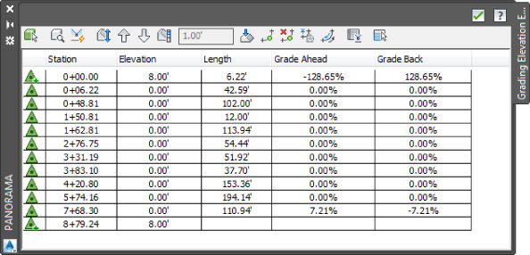
Figure 14.26 Updated Grading Elevation Editor after grip-editing the edge of concrete feature line
- Close Panorama by clicking the green check mark in the upper-right corner.
Next, you'll set the grades on the edge of concrete feature line. The object is to get the runoff to flow away from the building toward the southern end of the site.
 Select the magenta feature line and on the contextual ribbon Edit Elevation tab, select Set Elevation By Reference.
- At the
Specify reference point:prompt, Endpoint Osnap to the northeast corner of the building at point 8. - At the
Specify point or [Insert]:prompt, hover over the northeast corner of the edge of concrete near point 7 and left-click (there is no need to use Osnaps), as shown in Figure 14.27.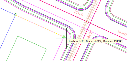
Figure 14.27 Using Set Elevation By Reference to grade the edge of concrete
- At the
Specify grade or [Slope Difference]:prompt, type –0.5 ↵ for grade.The command will repeat itself so you can select another point to be graded relative the reference point selected when the command launched.
- At the
- On the contextual ribbon Edit Elevation tab, select Set Elevation By Reference to reset the command.
- At the
Specify reference point:prompt, Endpoint Osnap on the northeast corner of the edge of concrete at point 7 (the point you just assigned an elevation to). - At the
Specify point or [Insert]:prompt, click the southeast corner of the edge of concrete at point 6. - At the
Specify grade or [Slope Difference]:prompt, type -0.5 ↵ for grade.
- At the
- On the contextual ribbon Edit Elevation tab, select Set Elevation By Reference to reset the command.
- At the
Specify reference point:prompt, Endpoint Osnap on first PI of the magenta feature line at point 1 on the south side of the building, as shown in Figure 14.28.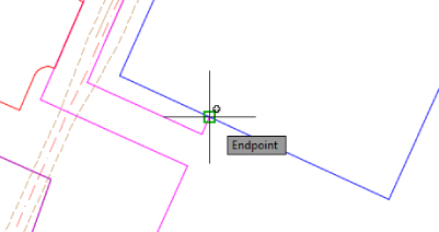
Figure 14.28 Using Set Elevation By Reference on the south side of the building
- At the
Specify point or [Insert]:prompt, click the next PI on the magenta feature line at point 2. - At the
Specify grade or [Slope Difference]:prompt, type –1 ↵ for grade. - At the
Specify point or [Insert]:prompt, click the PI on the magenta feature line at point 3. - At the
Specify grade or [Slope Difference]:prompt, type –1 ↵ for grade. - At the
Specify point or [Insert]:prompt, click the PC on the magenta feature line at point 4. - At the
Specify grade or [Slope Difference]:prompt, type –1 ↵ for grade. - Press Esc to end the command.
- At the
- On the contextual ribbon Edit Elevation tab, select Elevation Editor.
In the Grading Elevation Editor, note that stations 0+48.81 through 2+76.75 (0+015.48 through 0+084.96 if metric) are still at elevation 0. These PIs occur in the sidewalk area and you'll grade them later. Station 4+20.80 (0+129.26 if metric) occurs at the PT at point 5. You'll apply a continuous grade between points 4 and 6.
- Select stations 3+83.10 through 5+74.16 (0+116.69 through 0+175.32 if metric) in the Grading Elevation Editor.
 Select the Flatten Grade Or Elevations tool at the top of the Grading Elevation Editor.
- In the Flatten dialog, select Constant Grade and click OK to assign.
According to the Grading Elevation Editor, a grade of –0.43 has been assigned. Now you'll set a lowpoint at the midpoint of the segment between points 5 and 6.
- Close the Grading Elevation Editor. The magenta feature line should still be selected.
- On the contextual ribbon Edit Elevation tab, select Insert High/Low Elevation Point.
- At the
Specify the start point:prompt, select the PI at point 6. - At the
Specify the end point:prompt, select the next PI at point 5.A triangular directional glyph appears near the last point picked, indicating the direction the grade will be applied.
- At the
Specify grade ahead or [Slope]:prompt, type –1 ↵.A triangular directional glyph appears now near the first point picked indicating the direction the next grade will be applied.
- At the
Specify grade back or [Slope]:prompt, type –0.5 ↵.The location of the lowpoint is calculated with the grades provided and a circular elevation point is inserted at that location, as shown in Figure 14.29.
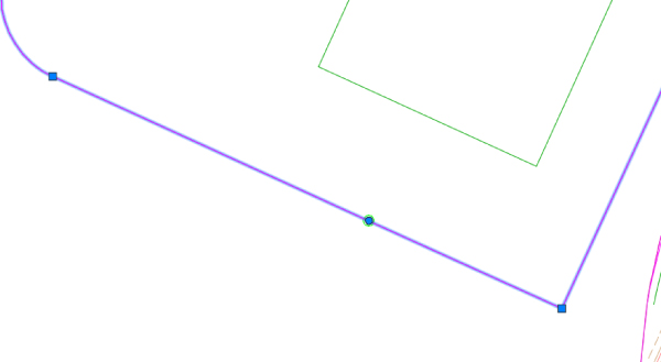
Figure 14.29 Location of elevation point calculated with the Insert High/Low Elevation Point tool
- Press Esc twice to end the command and deselect.
To set the grades on the sidewalk, you will get a little crafty. You'll create a temporary surface that defines a grade of 2percent away from the building. Then you'll assign elevations to the sidewalk area with this surface. You will do something similar later in the next section using grading groups.
- At the
- Select the building feature line and on the contextual ribbon Edit Geometry tab, select Stepped Offset.
- At the
Specify offset distance or [Through Layer]:prompt, type 25 (8 if metric) ↵. - At the
Specify side to offset or [Multiple]:prompt, pick a point outside the building area. - At the
Specify elevation difference or [Grade Slope Elevation Variable]:prompt, type G ↵ to specify grade. - At the
Specify grade or [Slope Elevation Difference Variable]:prompt, type –2 ↵. Press Esc twice.
- At the
- Select the new feature line, and on the contextual tab, expand the Modify panel to select Move To Site.
- In the Move To Site dialog under Destination Site, select Temp.
- Click OK to close.
Leaving the new feature line in the same site as the edge of concrete and building feature line would have caused an elevation point to have been inserted wherever it crossed over these feature lines. Moving it to another site keeps that from occurring.
- Select the building feature line and the new offset feature line.
- On the contextual tab Modify panel, click the Add To Surface As Breakline tool.
 In the Select Surface dialog, click the plus sign button to create a new surface.
- In the Create Surface dialog, type Temp for the surface name.
- For Style, click into the Style value field. Then click the ellipsis button to open the Select Surface Style dialog.
- In the Select Surface Style dialog, select the style called Border Only and click OK to close.
- Click OK to close the Create Surface dialog.
- Click OK to close the Select Surface dialog, and the Add Breaklines dialog opens.
- Under Supplementing Factor, fill in the Distance check box.
- In the Distance field, type 25 (8 if metric).
Creating surface points at this frequency will produce a set of uniform triangles across the sidewalk area, which makes for a more accurate surface.
- Click OK to close, and press Esc to deselect the feature lines.
- Select the magenta feature line, and on the contextual tab Edit Elevations panel, click Elevation Editor.
- In the Grading Elevation Editor, select all the PIs with an elevation value of 0 by holding down the Shift key during the selection.
- At the top of the Grading Elevation Editor, click the Elevations From Surface tool.
- In the Select Surface dialog, select the Temp surface using the drop-down and click OK.
- Click the green check mark in the Grading Elevation Editor to close it, and press Esc to deselect the feature line.
Last, you will make an adjustment to the red feature line on the west side of the site representing the tennis court. As you may recall, the northwest corner was set by acquiring its elevation from the existing surface, and then from that corner typical cross slopes were applied. You will now raise the tennis court to ensure that it will be higher than the surrounding ground.
- Select the red feature line representing the tennis court and on the contextual tab Edit Elevations panel, click the Raise/Lower tool.
- At the
Specify Elevation Difference:prompt, type 0.5 (0.15 for metric) ↵. - Press Esc to deselect.
- At the
When this exercise is complete, you may close the drawing. A saved copy of this drawing (1403_Editing FeatureLineElevations_FINISHED.dwg or 1403_Editing FeatureLineElevations_METRIC_FINISHED.dwg) is available from the book's web page.
You are halfway to completing the construction of your grading model. In an upcoming section, you will use another grading tool called Grading Groups to assign elevations in the parking lot. By using all the tools in the Feature Lines toolbar, you can quickly grade elements of your design and pull them together in a surface.
Labeling Feature Lines
Feature lines can be labeled with their overall length, segment length, vertex elevation, and segment grade or slope. This is helpful to the designer because as you change your design, you can monitor geometry values, grades, and elevations since the labels update as you go. In the next couple of exercises, you'll label a few critical points on your site design to help you better understand the drainage patterns.
Feature lines do not have their own unique label styles, but they do use Line and Curve labels under General styles. You can learn more about label styles in Chapter 18, “Label Styles.” The templates that ship with Civil 3D contain styles for labeling segment slopes, so you'll label the grades of feature line segments in the following exercise:
- Open the
1404_LabelingFeatureLines.dwgor1404_LabelingFeatureLines_METRIC.dwgfile. - From the Annotate tab Labels & Tables panel, click the Add Labels icon to display the Add Labels dialog.
- In the Add Labels dialog, do the following:
- Set the Feature drop-down to Line And Curve.
- Set Label Type to Single Segment.
- Set Line Label Style to Feature Line Info.
- Set Curve Label Style to Feature Line Info.
When complete, the dialog should look like Figure 14.30.
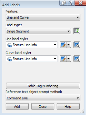
Figure 14.30 Adding feature line grade labels
- Click the Add button.
- At the
Select point on entity:prompt, pick the several segments on the magenta feature line, as shown in Figure 14.31.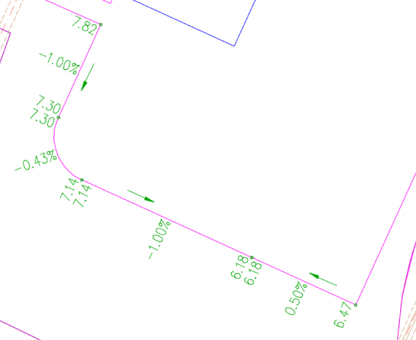
Figure 14.31 Feature line grade labels in the Imperial drawing
You can also try to change the slopes of some of the segments in Elevation Editor to see what happens to the labels.
When this exercise is complete, you may close the drawing. A saved copy of this drawing (1404_LabelingFeatureLines_FINISHED.dwg or 1404_LabelingFeatureLines_METRIC_FINISHED.dwg) is available from the book's web page.
Grading Objects
Once a feature line is created for site grading, there are two main uses. One is to incorporate the feature line itself directly into a surface object as a breakline; the other is to create a grading object (referred to hereafter as simply a grading or gradings) using the feature line as a baseline. A grading consists of a baseline and grading criteria, which describes how a slope projects from the baseline feature line. This slope can be defined by two of the following: distance, slope or grade, relative elevation, or actual elevation. Surfaces can also be part of the criteria. Grading criteria can be defined and stored in grading criteria sets for ease of management. Styles can be applied to gradings for visual preferences or to convey information such as cut or fill.
Gradings are stored on Prospector within Sites in a branch called Grading Groups. They must be created in the same site as their originating feature lines. Gradings produce feature lines along the limits of each projected slope. These feature lines, like corridor feature lines, cannot be edited. They can be added to surfaces and also used to create other gradings. When these grading-dependent feature lines are used to create other gradings, the additional gradings become part of the grading group. These gradings are joined and will change when the baseline feature line or a parent grading is modified.
In this section, you'll use a number of methods to create gradings, edit those gradings, and finally convert the grading group into a surface.
Creating Gradings
Let's look at grading a pond. In this section, you'll look at grading groups and then create the individual gradings within the group. Grading groups act as a collection mechanism for dependent gradings, and they let Civil 3D keep track of which gradings are to act in sync with each other.
One thing to be careful of when you're working with gradings is that they are part of a site. Any feature line within that same site will react with the feature lines created by the grading. For that reason, the exercise drawing has another site called Pond Grading to be used for just pond grading.
- Open the
1405_GradingThePond.dwgor1405_GradingThePond_METRIC.dwgfile. - Select the feature line representing the edge of pond to activate the Feature Line contextual tab.
- From the Feature line contextual tab expand the Modify panel, and choose Move To Site to display the Move To Site dialog.
- Set the Destination Site drop-down to the site named Pond Grading and click OK.
This will avoid interaction between the pond gradings and any other feature lines in the drawing.
 With the feature line still selected, on the Feature Line contextual tab Launch Pad panel, choose Grading Creation Tools.
The Grading Creation Tools toolbar, shown in Figure 14.32, appears. The left section is focused on settings, the middle on creation, and the right on editing.
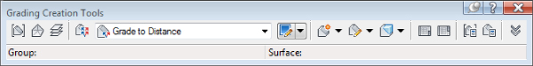
Figure 14.32 The Grading Creation Tools toolbar
 On the Grading Creation Tools toolbar, click the Set The Grading Group tool to the far left of the toolbar to display the Site dialog.
- Choose the Pond Grading site from the drop-down list and click OK.
The Create Grading Group dialog is displayed.
- Enter Pond Grading in the Name text box, as shown in Figure 14.33, and click OK.
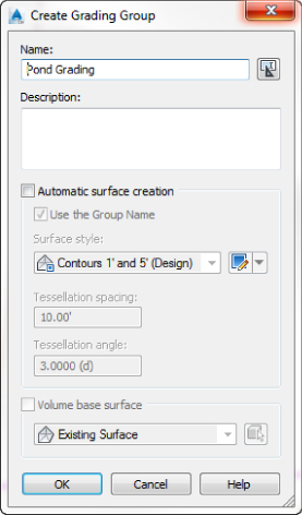
Figure 14.33 Assign the name Pond Grading in the Create Grading Group dialog
You'll revisit the surface creation options in a bit.
 On the Grading Creation Tools toolbar, click the Select Target Surface tool located next to the Select Grading Group tool to display the Select Surface dialog.
- Select Existing Surface and click OK.
 On the Grading Creation Tools toolbar, verify that Grading Criteria is set to Grade To Distance and click the Create Grading tool, or click the down arrow next to the Create Grading tool and select Create Grading, as shown in Figure 14.34.
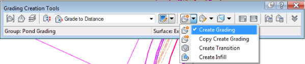
Figure 14.34 Creating a grading using the Grade To Distance criteria
- At the
Select the feature:prompt, select the pond feature line. If you get a dialog asking you to weed the feature line, select the Continue Grading Without Feature Line Weeding option. - At the
Select the grading side:prompt, pick a point on the inside of the pond basin to indicate the direction of the grading projections. - At the
Apply to entire length? [Yes No]:prompt, enter Y ↵ to apply the grading to the entire length of the pond outline. - At the
Specify distance:prompt, enter 5 ↵ (or 1.5 ↵ for metric users) at the command line as the distance. - At the
Format [Grade Slope]:prompt, enter S ↵. - At the
Slope:prompt, enter –10 ↵ for a 10 horizontal to 1 vertical slope.The first grading has been created. The lines onscreen are part of the Grading style.
- Press Esc to end the command.
Gradings can be modified with the Grading Editor. In the Grading Editor, you can edit any of the criteria you used to apply the grading slopes.
- Click the diamond-shaped glyph located inside the grading you just created.
 On the contextual tab Modify panel, click Grading Editor.
Panorama opens displaying the Grading Editor.
- On the Grading Editor tab under the Grading Method parameter group, click in the Distance Value field and type in a new distance value of 10 (or 3 for metric users).
- Click the green check mark to dismiss the vista.
Now you will attach more gradings to complete the pond design.
- On the Grading Creation Tools toolbar, set Grading Criteria to Grade To Elevation, and click the Create Grading tool.
- At the
Select the feature:prompt, select the inner boundary of the grading made in step 17. - At the
Apply to entire length? [Yes/No]:prompt, enter Y ↵ to apply to the whole length. Notice that you did not have to select a side, because there is already a grading object on one side of the selected feature line. - At the
Elevation:prompt, enter 1 ↵ (0.3 ↵ for metric users) for the target distance to build the safety ledge. - At the
Cut Format [Grade Slope]:prompt, enter S ↵. - At the
Slope:prompt, enter 3 ↵. - At the
Fill Format [Grade Slope]:prompt, enter S ↵. - At the
Slope:prompt, enter 3 ↵. - Press Esc to end the command. Your pond should look like Figure 14.35.
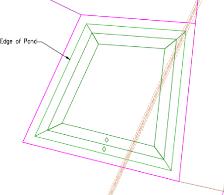
Figure 14.35 Creating a grading group
- On the Grading Creation Tools toolbar, set Grading Criteria to Grade To Surface, and click the Create Grading tool.
- At the
Select the feature:prompt, select the edge of pond feature line. - At the
Select the grading side:prompt, click outside the feature line. - At the
Apply to entire length [Yes No]?prompt, enter Y ↵. - At the
Cut Format [Grade Slope]:prompt, enter S ↵. - At the
Cut Slope:prompt, enter 3 ↵ for a 3 horizontal to 1 vertical slope. - At the
Fill Format [Grade Slope]:prompt, enter S ↵. - At the
Fill Slope:prompt, enter 3 ↵ for a 3 horizontal to 1 vertical slope. - Press Esc to end the command.
Your drawing should look similar to Figure 14.36.
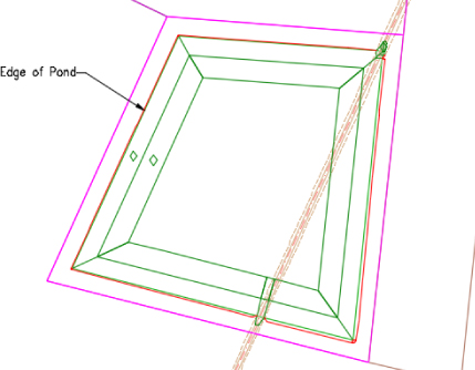
Figure 14.36 Feature line grading for the pond
- On the Grading Creation Tools toolbar, click the down arrow next to the Create Grading tool and select Create Infill.
An infill is a grading that is used to fill in holes.
- Click in the open area in the middle of the pond.
- Press Esc to end the command. Next, you will check the pond volume to make sure it meets the capacity needed.
- On Prospector, expand the Sites Pond Grading Grading Groups branches, select Pond Grading, right-click, and choose Properties.
- In the Grading Group Properties dialog, fill in the check box for Automatic Surface Creation.
The Create Surface dialog opens.
- Click OK to accept the defaults in the Create Surface dialog.
- Back in the Grading Group Properties dialog, fill in the check box under Volume Base Surface and verify that Existing Surface is selected.
A surface was previously created using the edge of pond feature line for the purpose of running this analysis. The Grading Group Properties dialog should be set as shown in Figure 14.37.
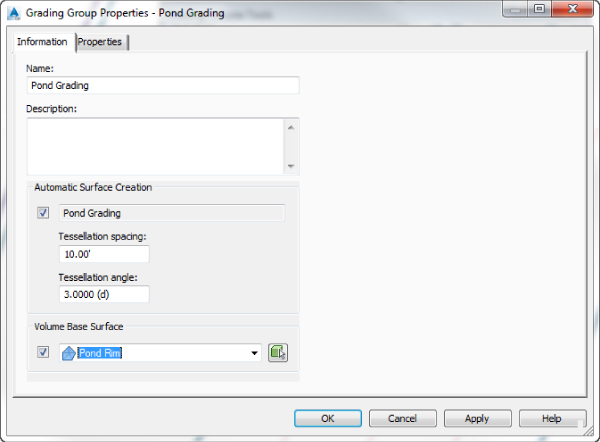
Figure 14.37 Configure the Grading Group Properties.
- Click OK to close the dialog.
- Up on the ribbon on the Analyze tab Volumes And Materials panel, choose Grading Volume Tools.
The Grading Volume Tools toolbar opens. Note the value for Cut: 2657.30 cubic yards (3278.89 cubic meters). This represents the total volume that this pond can hold.
 Click the Lower The Grading Group button in the Grading Volume Tools.
This action just lowered the pond by the amount that is entered in the white field on the right side of the box. Notice that the Cut value has increased, which means the pond's capacity has increased: 3079.79 cubic yards (4866.26 cubic meters).
When this exercise is complete, you may close the drawing. A saved copy of this drawing (1405_GradingThePond_FINISHED.dwg or 1405_GradingThePond_METRIC_FINISHED.dwg) is available from the book's web page.
Each piece of this pond is tied to the next, creating a dynamic model of your pond design on the basis of the designer's intent. Next, you will learn how to use grading groups to help grade the parking lot.
Using Gradings for Interim Surfaces
An interim surface is like a temporary surface in a way. It's a surface that is built for the purpose of extracting elevations. It's a stepping-stone to getting to the final solution. The Temp surface you built around the building a few exercises ago was an interim surface.
In this exercise, you will take a feature line and add a grading to both sides that projects outward at an upward slope of 1 percent. Then you will use the Elevations From Surface command to assign the elevations to portions of the parking lot feature line.
- Open the
1406_GradingsAndInterimSurfaces.dwgor1406_GradingsAndInterimSurfaces_METRIC.dwgfile.A bio-retention area will be placed between the two parking areas. The grading concept is to direct the flow toward the green feature line between the parking areas.
- Select the green feature line between the parking areas.
- On the contextual tab Launch Pad panel, select Grading Creation Tools.
 On the Grading Creation Tools toolbar, click Set The Grading Group.
- Set the Site Name to Temp2.
 Click the Create A Grading Group button and in the Create Grading Group dialog under Name, enter Temp2.
- Fill the check box next to Automatic Surface Creation.
- Set the Surface Style to _No Display.
- Click OK to close.
- Click OK to accept the defaults in the Create Surface dialog.
- Click OK to close the Select Grading Group dialog.
- On the Grading Creation Tools toolbar, set Grading Criteria to Grade To Distance.
 On the Grading Creation Tools toolbar, click the Create Grading button.
- At the
Select the feature:prompt, click the green feature line between the parking areas. - At the
Select the grading side:prompt, click to the north side of the feature line. - At the
Apply to entire length? [Yes No]:prompt, enter Y ↵. - At the
Specify distance:prompt, enter 80 (25 if metric) ↵. - At the
Format [Grade Slope]:prompt, enter G ↵. - At the
Grade:prompt, enter 1 ↵. - Repeat steps 7 through 11 for the south side of the feature line.
- Press Esc to end the command and close the Grading Creation Tools.
You now have an interim grading group surface built over the parking area, as shown in Figure 14.38.
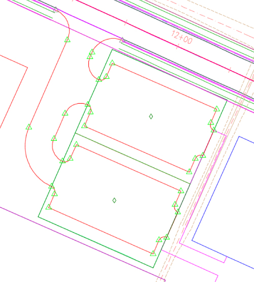
Figure 14.38 A grading group used as an interim surface built over the parking lot
- Select the red feature line representing the edge of the parking lot.
- On the contextual tab Edit Elevations panel, select Elevation Editor.
- Using the Shift key, select stations 0+59.82 through 3+67.24 (0+018.24 through 0+111.94 if metric).
 At the top of the Grading Elevation Editor, click the Elevations From Surface tool.
- In the Select Surface dialog, choose Temp2.
- Click OK to close.
- Repeat steps 17 through 20 for stations 4+38.36 through 7+45.78 (0+133.62 through 0+227.32 if metric).
- In the Grading Elevation Editor, select stations 0+31.70 through 0+59.82 (0+009.67 through 0+018.24 if metric).
 Click the Flatten Grades Or Elevations button.
- In the Flatten dialog, select Constant Grade.
- Click OK to close.
- Repeat steps 22 through 25 for the following station ranges:
- 3+67.24 through 4+38.36 (0+111.94 through 0+133.62 if metric)
- 7+45.78 through 8+90.59 (0+227.32 through 0+271.46 if metric)
The Grading Elevation Editor should look something like Figure 14.39.
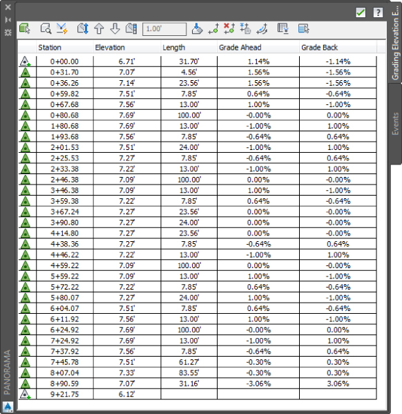
Figure 14.39 Grading Elevation Editor after applying elevations from interim surface
When this exercise is complete, you may close the drawing. A saved copy of this drawing (1406_GradingsAndInterimSurfaces_FINISHED.dwg or 1406_GradingsAndInterimSurfaces_METRIC_FINISHED.dwg) is available from the book's web page.
Finishing Touches
You've just completed some basic grading tasks focusing on the tennis courts, building and pool area, pond, and parking area as separate components. Now it is time to bring the components together in a finished grade surface model. Once the surface model is created, you'll be able to see which areas will need further attention.
- Open the
1407_FinishingTouches.dwgor1407_FinishingTouches_METRIC.dwgfile.The sidewalk grades were set from a surface (Temp) that was created by projecting a slope of 2 percent downward and away from the building. The parking lot elevations at the four PIs that coincide with the edge of sidewalk were set by another method. You want these elevations to match. So you will apply the elevations from the surface called Temp to these PIs.
- Select the parking lot feature line.
- On the contextual tab Edit Elevations panel, select Elevation Editor.
- With the Shift key, select stations 2+01.53 through 2+25.53 (0+061.43 through 0+068.75 if metric).
- At the top of the Grading Elevation Editor, click the Elevations From Surface tool.
- In the Select Surface dialog, choose Temp.
- Click OK to close.
- Repeat steps 4 through 7 for stations 5+80.07 through 6+04.07 (0+176.81 through 0+184.13 if metric).
- Close the Grading Elevation Editor.
- Select the feature lines representing the tennis court (red), the parking lot (red), the edge of concrete (magenta), the building (blue), and the pool (green).
- On the contextual tab Modify panel, select Add To Surface As Breakline.
 In the Select Surface dialog, click the plus sign to add a surface.
- In the Create Surface dialog, enter Finished Grade for the surface name.
- Click OK to close the Create Surface dialog.
- Click OK to close the Select Surface dialog.
- In the Add Breaklines dialog, do the following:
- Enter Site Features for Description.
- Under Supplementing Factors, fill the Distance check box and configure a supplementing distance of 25′ (8 m if metric).
- Under Mid-ordinate Distance, enter 0.1’ (0.03 m if metric).
- Click OK to close the Panorama Event Viewer.
- Press Esc to deselect.
You have just set up your finished grade surface model. To make it even more user friendly, add some surface labels.
- Select the surface by clicking the green surface border.
- On the contextual tab Labels & Tables panel, select Add Labels Spot Elevations.
- Click the building corners, pavement corners, sidewalk corners, and any other location where you'd like a reading on the elevation value. Press Esc twice when you have finished placing spot elevations.
Your drawing should look something like Figure 14.40.
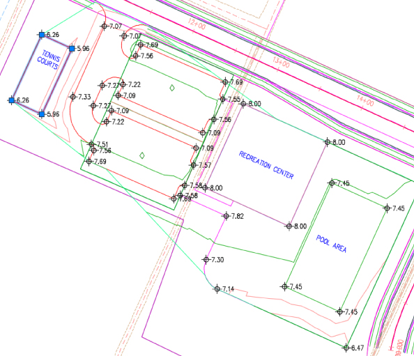
Figure 14.40 Finished grade surface model with dynamic elevation labels
Now that the model is built, you can see how the different feature lines are contributing to the surface grades and can make some adjustments.
- On Prospector, expand the Surfaces branch.
- Right-click Finished Grade and select Rebuild - Automatic.
It appears that the grade for the tennis courts was set too low.
- Select the red feature line representing the tennis courts.
- On the contextual tab Edit Elevations tab, select Raise/Lower.
- At the
Specify elevation difference:prompt, enter 1.5 (0.5 if metric) ↵.The surface updates, as shown in Figure 14.41.
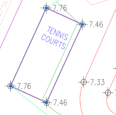
Figure 14.41 Updated surface after raising the tennis courts feature line
You can use any of the tools that were introduced to you in the chapter on the feature lines for this site to add high/low points or adjust elevations and grades. Feel free to experiment further with this file.
When this exercise is complete, you may close the drawing. A saved copy of this drawing (1407_GradingFinishingTouches_FINISHED.dwg or 1407_GradingFinishingTouches_METRIC_FINISHED.dwg) is available from the book's web page.
The Bottom Line
- Convert existing linework into feature lines. Many site features are drawn initially as simple linework for the 2D plan. By converting this linework to feature line information, you avoid a large amount of rework. Additionally, the conversion process offers the ability to drape feature lines along a surface, making further grading use easier.
- Master It Open the
MasterIt_1401.dwgorMasterIt_1401_METRIC.dwgfile from the book's web page. Convert the magenta polyline, describing a proposed temporary swale, into a feature line and drape it across the EG surface to set elevations, and set intermediate grade break points.
- Master It Open the
- Model a simple breakline with a feature line. Feature lines define linear slope connections or, in other words, breaklines. This can be the flow of a drainage channel, the outline of a building pad, or the back of a street curb. These linear relationships can help define grading in a model or simply enhance understanding of design intent.
- Master It Edit the radius of the curve on the feature line you just created to be 100′ (30 m). Set the grade from the west end of the feature line to the next PI to 4 percent, and set the remainder to a constant slope to be determined in the drawing. Draw a temporary profile view to verify that the channel is below grade for most of its length.
- Model planar site features with grading groups. Once a feature line defines a linear feature, gradings collected in grading groups model the slope projections from that line to other points in space. These projections can be combined to model a site much like a TIN surface, producing a dynamic design tool.
- Master It Use grading criteria to define the pilot channel, with grading on both sides of the sketched centerline. Define the channel using a Grading To Distance of 5′ (1.5 m) with a slope of 3:1, and connect the channel to the EG surface using a grading with slopes that are 4:1. Generate a surface from the grading group. If prompted, do not weed the feature line.