Chapter 4
The Attraction of Magnetism
In This Chapter
Understanding magnetism
Looking at magnetic forces on moving charges
Finding magnetic forces on wires
Generating magnetic fields with current in wires
Legend has it that more than 2,000 years ago, Magnes, a Greek shepherd, was walking with his flock when he found the nails that were holding his shoes together became inexplicably stuck to a rock — and that’s how magnetism was found. Thousands of years of mystery came together into a scientific understanding only in the last few hundred years.
In this chapter, you explore the physicists’ understanding of magnetism. You see why permanent magnets (like the one stuck to Magnes’s shoe) attract some apparently nonmagnetic materials (like the iron nail in Magnes’s shoe). You see how magnetism is not really a strange new thing but only a different aspect of electricity. And you see how to work out exactly how big a magnetic force is and in which direction it goes. You find the magnetic influence of electrical currents, and you see that electrical currents are the source of magnetism.
With all this knowledge come all kinds of useful devices, like electric motors, speakers, doorbells, and even sophisticated medical imaging machines. That’s why I also discuss some practical uses of magnets and magnetism. For instance, I explain how a compass works by moving under the magnetic influence of the molten iron swirling at the center of the Earth. And at last you’ll know what makes those things stick to the fridge door.
All About Magnetism: Linking Magnetism and Electricity
In this section, I discuss how current flows even in permanent magnets, because the electrons are in motion in the magnet’s atoms. I also explain the repelling and attractive forces at work in magnets, just like the forces between electrical charges. Finally, I give you a formal definition of magnetic field that ties magnetism and electric charge together.
Electron loops: Understanding permanent magnets and magnetic materials
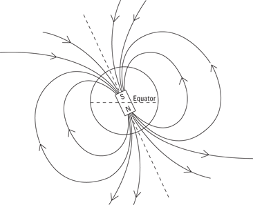
Even in bar magnets or refrigerator magnets, electricity is indeed flowing. Every atom in that refrigerator magnet has a bunch of electrons circling a nucleus, and those electrons form an electric current. This is on the level — magnetism in permanent magnets comes from those tiny orbits that electrons are continually zooming around in. Loops of current form a magnetic field, so the atoms behave like tiny magnets.
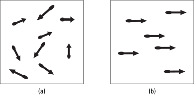
Most of the time, those tiny magnetic fields are pointing in all different directions, as you see in Figure 4-1a, so they add up to zero. However, in a permanent magnet, those tiny, atomic-level magnets are much more aligned, as in Figure 4-1b. When the micro-magnets in matter align, you end up with magnetism you can measure — and the magnet stays magnetized. That’s why you call such magnets (which take no external electrical power) permanent magnets. That alignment is the only difference between a permanent magnet and a permanent non-magnet.
Some materials are in between these opposites. For instance, all the atoms, acting like little magnets, may all start out pointing in random directions — imagine that the electrons are orbiting in planes that are randomly orientated. But when you put this material close to a magnet, the atoms are forced to rotate and align all together with the magnet. Then the magnetic influence of each atom adds together, so the material becomes magnetic. But when you take the material away from the magnet, the atoms relax back to their random orientations, and the material stops being magnetic. Such a material is called paramagnetic. Two paramagnets won’t stick to each other, but they will stick to a permanent magnet.
Figure 4-1: Micro-magnets in matter, unaligned and aligned.
In another type of material, such as iron, the atoms are organized into little aligned regions, called domains. Each domain is magnetic, but the material has many domains that are randomly orientated. Now if you place this material near a magnet, the domains are forced to align and the material becomes a magnet. But this time, when you take the material away, the domains stay aligned, and the piece of iron remains magnetic! This type of material is said to be ferromagnetic.
Electromagnets are nonpermanent magnets that work only when you have electricity flowing. I discuss these magnets later in “Going to the Source: Getting Magnetic Field from Electric Current.”
North to south: Going polar
Electricity has two sides to it: positive and negative. Electric field goes from the plus to the minus side (see Chapter 3 for details). Similarly, magnetism involves magnetic poles. And just as electric field goes from + charges to – charges, magnetic field goes from one pole to the other — from north to south.
Magnetic field is often drawn as a set of lines — that is, magnetic field lines, much as electric field is drawn as electric field lines. Figure 4-2 shows the magnetic field lines going from north pole to south of a permanent magnet.
Figure 4-2: Magnetic field from a permanent magnet.
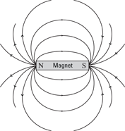
Note that the magnetic field from a magnet like the one in Figure 4-2 isn’t very constant or uniform — just like the electric field from two point charges wouldn’t be uniform.
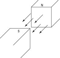
If you want a uniform magnetic field, you usually select a location between the two poles of a strong magnet, as Figure 4-3 shows. You can also create a uniform magnetic field using coils of current, as I explain later in “Adding loops together: Making uniform fields with solenoids.”
Figure 4-3: A uniform magnetic field between two poles.
Defining magnetic field
Magnetism and electricity are so interconnected that magnetic field is defined in terms of the strength of the force it exerts on a positive test charge. The symbol M was already taken (it stands for the magnetization of a material), so magnetic field ended up with the symbol B. Here’s the formal definition of magnetic field, from a physics point of view:

Here, B is the magnitude of the magnetic field and F is the magnitude of the force on the charge q, which is moving with speed v at an angle of θ to the direction of the magnetic field.
1.0 G = 1.0 × 10⁻⁴ T
Moving Along: Magnetic Forces on Charges
Electric currents and magnetic fields are linked very closely. Not only do electric currents give rise to magnetic fields, but magnetic fields also exert forces on the electric charges moving in currents.
In this section, I show you how to figure out the strength and direction of the magnetic force on a moving charge. I also explain how the direction of that force can ensure that magnetic fields don’t do any work. To finish, you see why the direction of the force causes charged particles to travel in circles in a magnetic field.
Finding the magnitude of magnetic force
To get numerical with magnetism, you have to start thinking in terms of vectors. Suppose you have an electric charge moving with a velocity v. That charge is subject to a magnetic field, B. And of course, you need the F vector for the resulting force.
How can you determine the actual force, in newtons, on a charged particle moving though a magnetic field? That force is proportional to both the magnitude of the charge and the magnitude of the magnetic field. It’s also proportional to the component of the charge’s velocity that’s perpendicular to the magnetic field. In other words, if the charge is moving along the direction of the magnetic field, parallel to it, there will be no force on that charge. If the charge is moving at right angles to the magnetic field, the force is at its highest.
F = qvB sin θ
For example, suppose you’re carrying around a 1.0-coulomb charge, and you experience a force from the Earth’s magnetic field. The Earth’s magnetic field on the surface is about 0.6 gausses, or 6.0 × 10⁻⁵ teslas. The faster you move with your charge, the more force you’ll feel, so suppose you take it for a spin in a race car. Head off down the track straight at about 224 miles per hour, or 100 meters per second. What force do you feel on your charge at this speed in the direction perpendicular to the field? You know that the magnitude of the force is given by
F = qvB sin θ
So plug in the numbers. Here’s what that looks like when you do:
F = qvB sin θ
= (1.0 C)(100 m/s)(6.0 × 10–5 T) sin 90°
= 6.0 × 10⁻³ N
The force on the charge is 6.0 × 10⁻³ newtons, which is less than the weight of a paperclip.
Finding direction with the right-hand rule
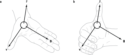
Say you have a charge, q, traveling along with velocity v, minding its own business. If that charge travels in a magnetic field, B, there’s going to be a force on the charge. You can see the direction of the magnetic force on the moving charge in Figure 4-4.
If you place the fingers of your open right hand along the magnetic field, the vector B in the figure, and your right thumb in the direction of the charge’s velocity, v, then the force on a positive charge extends out of your palm (see Figure 4-4a). For a negative charge, reverse the direction of the force.
Place the fingers of your right hand in the direction of velocity of the charge, v, and then wrap those fingers by closing your hand through the smallest possible angle (less than 180°) until your fingers are along the direction of the magnetic field, B. Your right thumb points in the direction of the force (see Figure 4-4b). For a negative charge, reverse the direction of the force.
Give the two methods a try to make sure you get the direction of the force correct.
Figure 4-4: The force on a charge on a magnetic field and the associated right-hand rules.
A lazy direction: Seeing how magnetic fields avoid work
Magnetic fields are lazy: They do no work on charged particles that travel through them — at least, not by the physics definition of work. So a charged particle in a magnetic field doesn’t gain or lose kinetic or potential energy.
When you have an electric field, the situation is very different. There, the electric field pushes a charge along or against the direction of travel. And that’s the physics definition of work:
W = Fs cos θ
where F is the force applied, s is the distance over which it’s applied, and θ is the angle between the force and the direction of travel. In fact, that’s where the whole idea of electric potential, voltage, comes from — the amount of work done on a charge divided by the size of the charge:

That’s it — the work done by a magnetic field on a moving charge is zero. That’s why there’s no such thing as magnetic potential (would that be magnetic volts?) to correspond to electric potential.
That’s all due to the physics definition of work — work changes the kinetic or potential energy of a system (or the energy is lost to heat), and nothing of the kind happens with magnetic fields. However, the direction of the charged particle does change. That’s what changes — not the particle’s speed but its direction.
Going orbital: Following charged particles in magnetic fields
The direction and magnitude of the force in a magnetic field affects the path that an electric charge takes. The direction of the force causes the charge to move in circles, and the force’s magnitude affects how big of a radius that circle has. In this section, I discuss the orbital motion of charges in magnetic fields.
Getting the curve
If you have an electric field (see Chapter 3), you know which way electric charges will move in such a field — along the electric field lines. For example, if you have a parallel plate capacitor, electrons will travel between the plates along the electric field lines, toward the positive plate. Protons will do the same, except they’ll move toward the negative plate.
The situation changes when you have a magnetic field, not an electric field. Now the force is perpendicular to the direction of travel, which can take a little getting used to. To better show the path of the charge, physicists often draw the magnetic field as though you were looking at it straight on. How can you tell which way the magnetic field is going? Here’s the physics way of showing direction:
Away from you: If you see a bunch of X’s, the magnetic field goes into the page. Those X’s are intended to be the end of vector arrows, seen tail-on (imagine looking down the end of a real arrow, tail toward you).
Toward you: Dots with circles around them are supposed to represent arrows coming at you, so in that case, the field is coming toward you.
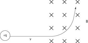
Take a look at Figure 4-5, which shows the path a positive charge moving in a magnetic field will take. The positive charge travels along a straight line, undeflected, until it enters the magnetic field that goes into the page (represented by the X’s). Then a force appears on the charge at right angles, bending its path, as you can see in the figure.
Note: This is a good place to test your understanding of the right-hand rule of magnetic force (see the earlier section “Finding direction with the right-hand rule”). Apply it to the velocity and magnetic field you see in Figure 4-5 — do you agree with the direction of the resulting force?
Figure 4-5: A positive charge being pushed in a magnetic field.
Going in circles
Here’s an interesting point: Which way do you get pushed if you’re a charged particle moving in a magnetic field? The magnetic field is always perpendicular to the direction of travel (as Figure 4-4 shows earlier in this chapter). And no matter which way the charged particle turns, the force on it is perpendicular to its motion.
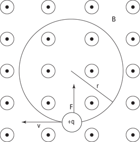
See Figure 4-6 to get the full picture. There, a positive charge is moving to the left in a magnetic field. The dots with circles around them tell you that magnetic field B is coming straight at you, out of the page. Using the right-hand rule, you can tell which way the resulting force goes — upward when the positive charge is at the location in Figure 4-6.
What happens? The charge responds to that upward force by moving upward. And because the force due to the magnetic field is always perpendicular to the direction of travel, the force changes direction, too.
Figure 4-6: In a magnetic field, a positive charge goes in circles.
Finding the radius of orbit
Suppose you want to know the radius of the orbit of the charged particle moving in a magnetic field. Because the force is always perpendicular to the direction of travel, you end up with circular motion. And from Physics I, you have the following equation for the force needed to keep an object in circular motion:

Here’s the magnitude of the force on a charged particle moving in a magnetic field:
F = qvB sin θ
Because v is perpendicular to B in this case, θ equals 90°; therefore, sin θ equals 1, which means you get this:
F = qvB
So set the two force equations — for circular motion and for the charged particle in the magnetic field — equal to each other:


That’s great — that gives you the radius of the charged particle’s path in a magnetic field, given its mass, charge, and velocity. This is one of the magnetism equations you should remember.
Magnetic field B: The stronger the magnetic field, the stronger the force — and therefore the smaller the radius of the charged particle.
Velocity v: The more speed a charged particle has, the harder it is for the magnetic field to corral the particle, and so it travels in a circle with a bigger radius.
Mass m: The more mass the charged particle has, the harder it’ll be to bend its path, so the more mass, the bigger the radius of the circle it travels in.
Notice how the equation reflects all these ideas: The magnetic field B is in the denominator of the fraction, so increasing B would give you a smaller answer for r; m and v are on top, so increasing either one of those would give you a larger r.
How about seeing this in action? Try some numbers. Say, for example, that you have a bunch of electrons going at 1.0 × 10⁶ meters per second. You don’t want to disturb the neighbors, so you decide to build a magnetic containment vessel to contain the electrons, sending them around in a circular orbit. Checking your bank account, you see you have only enough money to create a magnetic confinement vessel of r = 1.0 centimeters (even that may make your landlady suspicious, but she’s learned that physicists sometimes need unusual equipment).
So what magnetic field do you need to limit your electrons to an orbit where r = 1.0 centimeters? You know that

An electron has a mass of 9.11 × 10⁻³¹ kilograms and a charge of 1.6 × 10⁻¹⁹ coulombs. Plugging in the numbers for electrons moving at 1.0 × 10⁶ meters per second, you get

Rearranging this equation and solving for B gives you the answer:

That’s a very modest magnetic field — it’s not much more than the Earth’s magnetic field. It really doesn’t take much to push an electron around. (That’s a relief, because if you’d needed a magnetic field of several teslas, the landlady’s silverware, which is silver-plated steel, might’ve ended up stuck to her ceiling.)

doesn’t apply if the charged particle is traveling near the speed of light, v ≈ 3.0 × 10⁸ meters per second, because relativistic effects take over, which affect the mass and orbital radius of the charged particle. I discuss special relativity in Chapter 12.

Down to the Wire: Magnetic Forces on Electrical Currents
You may be one of those rare physicists who doesn’t have a bunch of electrons hurtling around at home at 1.0 × 10⁶ meters per second. You may think that the preceding discussion, about charged particles in magnetic fields, doesn’t really apply to you. However, you surely have electric cables around the house — and what are electric cables but wires through which charges move? In this section, you look at the forces that magnetic fields exert on charges moving in electric wires.
From speed to current: Getting current in the magnetic-force formula
To find the magnetic force on an electric wire in a magnetic field, you can start with the formula for individual charges. Take a look at the equation for the force on a moving electric charge in a magnetic field:
F = qvB sin θ
You want to translate this equation so that instead of using the speed of charged particles, v, it uses electrical current, I. How do you get electrical current out of this? Current is charge, q, divided by the amount of time, t, that a charge takes to pass a particular point:

Divide the equation for force by time and multiply it by time, which doesn’t actually change the equation. Here’s what you get:

Note that you now have q/t, or current, here. So here’s the force equation in terms of current:
F = I(vt)B sin θ
Okay, so what’s I(vt)B sin θ? Something of a mixed bag here — current and speed together. But if you think about it, the term vt is just the speed of the charged particles making up the current multiplied by the measured time — and speed times time equals a distance. So replace vt with L, the distance the charged particles go in time t.
F = ILB sin θ
Cool. How about an example? Look at Figure 4-7, which shows an electric current I in a magnetic field B. In physics, current goes in the direction a stream of positive charges would take (that convention was defined before scientists knew that it was negative charges — electrons — that really flowed to make current go). That means you can apply the right-hand rule to the situation you see in Figure 4-7 — just treat the direction of I as the direction a positive charge is traveling in. (For the right-hand rule, see the earlier section “Finding direction with the right-hand rule.”)
All right, what if the current, I, equals 1.0 amp, and the magnetic field, B, is equal to 5 teslas? The magnetic force on a wire carrying this current increases in proportion to its length. For every meter of wire that you have, what would be the resulting force? You start with the formula for force:
F = ILB sin θ
and then divide by the length, L, to find the force per meter:
Force/meter = IB sin θ
Figure 4-7: The force on a current in a magnetic field and the associated right-hand rule.
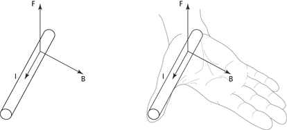
In Figure 4-7, θ is 90°, and because sin 90° equals 1, you get this case:
Force/meter = IB
= (1.0 A)(5.0 T) = 5.0 N/m
So you get a result of 5.0 newtons per meter, which works out to be about a third of a pound per foot — something to keep in mind if you have electric cables running through a 5.0-tesla magnetic field (which, admittedly, is pretty rare).
Torque: Giving current a twist in electric motors
Scientists saw that magnetic fields exerted forces on electric wires and came up with electric motors. From there came electric washers and dryers, windshield wipers on cars, elevators, automatic doors at grocery stores, refrigerators, and much more (not in that order, of course). As you can see, life without electric motors would be inconvenient. This section helps you see what makes electric motors work, electricity and magnetism-wise — at least in basic terms.

Seeing how motors work
Figure 4-8 shows an electric motor, stripped down to its basic components. Two permanent magnets of opposite polarity are on either side of the motor. This generates a uniform magnetic field in the space between the poles, from the north pole to the south pole. In this magnetic field, you place a loop of wire, which is free to rotate about the axis in the figure. A battery is connected to the loop, so a current is flowing through the wire in the direction shown by the arrows labeled I.
The wire loop is connected to the battery by a strange connection called a commutator. This clever little device is a vital part of the motor because it ensures that the current always flows in the direction shown in the diagram, even when the loop has rotated half a turn. It always connects the side of the loop that’s closest to the north pole of the magnet to the positive terminal of the battery and vice versa, while leaving the loop free to turn.
Figure 4-8: Forces, current, and magnetic field in an electric motor.
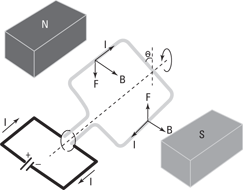
Because the loop is carrying current, the loop experiences a force in the magnetic field. I’ve shaped the loop as a rectangle to make the calculation of the force it experiences a little easier.
Two sides of the loop are parallel to the axis of rotation, and two are perpendicular to it. The perpendicular wires don’t play a part here because the force they experience is directed along the axis of rotation, so they don’t produce any torque. Also, they’re equal and opposite in size, so you don’t get a net force from them.
Most interesting are the two parts of the loop that run parallel to the axis of rotation, which are always at 90° to the magnetic field. The left side of the wire loop is forced down, and the right side is forced up (you can use the right-hand rule to confirm that the directions of the forces in Figure 4-8 are correct). This results in a turning force — that is, a torque — that rotates the loop of wire. If you connect the loop to an axle, then the loop will force the axle to turn — and you can use this turning force for all sorts of things.
Figuring out the turning force
So how much turning force does an electric motor give you? Torque, as you may recall from Physics I, is a twisting force, with the symbol τ. Here’s the formula for it:
τ = Fr sin θ
where F is the applied force, r is the distance the force acts from the turning point, or pivot, and θ is the angle between F and r.
In an electric motor, a loop of current is embedded in a magnetic field, B, and that field creates forces, F, on each wire running parallel to the axis of rotation (as you see in Figure 4-8). The torque on each wire is the force (F = ILB), multiplied by the distance, d, the force acts from the pivot multiplied by the sine of the angle. Because there are two torques, corresponding to the two sides of the loop, the total torque, τ, is equal to the following:

The product dL is the height multiplied by the width of the loop of wire — that is, the area of the loop. So if you write the area as A, the equation for the torque on a loop of wire becomes
τ = IAB sin θ
τ = NIAB sin θ
That’s the total torque on a coil of N loops of wire, each carrying current I, of cross-sectional area A, in a magnetic field B, at angle θ as shown in Figure 4-8.
In physics class, you’re usually asked what the maximum torque would be for such-and-such a coil in such-and-such a magnetic field. If you come across a situation like that and need to find the maximum torque, that occurs when the coil is at right angles to the magnetic field: θ = 90°, so sin θ = 1, or
τ = NIAB
Try some numbers here. If you have a coil with 200 turns, a current of 3.0 amps, an area of 1.0 square meters, and a magnetic field of 10.0 teslas, what’s the maximum possible torque? Just plug this into the equation:
τ = NIAB = (200)(3.0 A)(1.0 m2)(10.0 T) = 6.0 × 10³ N-m
So you have a maximum torque of 6,000 newton-meters, which is very large — a car typically generates only about 150 newton-meters.
Going to the Source: Getting Magnetic Field from Electric Current
The earlier sections in this chapter concentrate on how magnetic fields exert forces on moving charges, or currents, without worrying too much about where the magnetic field came from in the first place. In this section, you discover the source of that magnetic field. Here, you see the relationship between electricity and magnetism become complete.
In Chapter 3, I take a couple of simple arrangements of charge (the point charge and the parallel plate capacitor) and examine the resulting electric fields. Now, in this section, I take a few simple arrangements of current (a straight wire, a loop, and a tube of current called a solenoid) and examine the resulting magnetic fields. Here, you also see how you can use this idea to make electromagnets, magnets that you can switch on and off with a switch.
Producing a magnetic field with a straight wire
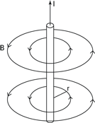
To understand how electric current produces a magnetic field, first take a look at the magnetic field from a single wire, as Figure 4-9 shows. Why start here? When you know what the magnetic field is from a single wire of current, you’re home free in many problems. You can often break down more-complex distributions of current into many single wires — and then add the magnetic fields from the wires as vectors to get the overall result.
Figure 4-9: The magnetic field from a single wire of current.
Assembling the formula for magnetic field from a single wire
When you make physical measurements of the magnetic field from a single wire, you find that the magnetic field, B, diminishes as 1 over the distance, r. Therefore, you get this relation (where ∝ means proportional to):

What else can the magnetic field depend on? Well, how about the current itself, I? Surely if you double the current, you get twice the magnetic field, right? Yep, that’s the way it works, as borne out by measurement, so now you have the following:

That’s all you need.

Note that the constant μo = 4π × 10–7 T-m/A.
A right-hand rule: Finding field direction from a wire
Figure 4-10: A right-hand rule shows the direction of current in a wire and the resulting magnetic field.
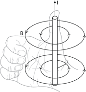
Give this a try: Suppose you have two parallel wires. Verify that the force between two wires is toward each other if the current in both is in the same direction and away from each other if the current in each wire is in opposite directions.
Calculating magnetic field from straight wires
How about some numbers? Say you have a current of some 10 amps and you want to measure the magnetic field 2.0 centimeters from the center of the wire. What is the strength of the B field you’ll get? Here’s your formula:

Plugging in the numbers gives you:

So you get 1.0 gausses, a little more than the Earth’s magnetic field, which is about 0.6 gausses.
That was a quick example — how about one that’s a little tougher? Say you have two wires, parallel to each other, with current I in each going the same way. The wires are a distance r apart. What’s the force on Wire 1 from the magnetic field coming from Wire 2?
You know that the force on Wire 1, which is carrying current I in magnetic field B, is the following (to see where this formula comes from, check out the earlier section “From speed to current: Getting current in the magnetic-force formula”):
F = ILB
All right, but what’s B? That’s the magnetic field from Wire 2, measured at the position of Wire 1. Because the wires are r distance apart and Wire 2 is carrying a current I, its magnetic field is this at the location of Wire 1:

Substituting this expression for B into the F = ILB equation, you get this result:

How about getting the force per unit length? That’s F/L, which is

Now try some numbers. Say you have two parallel wires with current I going in the same direction — current, I, is 10 amps, and the distance between the wires, r, is 2.0 centimeters. Putting in those numbers, you get

So the force on Wire 1 from Wire 2 is 1.0 × 10⁻³ newtons per meter. Note that the force on Wire 2 from Wire 1 is the same magnitude.
Getting centered: Finding magnetic field from current loops
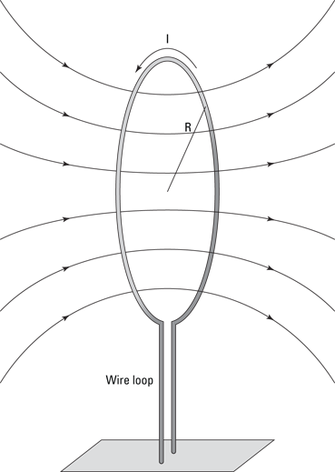
Suppose you have a loop of current, such as you see in Figure 4-11. The magnetic field from a single loop of wire (even if it has many turns) is not constant over the various points in space.
That variation in the magnetic field is a bit of a problem, because the actual equation for the magnetic field from a loop of current is very complicated. So physicists do what they always like to do — they simplify. Here, simplifying takes the form of measuring the magnetic field at the very center of the loop. (In the next section, you see that putting multiple loops together to form a tube of current also smoothes out the magnetic field.)
Here, start by noting that the magnetic field at the center of a loop of current is equal to the following:

where N is the number of turns in the loop, I is the current in the loop, and R is the radius of the loop.
Figure 4-11: The magnetic field from a current loop.
Try some numbers. Say that you have a loop of 200 turns of wire and a radius of 10 centimeters. What current would you need to get the equivalent of the Earth’s magnetic field, 0.6 gausses, in the center?
Plug in the numbers, making sure you first convert from gausses to teslas (1.0 G = 1.0 × 10⁻⁴ T) and from centimeters to meters. Here’s what you get:

Solve for I to find the answer:

You’d need 4.8 × 10⁻² amps in this current loop to mimic the Earth’s magnetic field.
Armed with this knowledge, you can understand how an electromagnet works. An electromagnet is simply made of a loop of wire with many turns, usually wound around a piece of iron to concentrate the field. When the current flows, this device produces a magnetic field. So you don’t have to dig in the Earth to find magnetic rocks anymore — you can make a magnet that works at the flick of a switch.
Adding loops together: Making uniform fields with solenoids
One of the major problems with loops of current is that the magnetic field isn’t constant over various points in space, which is why physicists talk in terms of the magnetic field at the center of a loop.
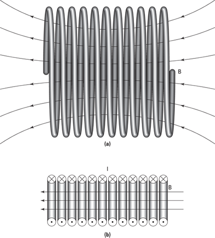
To get around that problem, you can assemble many loops of current next to each other, just a little distance apart, to create a solenoid. This gives you a uniform magnetic field — just as parallel plate capacitors give you a uniform electric field (see Chapter 3 for info on parallel plate capacitors). How does the magnetic field become constant inside a solenoid? When you put multiple loops next to each other, as in Figure 4-12a, the edge effects of the loops cancel, and you get a uniform magnetic field, as in Figure 4-12b.
What is the magnitude of a solenoid’s magnetic field? If the length of the solenoid is large compared to its radius, you get this equation for the magnetic field:
B = μonI
where n is the number of wire loops in the solenoid per meter — that is, the number of turns per meter — and I is the current in each turn.
How about the direction of the magnetic field? That’s easy enough: You can use the right-hand rule for current loops (see the preceding section) to figure out which direction the magnetic field goes in for a solenoid. Just take a look at Figure 4-12 to confirm you’re getting it right.
Figure 4-12: A solenoid produces a uniform magnetic field.
Here’s an example. Say that you’re conducting some crucial lab experiments and need a 1.395-tesla magnetic field. How much current would you need to run through a solenoid of some 3,000 loops, 1.00 centimeters in length, to get that magnetic field?
Start by solving for the current, I:

Then just plug in the numbers; note that because you have 3,000 1-centimeter loops, you use 300,000 — or 3.0 × 10⁵ loops per meter — as your value for n:

In other words, you need about 3.70 amps, which isn’t too much.

