Chapter 9
Bending and Focusing Light: Refraction and Lenses
In This Chapter
Bending light as it enters new materials
Refracting light enough to get internal reflection
Drawing ray diagrams for converging and diverging lenses
Using equations relating distances and magnification
Using lenses in combination
Here’s a cool quality of light: It interacts with matter so that it bends. Instead of just passing through the universe oblivious to everything else, light is affected by the matter through which is passes, whether that matter is dense like a diamond or thin as air.
Why does light bend? It bends because light is made up of electromagnetic waves — that is, tiny electric and magnetic fields — and they actually interact with the tiny electric and magnetic fields you find in matter (coming from charged particles, such as electrons and protons, and their motion).
This chapter first introduces a different way of representing light waves: the ray. Then it begins a discussion of the tricks that light can play as it bends in glass, water, and other such media. You start by getting a handle on the index of refraction, which is all about just how much light bends in any given material. You also see lenses bring images into focus, or even total internal reflection when light can’t make it out of a block of glass like a prism.
Wave Hello to Rays: Drawing Light Waves More Simply
When you’re exploring the various paths that light waves take as they bounce off and bend through various reflective or transparent materials, you’re more interested in the places that the waves go, their directions and deflections, than the details of the wave fluctuations of electric and magnetic fields. So for simplicity, you can forget about electric and magnetic fields in most of this chapter and deal with rays of light (I point out when you need to take note of light’s wavy nature). A ray just tells you the wave’s direction of travel without showing the wavelength or speed or frequency or the positions of the wave peaks — the kinds of things I cover in Chapter 8.
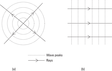
Rays are not a new thing — you probably already think of light as rays anyway. They’re just a simpler way to refer to the light wave. You can see what I mean by rays in terms of the light-wave picture in Figure 9-1. Here’s how to interpret this figure:
The dotted lines represent the light waves by showing the positions of the wave peaks of the electric field.
Solid lines are some of the rays that represent the same wave. You can see that these are just lines that are always at right angles to the wave peaks — so they always lie in the direction of travel of the waves. The arrows on the rays show this direction.
In Figure 9-1a, the light waves come from a single point (that is, you have a point source), and they’re spreading out in all directions. Because this light is traveling in all directions from the central point, any line drawn radially outward from this point is a ray.
Figure 9-1b shows another example of rays representing waves. This time you have a plane light ray traveling to the right. I’ve drawn three of the rays that represent this wave.
Figure 9-1: Rays and waves.
![]() When working with light rays, just remember two basic principles:
When working with light rays, just remember two basic principles:
Rays travel in straight lines. When they meet a surface, they may reflect or deflect, but while they’re traveling through the same medium without boundaries, rays travel in straight lines.
Rays are reversible. When a light ray travels between two points (say, A to B) along a path, then the light from B to A follows the same path in the opposite direction.
Slowing Light Down: The Index of Refraction
As soon as you get past the concept that light consists of alternating E and B fields that regenerate each other, that there’s a maximum speed at which light can travel (which you can calculate theoretically), and a few other items (see Chapter 8), light traveling in a straight line through a vacuum forever isn’t all that interesting. Sure, you could spend some time studying the situation, but when you have it pretty well scoped out, you kind of wish something else would happen.
But when light hits and starts traveling through something else, then light becomes interesting again. When light in a vacuum enters any material and begins to travel through that material instead, the light slows down, because the electric and magnetic fields around the light in the material act as a drag. For example, when light impacts a block of transparent material (this is all theoretical, so make it a 60-pound block of diamond), the light slows down and bends.
In this section, you look at how much that material slows light down and see how much the light bends as a result. I also show you that not all light bends equally, because the index of refraction varies depending on the wavelength of the light.
Figuring out the slowdown
Light reaches its maximum speed, c, in a vacuum. That’s about 3.0 × 10⁸ meters per second, and it’s all downhill from there, because whenever light travels through anything else — even air — it slows down.
 The ratio of the speed of light in a vacuum, c, to the speed of light in a material, v, is a constant for any given material, and that ratio is called the index of refraction, n. Here’s the definition of the index of refraction:
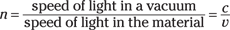
The index of refraction is just a pure number, because it’s the ratio of speeds, so it has no units, like relatively few other quantities in physics.
 Generally speaking, the denser the material, the more electric and magnetic fields it has to slow light down. So diamond, for example, has a higher index of refraction than air. Table 9-1 gives a starter list of indexes of refraction for various materials. The table also includes temperature, which can affect the density of the material and therefore its index of refraction.
 A material usually contracts as its temperatures decreases, so it becomes denser and its index of refraction can rise. However, water is a special case. Ice (at 0°C) has a refractive index of 1.32, and water has the higher value of 1.33. When the water freezes, the molecules form ice crystals, which happen to have a structure that’s less dense than the original water. That’s why ice floats on water.
|
Table 9-1 Indexes of Refraction for Various Materials |
||
|
Material |
Temperature (°C) |
Index of Refraction (n) |
|
Diamond |
20°C |
2.42 |
|
Window glass |
20°C |
1.52 |
|
Benzene (liquid) |
20°C |
1.50 |
|
Water |
20°C |
1.33 |
|
Ice |
0°C |
1.32 |
|
Air |
20°C |
1.00029 |
|
Oxygen |
20°C |
1.00027 |
|
Hydrogen |
20°C |
1.00014 |
So if diamond has a refractive index of 2.42 at 20°C, what’s the speed of light in a diamond? Well, it’s
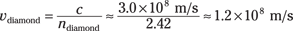
So light travels at only 1.2 × 10⁸ meters per second in diamond. Positively pokey.
Calculating the bending: Snell’s law
When light slows, it bends. You can put the index of refraction to work with Snell’s law, which tells you exactly how much light bends when it enters a new medium. (See the preceding section for info on the index of refraction.)
The incident (incoming) light comes in at an angle of θ1, measured with respect to a line perpendicular to the material’s surface — that perpendicular line is called a normal (see Figure 9-2). And when the light bends and travels off into the medium, it goes at a new angle with respect to the normal, θ2. Here’s how the angles relate:
n1 sin θ1 = n2 sin θ2
where n1 is the index of refraction of the medium the light is coming from (it doesn’t need to be vacuum to have Snell’s law work) and n2 is the index of refraction of the medium the light enters (which could be diamond, or glass, or even vacuum).
Note that if you know the incident angle and the indexes of refraction of the materials involved, you can solve for the angle at which light heads off into the new medium like this:
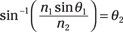
That’s a nice result — it tells you what angle you can expect light to go speeding off at in a new medium.
Figure 9-2: Snell’s law.
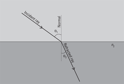
Here’s one thing that Snell’s law tells you that’s not immediately obvious: If you’re going from less-dense to denser material, light is bent toward the normal; if you’re going from denser to less-dense material, light is bent away from the normal.
For instance, if you look at Figure 9-2, you see the light ray traveling from less-dense to denser material, and the light bends toward the normal. Now if you remember that light rays are reversible, you can imagine the same ray going in the opposite direction (from the denser to the less-dense material) — then the ray bends away from the normal.
Now try some numbers. Say that light goes from air (which you can treat as vacuum for the purposes of this example) to your 60-pound diamond block. And say that light hits the diamond at 65° with respect to the normal. What’s the angle the light bends to inside the diamond?
That is, you have n1 = 1.00, n2 = 2.42, and θ1 = 65°, and you need to find θ2. You can use Snell’s law like this:
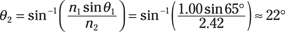
So the light comes in at 65° and ends up at 22°.
Rainbows: Separating wavelengths
Here’s something that you may not like to hear because it complicates things a bit: The index of refraction of materials varies slightly depending on the wavelength of the light. On the other hand, you probably like the results of this fact: rainbows. Because the colors in sunlight (which contains all colors) bend different amounts in water droplets, you get a separation of colors into that familiar display of rainbows.
The index of refraction does vary by light wavelength but not strongly (so physicists often ignore it). Table 9-2 lists some values for the various colors of light and what the corresponding indexes of refraction are in glass.
|
Table 9-2 Indexes of Refraction According to Wavelength |
||
|
Color |
Wavelength (nanometers) |
Index of Refraction in Glass |
|
Red |
660 |
1.520 |
|
Orange |
610 |
1.522 |
|
Yellow |
580 |
1.523 |
|
Green |
550 |
1.526 |
|
Blue |
470 |
1.531 |
|
Violet |
410 |
1.536 |
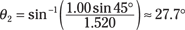
Say that light is incident at 45° to a sheet of glass. How much does red light (λ = 660 nm) bend, compared to violet light (λ = 410 nm)?
Snell’s law tells you that n1 sin θ1 = n2 sin θ2, so

The light is first traveling through the air, so n1 = 1.00. For red light in glass, the index of refraction is 1.520, so you get
For violet light, the index of refraction in glass is 1.536, so you get
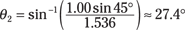
So as you can see, you get different amounts of bending depending on the color of light. Note that the angle calculated is with respect to the normal, so violet light is bent slightly more than red light here.
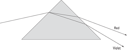
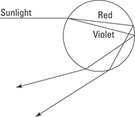
Because of the differing indexes of refraction for different wavelengths, light splits in a prism (see Figure 9-3). Here’s how it works: when light enters the prism, it’s going from air into a medium with a higher index of refraction — typically glass — so it bends in the glass toward the normal (a line perpendicular to the surface). Because the index of refraction is stronger for shorter wavelengths, red light (with a longer wavelength) bends less than violet light (with a shorter wavelength). When the light emerges from the prism, it bends away from the normal, and how much it bends depends on the index of refraction — so red light is further separated from violet light.
In actual rainbows, the light not only refracts when it enters the water droplet but also reflects inside the water droplet. You can read more about this phenomenon in the sidebar “Reflecting on rainbows,” later in this chapter.
Figure 9-3: A prism separates colors because shorter wavelengths bend more.
Bending Light to Get Internal Reflection
When light enters a material with a lower index of refraction, that light bends away from the normal (an imaginary line perpendicular to the material’s surface). If the incident light comes in at a large enough angle, the light may bend away so much that it doesn’t refract at all — it gets reflected instead.
In this section, I discuss two cases in which you get reflection. In the first, all the incident light is reflected. In the second, only polarized light — light with aligned electric and magnetic fields — is reflected, and the rest of the light is refracted as it enters the less-dense material.
Right back at you: Total internal reflection
Sometimes light doesn’t make it out of a material, and it ends up bouncing around inside. Perhaps you’ve noticed that when you turn a glass paperweight, one of the internal edges sometimes looks like a mirror, reflecting with a silvery appearance. That’s total internal reflection.
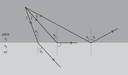
To see how this works, take a look at Figure 9-4. Light is going from a dense medium such as glass to air. That means that the light bends away from the normal when it gets into the air, as you see in ray 1. If you keep increasing θ1, ultimately, θ2 reaches 90° — that is, the light just skims along the glass surface, as in ray 2. If you increase θ1 any more, the light will be reflected back into the glass, as you see in ray 3. This is what’s known as total internal reflection. When light goes from a dense medium to a less-dense medium, it bends away from the normal, and if the incident angle becomes large enough, the light will be reflected back into the denser medium where the two materials meet.
Figure 9-4: Total internal reflection.
Total internal reflection happens when the angle at which the light tries to exit the dense medium, θ2, becomes so large that it reaches 90°. Right at that point, when the light ends up skimming the glass/air interface, you have total internal reflection. The incident angle at which this happens is called the critical angle — θc. At the critical angle, light ends up with an exit angle of 90° with respect to the normal. In other words, when θ1 = θc, θ2 = 90°.
What value does θc have? You can use Snell’s law to find out:
n1 sin θ1 = n2 sin θ2
Plugging in the values, you get
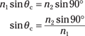
Because sin 90° = 1, you have the following for the critical angle for total internal reflection:
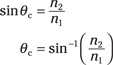
Note that this equation requires that n2 < n1 (otherwise you can’t have total internal reflection).
Reflecting on rainbows
Rainbows form when water droplets are in the air. Creating rainbows is a matter of varying indexes of refraction. Red light, for instance, bends less when it enters the water droplet, and violet light bends more.
Specifically, sunlight enters the droplet, and all the colors of the rainbow begin to separate immediately. In this case, violet bends more than red. Then, given the angle of incidence when the split light tries to leave the droplet, total internal reflection occurs. The light ends up leaving the front of the droplet — and violet is bent more than red again, as this figure shows. The result — all the colors of the rainbow. Physics does it again!
For example, say you have a diamond ring and that light is bouncing around inside the gem. What’s the critical angle beyond which light already inside the diamond gets totally internally reflected back into the diamond? You can use the equation for total internal reflection. The index of refraction of air is near 1.00, and the index of refraction for diamonds is 2.42, so you have the following:
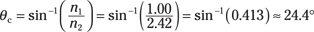
So if light hits the diamond-air interface at an angle of more than 24.4°, it’ll bounce back into the diamond, and that facet of the diamond acts like a mirror — that’s one of the reasons properly cut diamonds seem to exhibit so much fire.
Polarized light: Getting a partial reflection
Here’s a peculiar fact about light — when it bounces off a nonmetallic surface, it gets polarized. That means that the light rays’ electric fields are lined up and its magnetic fields are lined up.
When you talk about polarization, you normally discuss the direction of the electric (E) field in the light ray. The E field oscillates in a direction that’s perpendicular to the light ray’s direction of travel, and the plane that the light ray and the E vector form is called its polarization. So if you have a light ray coming toward you and its E vector is oscillating horizontally, the light is polarized horizontally.
With normal light, the E vector can oscillate in any direction perpendicular to the direction of travel. But when you bounce light off a nonmetallic surface, the reflected light ends up being polarized to some extent in the plane of the surface. For example, if light bounces off a pool of water, the reflected light ends up being chiefly polarized in the horizontal direction.
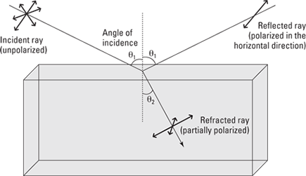
In Figure 9-5, you see the incident ray coming in from the left. A number of arrows in all directions (perpendicular to the direction of travel, of course) represent the unpolarized electric-field component of this ray. The reflected ray on the right is totally polarized, so it has electric field oscillations only in the horizontal direction. The refracted ray is partially polarized, because the reflected wave preferentially carried away electric field oscillations in the horizontal direction, leaving the refracted wave with relatively few. You can see this in Figure 9-5 — in the refracted ray, the arrows representing the horizontal electric field oscillations are diminished compared to the others.
Figure 9-5: The light reflecting off the surface is polarized.
Reflecting polarized light at Brewster’s angle
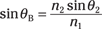
When light bounces off a nonmetallic surface, the amount of polarization depends on the angle of incidence (with respect to the normal, an imaginary line perpendicular to the surface). And at an angle of incidence called Brewster’s angle, θB, the polarization is total. So when light reflects off a pool of water at Brewster’s angle, the reflected light is completely polarized in the horizontal direction. Here’s the formula for Brewster’s angle:

where n1 and n2 are the indexes of refraction. So what is Brewster’s angle for water? Well, the index of refraction for water is about 1.33 and the index of refraction for air is about 1.00, so you have the following:
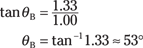
So Brewster’s angle for water is 53°.
Noting the angle between the reflected and the refracted rays
You can prove that the refracted ray, which enters the water, is at 90° with respect to the reflected ray if the incident light enters the water at Brewster’s angle (the angle at which polarization is total). To prove this, start with Snell’s law:
n1 sin θ1 = n2 sin θ2
where θ1 and θ2 are shown in Figure 9-5. You can write this as the following, using Brewster’s angle, θB, for θ1:
Using Brewster’s equation, you know that

You have tan θB = sin θB/cos θB, which follows from the trig definition of the tangent, so do the following calculations:
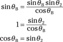
And because sin θ = cos(90° – θ), you can say that
cos θB = cos(90° – θ2)
θB = 90° – θ2
So Brewster’s angle is 90° from the refracted angle. Cool.
Getting Visual: Creating Images with Lenses
Many weird and wonderful things happen to light when it hits curved surfaces, so in this section, you step into a world of images. You find out what the field of optics considers to be an object and how images are made by the curved surfaces of lenses. This is the physics that led to telescopes and microscopes, which opened up new doors of perception of the universe.
Here, I demonstrate how you work out where and how big an image will be simply by drawing a few lines. Such ray drawings can give you a good mental picture of what lenses do to the light that passes through them. After this, I show you a couple of equations, which tell you exactly where the images are and how big they are, without your having to take out your ruler and pencil.
Defining objects and images
As far as the field of optics is concerned, an object is simply a source of light rays. It doesn’t have to glow with light; it can just reflect light from another source. The important point is that light rays should radiate away from the object. For example, this book would be considered an object in physics. The book isn’t generating the light, only reflecting it from your lamp or the sun or whatever the light source is where you’re reading.
For simplicity, this book considers only very simple objects like point sources, which are simply points that radiate rays, or line sources. A line source is simply a line that radiates rays in all directions from every part of it — physicists draw these as arrows, because sometimes you find them upside down, and the arrowhead emphasizes direction.
So much for objects — now what about the images that are made from them? Well, the simplest example of an image is one you probably see every day — your own image in the mirror. In this case, you’re the object (no offense!), and the mirror reflects the rays coming from you and makes an image behind the mirror. The image is the point from which the rays leaving your face seem to be coming from. You know that you — the object — are not behind the mirror, but your image appears behind. This kind of image is called a virtual image.
Another example of an image is the one projected in a cinema. Each frame of the movie is turned into an image, which is projected onto the screen. This is a different type of image from the one you see in the mirror, because the rays don’t just appear to be coming from the image — they actually converge onto the image. That is, the rays make the picture all come together on the movie screen. Because this type of image can be made to fall on a screen, it’s called a real image.
Now it’s coming into focus: Concave and convex lenses
You can find lenses everywhere — in standard digital cameras, in TV cameras, perched on the end of peoples’ noses, in flashlights, even sometimes in peoples’ watches when the really tiny date has to be magnified. A lens is simply a transparent object (usually a disk of glass), that takes an object and makes an image. It can do this because it has two curved surfaces.
Here are two types of lenses:
Convex (converging): A convex lens curves so that it bulges in the middle (see Figure 9-6). When you put a point object in front of this lens, some of the rays that radiate away travel through the lens. When they meet the first surface, they refract, or bend, and when they leave the lens, they refract some more. The effect of the convex lens in Figure 9-6a is to gather all these rays together back to a point — this is your image. Because all the rays converge there, it’s a real image.
If a number of parallel rays strike the lens, then they all converge on a point called the focal point, as you see in Figure 9-6b. You may have already discovered the focal point for yourself if you’ve ever tried to focus sunlight into a single bright spot with a magnifying glass. The sun is so far away that the rays coming from it are pretty much parallel, so when they pass through your magnifying glass, they converge at the focal point. If you place a piece of paper there, then all the converging rays can make the paper burn.
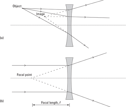
Concave (diverging): A concave lens is narrower in the middle. This time, when the rays from the object strike the lens, they diverge. All the rays appear to diverge from a certain point, and this is the virtual image. See Figure 9-7a.
Now if you send a bunch of parallel rays into a concave lens, they all diverge, but they all appear to be diverging from the focal point (see Figure 9-7b).
The way I remember the difference between convex lenses and concave lenses is that a diverging lens forms a sort of a cave (because its middle is all hollowed out), as in concave.
The distance between the lens and the focal point is called the focal length, f. The strength of a lens is measured solely by this length — if it’s shorter, then the rays are bent through a larger angle, and the lens is stronger.
In many lenses, one of the lens’s surfaces may curve more than the other. Even in those cases, there’s still only one focal length, so the focal point on each side of the lens is at the same distance, f. Also, however the sides are curved, if the lens is thicker in the middle than at the edges, it’s convex; otherwise, it’s concave.
Figure 9-6: Light passing through a convex lens.
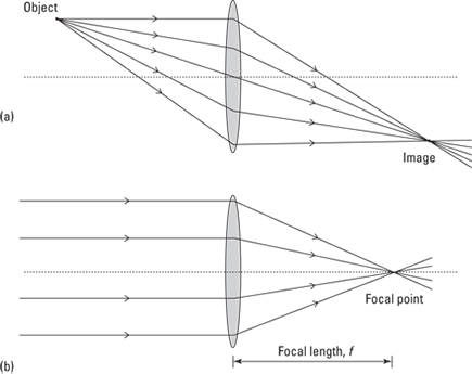
Figure 9-7: Light passing through a concave lens.
Another special point for a lens is the center of curvature, which is a distance, C, from the lens. The distance between this point and the lens is called the radius of curvature.
The radius of curvature is not related in a simple way to the amount of curvature of the lenses; instead, just think of it in terms of the focal length of the lens. The radius of curvature is simply twice the focal length, C = 2f.
The dotted line in Figures 9-6 and 9-7 is called the optical axis of the lens. It’s just the line that passes through the lens at its widest part (or thinnest part if the lens is concave) and that’s normal (perpendicular) to the surface of the lens there.
Drawing ray diagrams
You can draw three special lines to find the image that a lens makes, based on where the object is. These lines tell you where the image appears, whether it’s upside down or right-side-up, whether it’s larger or smaller than the original object, and whether the image is real (made of converging light rays) or virtual. In this section, you discover how to draw ray diagrams for both convex (converging) and concave (diverging) lenses.
The object I use in each section is a line object, which looks like an arrow. The arrowhead makes sure you always know whether the image is upside down or the right way up. You can think of this type of object as just being a lot of point objects all in a line. (For more on objects and point and line sources, see the earlier section “Defining objects and images.”)
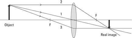
X marks the spot: Finding images from convex lenses
The position and size of the image depend on the position and size of the object. For a convex (converging) lens, here’s how to draw three special lines that help you figure out the position and size of the image (see Figure 9-8):
Ray 1: One ray leaves the object, travels toward the center of the lens, and travels straight through without being deflected at all.
Ray 2: Another ray travels from the object, parallel to the axis of the lens, and is deflected so that it passes through the lens’s focal point.
Ray 3: A third ray travels from the object and passes through the focal point on the near side before reaching the lens. The lens deflects this ray so that it then travels parallel to the axis of the lens.
The image is located where these three lines cross.
You can draw these ray lines for any point on your object and find every point of the image, but for simplicity, most people draw only the lines from the tip of the object (the point of the arrow). And although I draw three rays in Figure 9-8, you really need only two rays to locate the image. Three is better for safety — as a check on the other two — but if you know what you’re doing and are under time pressure (such as when you’re taking a test), two is enough.
Figure 9-8: Drawing three special rays for a convex lens.
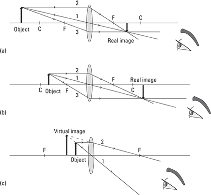
If you go through the line-drawing process for convex lenses, you encounter three special cases for what the image looks like. Here are these cases, which are all based on the position of the object (if you need more info on the focus and radius of curvature, see the earlier section “Now it’s coming into focus: Concave and convex lenses”):
The object is beyond the radius of curvature, C: If the object is this far out, the image is real, upside down, and smaller than the object (see Figure 9-9a).
The object is between the radius of curvature, C, and the focal length, f: Here the image is still real and upside down, but now it’s larger than the object (see Figure 9-9b).
When the object is at the center of curvature, then its image is the same size as the object, and the closer the object gets to the focal point without crossing, the larger the image becomes.
The object is closer to the lens than the focal length, f: This is an interesting case, because for the first time, you don’t get a real image (see Figure 9-9c). You can’t even draw the third ray, because it doesn’t go through the lens. There’s no place in space that the three rays come together, no place that you can bring an actual physical screen and get an in-focus image — the image is virtual. It’s also larger than the object and right-side-up.
Figure 9-9: Ray diagrams for three special cases of images from a convex lens.
Recognize the situation in which the object is between the focal point and the lens? That’s the case where a converging lens forms an upright image that’s larger than the object you’re looking at, on the same side of the lens as the object itself (the image is virtual, so no light rays actually come together to form the image, but looking through the lens bends the rays so that they appear to be coming from the image). That’s a magnifying glass — and the fact that you don’t get an enlarged upright image until the object is between the focal point and the lens shows why you have to hold the lens up close to whatever you’re trying to magnify. Cool, eh? Sherlock Holmes would be proud.
Going virtual with concave lenses
With a concave (diverging) lens, light bends away from the horizontal after passing through the lens. You can see a diverging lens in Figure 9-10.
So when you have a diverging lens, can you work with ray diagrams to find the image? Absolutely — but this time you use only two rays:
Ray 1: This ray goes from the tip of the object and through the center of the lens. Figure 9-10 shows that this ray goes through the center of the lens and isn’t deflected at all. Easy.
Ray 2: This ray goes horizontally from the tip of the object to the lens, parallel to the axis of the lens; then the ray deflects away from the axis along a line that passes through the nearest focal point — that is, the ray travels as though it came from the nearest focal point. Figure 9-10 shows that the second ray bends away from the horizontal on the other side of the lens.
Figure 9-10: A concave lens produces a smaller, upright virtual image.
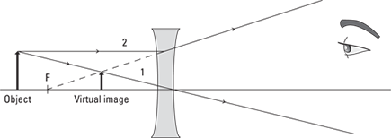
So if the second ray is bent away from the horizontal, where does it intersect the first ray? The answer is that they don’t intersect on the side of the lens that the observer (who is looking through the lens) is on. Instead, you extend the rays back through the lens until they intersect. Because you’re extending these rays in a straight line back to somewhere they don’t actually exist, the image is virtual. In other words, the image forms on the same side of the lens as the object, as you see in Figure 9-10.
Regardless of where the object is, the virtual image from a concave lens is always right-side-up, and it’s no farther from the lens than the focal length. The image is also upright and smaller than the object.
Getting Numeric: Finding Distances and Magnification
With a few lens equations, you can find out where images appear and how big they are. Drawing ray diagrams (as I show you in a preceding section) is a good way to get a strong picture of what lenses do, but when you have that in mind, you’ll find these equations a much quicker way of finding out what your lenses are doing.
There’s really nothing mystical about the equations in this section — they just come from the laws of refraction (which you can examine in “Slowing Light Down: The Index of Refraction,” earlier in this chapter). People derived these equations by applying the law of refraction to the curved surfaces of the lenses, but you don’t have to bother doing that — here, I just show you how the equations work.
Going the distance with the thin-lens equation
Using the thin-lens equation, you can relate the distance an object is from a lens, the distance from the lens to the image, and the lens’s focal length. The equation is called the thin-lens equation because it’s actually an approximation, and that approximation really holds only for “thin” lenses — that is, lenses whose bending power isn’t too great (stronger lenses have a shorter focal length, so strong lenses have to be more curved and therefore thicker). This section gives you the equation, shows you how it works, and provides a couple of example calculations.
Introducing the thin-lens equation
Here’s the thin-lens equation:

This equation relates the distance the object is from the lens (do) and the distance the image is from the lens (di) with the focal length, f.
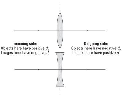
The signs of do, di, and f are important. For instance, you give converging lenses a positive focal length f, but diverging lenses get a negative focal length (that’s because the image forms on the other side of the lens from the observer). And if you get a negative distance for the image distance, di, that means the image is virtual (which, for a lens, means that the image forms on the same side as the object).
The best way to state the rules for the signs of do, di, and f in the thin-lens equation is in terms of the incoming and outgoing sides of the lens (see Figure 9-11). When light from an object travels through a lens, I call the side that the light enters the incoming side; the side of the lens through which the light leaves is the outgoing side. Then the rules are simple to state:
Object distance, do: When the object is on the incoming side of the lens, then the distance from the object to the lens is positive (in this book, this is always the case).
Image distance, di: When the image is on the outgoing side of the lens, then the image distance is positive; otherwise, it’s negative.
Focal length, f: When the lens is convex, its focal length is positive; otherwise, it’s negative.
Note: This book always pictures the object to the left of the lens, so the incoming side is on the left in the figures (including Figure 9-11). But these rules still apply in exactly the same way if this situation is reversed, because then the incoming and outgoing sides would also reverse.
Figure 9-11: Sign rules for object and image distances.
Doing calculations with the thin-lens equation
Now try some numbers with the thin-lens equation. Say that you have a camera with a converging lens that has a focal length of 5.0 centimeters, and the flower you’re taking a picture of is 2.00 meters in front of the lens. How far on the other side of the lens does the image form? You can put the thin-lens equation to work right away:

Rearranging this gives you

Combining the fractions and solving for di gives you

So plugging in the numbers gives you the following:

So the image forms at 5.1 centimeters behind the lens of the camera (on the side opposite to the flower).
Now try one with a diverging lens. Say you have a diverging lens with a focal length of –5.0 centimeters (See? I told you diverging lenses get negative focal lengths), and you place an object 7.0 cm in front of it. Where does the image appear to form?
You can use the thin-lens equation like this:

And I’ve already solved for di this way:

Plugging in the numbers gives you the answer:

So the image forms at –2.9 centimeters — that is, between the focal length and the lens. Note that this result is negative. That means that the image is visible only by looking through the lens — not on the same side of the lens as the observer. In other words, it’s a virtual image, as you’d expect from the type of lens and the placement of the object (to see why, check out the ray diagram in Figure 9-10).
Sizing up the magnification equation
The thin-lens equation tells you where an image will form, but it doesn’t tell you very much about the image itself. Sometimes, you want to know whether that image is bigger or smaller than the object and whether it’s upright or upside down with respect to the object. That’s where the magnification equation comes in.
Finding the magnification equation
Say that hi is the height of the image and ho is the height of the object. You can see that the magnification of the image compared to the object would be m, like this:

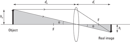
Figure 9-12 shows two of the rays that go to make the image of an object from a convex lens. The figure shows the size of the object and the image, along with the distances of the object and image from the lens. The ray that travels straight through the lens makes an angle θ with the axis. By using geometry and similar triangles (shaded gray in Figure 9-12), you can show that the magnification is equal to the ratio of the image distance to the object distance like this:

Note that a negative value for the magnifications means the image is upside down with respect to the object, and positive magnification (the kind magnifying glasses and most optical telescopes produce) means that the image is right-side-up compared to the object.
Figure 9-12: The magnification of a convex lens.
Why does the magnification equation have a minus sign in it? That’s because the magnification of a magnifying glass — that is, a converging lens — is considered positive when the image is virtual, because you look through the lens to see the image and it’s right-side-up. But because the image is virtual, the distance to the image from the lens, di, is negative. The minus sign in the magnification equation corrects that — so even though the image comes out virtual (which means negative in the thin-lens equation), it’s still upright (which by convention means positive in the magnification equation).
Plugging in some numbers
Now you can figure out the distance from a lens to an image using the thin-lens equation, and because you already know the distance from the object to the lens, you can use the magnification equation to figure out the magnification.
Try some numbers. Start by taking a look at the converging-lens problem from the earlier section “Going the distance with the thin-lens equation”: The camera has a converging lens that has a focal length of 5.0 centimeters, and the object you’re taking a picture of is 2.0 meters in front of the lens. In this problem, the distance from the lens to the image turns out to be 5.1 centimeters.
What’s the magnification of the converging lens in this setup? You can use the magnification equation:

Plugging in the numbers gives you the answer:
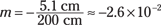
So the magnification is –2.6 × 10⁻². That tells you a few things. First, note that magnification is another of those relatively few quantities in physics that has no units — it’s just a multiplier. Second, the negative sign tells you that the image formed is upside down with respect to the object (did you know that camera images are inverted?). And third, it tells you that the magnification is very small, so you can capture big objects on small film surfaces or pixel arrays (of digital cameras).
Now take a look at the diverging lens. In the second problem I solve in “Going the distance with the thin-lens equation,” the focal length is –5.0 centimeters, and the object is placed 7.0 centimeters in front of it. The image forms at –2.9 centimeters. So what’s the magnification of the lens with this setup? You can use the magnification equation:

Plugging in the numbers here gives you this:
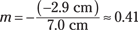
So although the image is upright, it’s still smaller than the object (putting it closer to the lens will result in magnification greater than 1).
Combining Lenses for More Magnification Power
You can use lenses together — in fact, that’s one of their most popular uses, in microscopes and telescopes and such. Lenses used in combination are almost always converging lenses. In this section, you look at how combining two lenses gives you more magnification power, and you see how such combinations usually work.
Understanding how microscopes and telescopes work
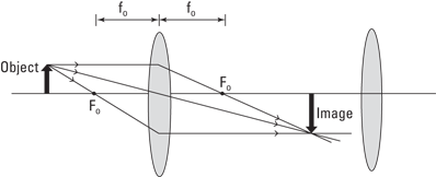
When you combine two converging lenses, the first lens is nearest the object, so it’s called the objective lens. As you can see in Figure 9-13, the object is farther away from the objective lens than the focal length (fo) of the objective lens. In a microscope, the object you’re looking at may not be much beyond the focal length, but in a telescope, the object is always much farther from the objective lens.
As you can see in the figure, rays from the tip of the object form an image past the focal length of the objective lens on the right side of the lens. This image is larger than the object, and it’s inverted — it’s also a real image.
Figure 9-13: The objective lens.
Seeing clearly with corrective lenses
Two common vision problems are nearsightedness, where people can focus only on near objects, and farsightedness, where people can focus only on objects farther away. Corrective lenses help with both — diverging lenses for nearsightedness and converging lenses for farsightedness.
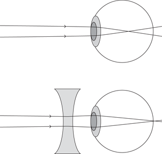
The diagram at the top of the following figure shows an uncorrected nearsighted eye. The problem here is that the lens of the eye tends to focus objects some distance in front of the retina. As a result, objects look blurry. The bottom diagram shows the same eye corrected with a diverging lens. Now the diverging lens makes the rays from objects diverge slightly to counteract the overly strong converging powers of the lens of the eye. As a result, the image comes into focus directly on the retina, as it should.
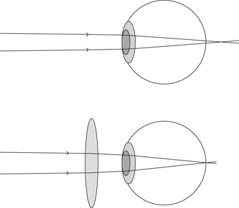
The diagram at the top of the next figure shows an uncorrected farsighted eye. Here, the problem is that the lens of the eye doesn’t converge light passing through it enough. As a result, the image forms past the retina. The solution is to use a converging lens, as in the bottom diagram. The converging lens makes the light rays from the object converge a little, which helps the lens of the eye focus the image, which appears on the retina.
Now here’s the clever part — the image from the objective lens becomes the object for the second lens. That is, the second lens looks at the image (which is real) just as though it were an actual object. Because light rays come together at the image, this works very well.
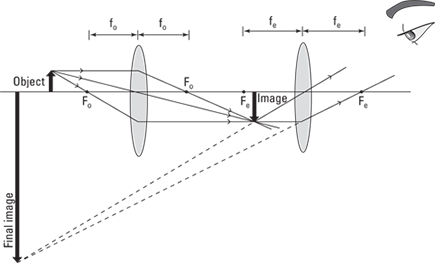
The second lens is called the eyepiece (not surprisingly, because that’s the lens that is closest to the eye). Everything is set up so that the first image, the one created by the objective lens, falls just inside the eyepiece’s focal length, fe. That ensures that the second lens magnifies the image to a very large size. You can see this in Figure 9-14.
This time, the eyepiece creates a virtual image (so you can see it by looking through the eyepiece, as with microscopes and telescopes). Thus, the final image ends up large and inverted, as you can see in Figure 9-14. But how large? What’s the magnification of such a combination of lenses?
Well, the image from the objective lens is magnified. Then this magnified image is the object for the eyepiece lens, which magnifies again. The total resulting magnification is the product of the magnification from each lens.
Figure 9-14: The eyepiece.
Here’s why it’s best to place the object not too far beyond the focal length of the objective lens in a microscope: If the object is between the center of curvature and the focal length of a convex lens (as I explain earlier in “X marks the spot: Finding images from convex lenses”), then the image is real and has a greater size than the object — and this size increases as the object approaches the focal length. In its normal operation, a microscope needs a real image from the object, and the larger this image, the greater the magnification.
Getting a new angle on magnification
Magnification for microscopes and for telescopes is often figured in terms of angular magnification. That is, the object you want to look at takes up a certain angle of your vision (for example, the moon takes up about half of a degree of the 360° you can see by turning completely around), and if you use a telescope, the object looks larger (the moon may take up what seems like three times the same angle). The symbol for angular magnification is M. In this section, you use some formulas to find the magnification of microscopes and telescopes.
Getting up close and personal with microscopes
Microscopes are typically made from two converging lenses in combination. Here, the object is between one and two focal lengths from the objective lens. If the distance between the objective lens and the eyepiece lens is L, then the angular magnification for a microscope turns out to be the following:

N is the distance to the near point for the eye. The near point is the closest you can hold, for example, some text and still read it. For a normal eye, N equals 25 centimeters.
Suppose you have an eyepiece with focal length of 5.0 centimeters and an objective lens with a focal length of 0.40 centimeters. The length between the two lenses, L, is 25.0 centimeters. What is the angular magnification of the microscope?
Plugging in the numbers — using N = 25.0 centimeters — gives you the answer:
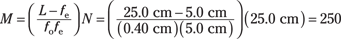
So the angular magnification of the microscope is 250.
Bringing the heavens near with telescopes
Like microscopes, optical telescopes are frequently made with two converging lenses. With telescopes, the object you’re looking at is a far distance away compared with the distance to the eye’s near point, N, and the focal length of the objective lens.
In this case, you can make some approximations, and the angular magnification of a telescope is about equal to the following:

Say, for example, that you have a telescope whose objective lens has a focal length of 100 centimeters and an eyepiece with the focal length of 0.5 centimeters. What angular magnification will the telescope give you?
You can use the angular-magnification equation and plug in numbers like this:
So the angular magnification of the telescope is about –200, where the negative sign simply means that the image is inverted.