Chapter 10
Bouncing Light Waves: Reflection and Mirrors
In This Chapter
Looking at reflections from flat mirrors
Understanding images from curved mirrors
Finding distances and magnifications
You can say a lot about mirrors — both plane (straight) mirrors and trickier spherical mirrors. As for spherical mirrors, you can get images in both concave mirrors (mirrors that look like the inside of a bowl) and convex mirrors (mirrors that look like the outside of the mirrored bowl). You can predict where images will form and whether they’ll be upright or upside down — no mean feat, given that those mirrors can act pretty wacky when you hold them in your hand (or put them on a funhouse wall).
In this chapter, you work with some basic properties of reflection, and you see how light bounces off both flat and curved surfaces. After you see some ray diagrams, I present a couple of equations so you can get down with the math.
The Plane Truth: Reflecting on Mirror Basics
Even people with the most casual disregard for their appearance probably see themselves in a mirror every day. The flat plane mirror you use so frequently is also extremely important to optics. The basic law of how light reflects is expressed in terms of how light bounces off a plane mirror. Then, if you take any curved reflecting surface — like the ones in a carnival’s hall of mirrors — and look at it closely enough, it appears flat at every point (just as the Earth is curved, but because you see it so close up, it appears flat wherever you’re on it). So if you know how light reflects off a flat surface, you also know how light reflects off every part of any curved surface — bargain!
This idea applies wherever reflection occurs from a flat surface, even if it’s not a mirror. So without further ado, here’s your introduction to mirrors and other reflective surfaces.
 Mirrors were often made of polished metal in the ancient world. These days, they’re commonly made of metal electroplated onto glass. And glass itself can form a partial mirror — if you stand next to a window and look out, you often see a ghostly image of yourself looking out in the window glass. You see that image because glass commonly reflects about 7 percent of the light that hits it instead of transmitting it through the glass.
Getting the angles on plane mirrors
Figure 10-1 shows a plane mirror — that is, a straight mirror — lying on its back. A light ray comes in from upper left in the figure, hits the mirror, bounces off the mirror, and leaves to the upper right.
The angle at which the light ray comes in to the mirror is called the angle of incidence, θi, and the angle at which light is reflected is called the angle of reflection, θr. Note that these angles are with respect to the normal — a normal is a line perpendicular to the mirror’s surface.
Figure 10-1: Reflection in a plane mirror.
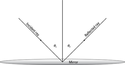
 The angle of incidence is equal to the angle of reflection:
θi = θr
That’s why when you’re driving and you see an approaching car’s image in your rear-view mirror, you know just which way to turn to see the actual car.
Forming images in plane mirrors
Plane mirrors are especially good at forming images. This section takes a look at image formation in a little more depth.
Mirrors form virtual images of objects, as you see in Figure 10-2. The image is virtual because no actual light rays meet to form that image (see Chapter 9 for more on virtual versus real images). In other words, you can’t focus the image on a screen at the place the image appears to come from.
Figure 10-2: Image formation in a plane mirror.
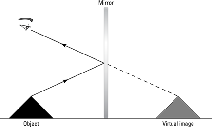
Here’s a set of observations you can make about an image formed in a plane mirror, besides the fact that it’s virtual:
The image is upright.
The image is the same size as the object.
The image is located as far behind the mirror as the object is in front of the mirror.
The image is flipped back to front (see the nearby sidebar “Reversing a mirror myth: the left-right flip”).
Finding the mirror size
Many stores sell full-length mirrors, but that may be more about making profit than about image-formation necessity. In this section, I show that a plane mirror only needs to be one-half your actual height to let you see yourself fully in a mirror. To see this, start with a picture — Figure 10-3:
A person (represented by a thick black line) is standing to the left of a plane mirror. The line representing the person includes points labeling the position of the top of the head (T), the eyes (E), and the feet (F). (Note: To make the diagram clearer, the position of the eyes is shown much lower than it actually is — unless the person is wearing a top hat!)
The vertical gray shaded line in the center represents a full-length plane mirror.
The light rays leaving the person reflect from the mirror, creating an image, which is shown on the right as another thick, black line. The image has corresponding points labeled, showing the position of the image’s top of the head (T'), eyes (E'), and feet (F').
The points A and B show where on the mirror’s surface the person sees the top of his or her head and feet, respectively. You can already tell that you don’t need the whole length of this mirror to see all of yourself, because the distance AB is much less than the length of the mirror, CD. With a little geometry, you can work out exactly how big AB is — that is, how much of the full-length mirror you really need.
Figure 10-3: A person standing in front of a mirror.

Look again at Figure 10-3. You can see that the mirror is obeying the law of reflection: The angles of incidence and reflection from the rays from the top of your head, α, are equal. Then, because T'E is a straight line, the angle that it makes with your image must also be α. This means that the triangle T'ET is similar to triangle T'AD — because they’re both right triangles that also share the angle α.
You also know that the image is as far behind the mirror as you are in front of it, so T'A is half the length of T'E. Because you have similar triangles, that means triangle T'AD is half the size of T'ET — which means that AD is half the length of ET:

You can do exactly the same thing for triangles F'EF and F'BC, because you can see that they’re similar for the same reason. So BC is half the length of EF:

Now all you have to do to find the length of mirror you actually need is to subtract these two unused lengths (AD and BC) from the total (CD):
AB = CD – AD – BC
Now try some numbers. If your height (TF) is 1.66 meters, how big does the mirror have to be so you can see your full length in the mirror? The full-length mirror, CD, is likewise 1.66 meters. Suppose your eyes are 0.06 meters below the top of your head (ET). That means the distance from eyes to feet is then TF – ET = 1.60 meters. You can now work out the length of the part of the mirror that you use:

This is half your height — you don’t need a full-length mirror; you only need a half-length mirror.
Note that you may have seen this much more quickly by noticing that the triangle T'F'E is similar to triangle ABE and that ABE must be half the size of T'F'E (because the image is as far behind the mirror as the object is in front). Therefore, AB must be half the length of T'F'. Then, because your image is the same size as you are, AB is just half your height!
Working with Spherical Mirrors
A plane mirror makes an image that’s the same size as the original object, at a position that’s as far behind the mirror as the object is in front. When the mirror is curved, then the position, size, and orientation of the image can be very different. The inside or outside surface of a sphere creates such images. This is a convenient shape of mirror to study because it’s simple, though you usually use only part of the surface of a sphere rather than the whole.
 There are only two ways of looking at spherical mirrors — as convex and concave. Remember, if you’re looking into a mirrored “cave,” that’s a concave mirror. Otherwise, it’s convex.
Like lenses (see Chapter 9), spherical mirrors have a center of curvature. That’s the center of the sphere that the mirror was cut from, and it’s marked C in Figure 10-4. The distance from the center of curvature, C, to the mirror is called the radius of curvature, R. There’s also a focal point, marked F. The focal point is where light rays that come in horizontally from the left end up being focused. The focal length is half of the radius of curvature, or looked at another way, R = 2f.
How do you handle spherical mirrors? You can draw ray diagrams that trace how several light rays travel from an object, bounce off the mirror, and end up forming an image (just as for lenses, which I cover in Chapter 9). In this section, I show you how to draw ray diagrams for both concave and convex mirrors.
Figure 10-4: A spherical mirror.

Getting the inside scoop on concave mirrors
For a concave mirror, the part of the mirror that does the reflecting is on the inside of the spherical mirror. For concave mirrors, three different cases yield different types of images:
The object is out farther than the center of curvature.
The object is between the center of curvature and the focal point.
The object is located between the focal point and the mirror itself.
This section takes a look at the various possibilities, starting by placing the object beyond the center of curvature and finding where the image forms.
Object farther out than the center of curvature
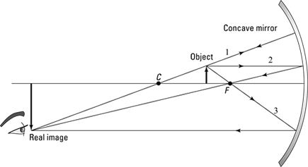
Figure 10-5 shows an object (represented by the thick arrow) being reflected in a concave mirror. Look at the ray diagram to see where the image will form in this situation and whether it’s upright or upside down. Here’s how the rays work:
Ray 1: The first ray goes from the tip of the object to the mirror, where it bounces off and then goes through the center of curvature. Obviously, the center of curvature of a sphere is the center of the sphere, and any straight line passing through the center of a sphere is normal (perpendicular) to its surface, so this light ray strikes the mirror with an angle of incidence of zero. The angle of reflection is the same, so the ray is just sent back the way it came.
Ray 2: The second ray goes from the tip of the object through the focal point, and then it gets reflected in a horizontal direction — that’s the key for Rays 2 and 3: These rays alternate between going through the focal point and going horizontally.
Ray 3: The third ray starts off from the tip of the object in a horizontal direction, bounces off the mirror, and ends up going through the focal point.
The rays meet to form an image that’s inverted with respect to the object, between the radius of curvature and the focal point.
Is this image real or virtual? It’s real, because it forms on the side of the mirror where the object is — that’s where the rays are present physically (virtual images form on the other side of the mirror, where no light rays from the object are actually present). If you bring a screen up to the location of the image, you see the image focused there — that’s what makes it a real image.
Figure 10-5: An object farther out than the mirror’s center of curvature.

Object between the center of curvature and the focal point
Figure 10-6 shows an object being reflected in a concave mirror when the object is placed between the center of curvature and the focal point. Here’s how to draw the three rays in the figure:
Ray 1: The first ray goes from the tip of the object through the center of curvature to the mirror, where it’s reflected back on its same path.
Ray 2: The second ray travels from the tip of the object horizontally until it hits the mirror. Then it’s reflected — and as is usual for rays that hit the mirror horizontally, it gets reflected through the focal point.
Ray 3: The third ray travels from the tip of the object through the focal point, then to the mirror. When it’s reflected from the mirror, the ray is traveling horizontally.
What’s the net result? As you can see in Figure 10-6, the image is real (on the same side of the mirror as the object), inverted with respect to the object, and out past the center of curvature.
Object between the focal point and the mirror
Now for something really different — you end up with a virtual image in this case. If you place an object between the focal point of a spherical mirror and the mirror itself, all the rules change, because rays from the object can’t pass through the focal point and then bounce off the mirror anymore.
Figure 10-6: An object between the center of curvature and the focal point.
As you can see in Figure 10-7, you’re dealing with three rays:
Ray 1: The first ray goes from the tip of the object to the center of curvature, and you extend the ray back to the mirror to complete this ray.
Ray 2: The second ray goes from the tip of the object horizontally to the mirror — then it reflects from the mirror and goes through the focal point.
Ray 3: The third ray is the tricky one. Normally, this ray goes from the tip of the object through the focal point and ends up going horizontally, but that’s not going to work here, because if you send this ray through the focal point, it’ll never hit the mirror. Instead, you send this ray from the tip of the object to the mirror as though it were coming from the focal point, as you can see in Figure 10-7. That does the trick.
Where do these rays come together? That’s a trick question, because they don’t come together at all — you have to extend the reflected rays behind the mirror itself. And with mirrors, that’s the mark of a virtual image (that is, no light rays from the object penetrate behind the mirror, so the image that forms there is not actually caused by light rays that meet there — you can’t bring a screen there and focus the image). So the image is virtual — and upright and magnified — as you see in the figure.
So the next time you’re creating a salad in a mirrored metal bowl, take a look at what happens when you bring the lettuce close to the metal. As you pass the focal point, the image of the lettuce suddenly snaps into focus as upright and enlarged — and you get an image of some mega-sized lettuce.
Figure 10-7: An object between the focal point and the mirror.
Smaller and smaller: Seeing convex mirrors at work
Turn a mirrored bowl over so you’re looking at the bottom of the bowl, and you have a convex mirror. Instead of bending light toward you, convex mirrors bend light away.
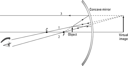
So what happens if you bring an object near a convex mirror? You can see the answer in ray diagrams in Figure 10-8. This time, the focal point and the center of curvature are on the other side of the mirror, so there’s no question of different placement here (such as placing the object between the focal point and the center of curvature, placing the object closer than the focal point to the mirror, and so on). You can place the object only as Figure 10-8 shows — on the other side from the focal point and center of curvature.
You have the same three rays as with concave mirrors (see the preceding sections), but using them takes some fancy footwork. Here goes:
Ray 1: The first ray goes from the tip of the object toward the center of curvature — but note that the center of curvature is on the other side of the mirror this time. That means that this ray goes from the tip of the object to the mirror and then bounces off in a way that it would as if it were coming from the center of curvature.
Ray 2: The second ray travels from the tip of the object horizontally and then bounces off the mirror in a way that makes it appear this ray is coming from the focal point, as you can see in the figure.
Ray 3: The third ray goes toward the focal point, which is on the other side of the mirror, and then bounces off the mirror, ending up going horizontally.
The result of all this? As you can see in the figure, the image is virtual (on the opposite side of the mirror from the object, where no light rays go), upright, and smaller than the object. Cool.
Figure 10-8: Using a convex mirror.

The Numbers Roundup: Using Equations for Spherical Mirrors
Just as with the lenses (see Chapter 9), you can work out the location, size, and orientation of an image made by a spherical mirror with a couple of simple equations. These equations derive only from the law of reflection (the angle of incidence is equal to the angle of reflection) applied to every point of the curved surface of the mirror. But you don’t have to worry about that here — I just give you the equations and show you how they work.
In this section, the mirror equation shows how the distances from the curved mirror to the object (do) and the distance from the mirror to the image (di) relate to the mirror’s focal length (f). I also show you how to find magnification (m) when you know both do and di.
Getting numerical with the mirror equation
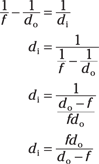
An equation for mirrors, cleverly called the mirror equation, relates the distance from the object to the mirror (do) and the distance from the mirror to the image (di) to the mirror’s focal length (f). Here it is:

You may notice that, yep, this looks a lot like the thin-lens equation from Chapter 9. However, you have two ideas that are different from the thin-lens equation to keep in mind:
The distance to the image, di , is negative if the image is on the other side of the mirror from the object. That is, di is negative if the image is virtual.
The focal length, f, for convex mirrors is negative (that’s just like the rule that the focal length for diverging lenses is negative, as I explain in Chapter 9).
The sign rules for mirrors are essentially the same as those for lenses: If the image is on the outgoing side (the side into which the rays are reflected by the mirror), the image distance is positive; otherwise, it’s negative — just as for the lens. The sign rule for the focal length is reversed for mirrors because a convex mirror diverges parallel light rays — as does a concave lens — and vice versa.
di for an object between the focal length and the center of curvature
Try some numbers. Say you have a concave mirror that has a focal length of 5.0 centimeters, and you place an object 8.0 centimeters in front of it. Where does the image form? Start with the mirror equation:

Solve for the image distance, di, by rearranging the equation, combining the fractions, and simplifying:
Plugging in the numbers gives you the answer:
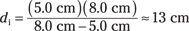
So the result is positive, which means the image is real.
di for an object between the mirror and the focal length
How about this one? Say you have a concave mirror with a focal length of 5.0 centimeters, and you place an object 3.0 centimeters in front of it. Where does the image form? Use the mirror equation solved for the distance to the image (from the preceding section) like this:

Plugging in the numbers gives you the following:

So in this case, the distance to the image is negative — which means that image is virtual. That’s as expected, because in this case, you’re placing an object between a concave mirror and its focal point.
di for a convex mirror
Here’s one more. Say this time that you have a convex mirror (not concave) with a focal length of –5.0 centimeters, and you place an object 7.0 centimeters in front of it — where does the image appear?
Note that in this case, the focal length is negative, which it must be for a convex mirror. You can use mirror equation solved for the image distance, di, like this:

Putting in the numbers gives you

So in this case, the image is virtual.
Discovering whether it’s bigger or smaller: Magnification
The magnification equation gives you the amount an image is magnified with respect to the object — that is, the ratio of the image height over the object height. This equation for mirrors is just the same as it is for lenses, which I cover in Chapter 9:

where di is the distance to the image and do the distance to the object.
Doing a magnification example
Suppose an object is 7.0 centimeters from a convex mirror (do = 7.0 centimeters). The mirror has a focal length of –5.0 centimeters, and your calculations (from the preceding section) tell you that di = –2.9 centimeters. What’s the magnification of the image compared to the object? Use the magnification equation:

Putting in the numbers gives you the answer:

In this case, the magnification is 0.41 — the image height is 0.41 times the object height, and the image is upright (because the magnification is positive). Remember: Magnification doesn’t always mean that the image is larger — the image here is smaller than the object (less than half the size).
Using the mirror equation and magnification equation together
In general, you have to use the mirror equation to find do first; then you can plug that into the magnification equation to find the magnification.
Say that you have a concave mirror, with a focal length of 8.0 centimeters, and you place an object 10.0 centimeters in front of it. What’s the magnification of the image? First, you have to find the distance to the image. Use the equation mirror equation, solved for di:

In this example, you get
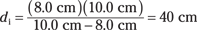
So di = 40 centimeters — it’s positive, so the image is real. That means that the magnification is
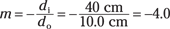
So the magnification is –4.0 — that is, the image is four times the height of the object. The magnification is negative, which tells you that the image is inverted.
So now you know everything about what’s happening in this example — where the image appears, whether it’s upright or inverted, whether it’s real or virtual, and how big i is. Not bad for two little equations (the mirror equation and the magnification equation).