Chapter 11
Shedding Light on Light Wave Interference and Diffraction
In This Chapter
Understanding light wave interference
Getting coherent light sources
Looking at diffraction from a single slit
Working with the multiple slits of diffraction gratings
Finding resolving power when light passes through a hole
This chapter is all about interference — that is, what happens when light waves collide. Interference is a property of all waves (as you discover in Chapter 6). Because light waves are actually electromagnetic waves, their electric and magnetic fields can add or subtract if they overlap with each other. The resulting electric fields and magnetic fields can be stronger — or weaker — than the fields of either light wave alone, giving rise to some phenomena you may not expect. This chapter starts with the interference of two light waves and goes on from there.
Interference is the interaction of waves from a few sources, but the interference of waves from a great many sources is called diffraction. I discuss diffraction of sound waves in Chapter 7, where sound waves bend and spread when they fall upon a gap in a wall. In this chapter, you become much more familiar with diffraction for light waves, using Huygens’s principle. This is a new way of thinking about how waves propagate, and it explains why they can bend around corners and spread out when they pass through gaps in walls. Huygens’s principle shows how diffraction is really just the interference of a lot of waves and not something completely new.
When Waves Collide: Introducing Light Interference
When two or more light waves interfere with each other, it’s called just that — interference. Interference occurs when the electric and magnetic fields of two or more light waves interact. The electric and magnetic fields of the two waves add together to give you a new wave.
 To see interference, you have to have two light sources, one for each wave, that emit light of exactly the same wavelength. If you don’t, then the relative phase between the light waves will change with time, and you won’t see constructive interference (where the fields are in the same direction, resulting in an even stronger field) or destructive interference (where the fields are in the opposite direction and cancel each other out).
When two light sources emit the same wavelength of light continuously, they’re called coherent sources. This is the importance of coherent light — it makes the interference effects of light observable:
To get constructive interference, you need the peaks of the waves to line up.
To get destructive interference, you need the peak of one wave to line up with the trough of another.
But generally, to get interference, you just need there to be a constant relation between the two phases. This can only come from coherent waves. In this section, you see how constructive and destructive interference work when you have two coherent light sources.
Meeting at the bars: In phase with constructive interference
Because light is indeed an electromagnetic wave, you know that it’s made up of electric and magnetic fields. Figure 11-1 presents the electric fields for two light waves. Note what happens when they both end up at the same place, which I call point P, at the same time. As you can see, the two waves I’m adding are in phase. That means that when they meet, the peaks of one wave add to the peaks of the other, and the troughs of one wave add to the troughs of the other. That is, when two waves are in phase, they meet peak-to-peak and trough-to-trough.
The electric fields of the light waves simply add. The two waves have equal amplitude, so the resulting wave’s peaks are twice as high, and its troughs are twice as low.
When you add two light waves from coherent sources, their electric and magnetic fields add linearly. This is called the principle of linear superposition.
Figure 11-1: Adding two in-phase light waves together.
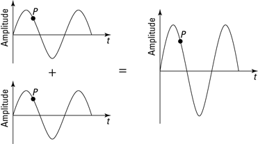
When two light waves collide as they do in Figure 11-1, peak-to-peak and trough-to-trough, and each light wave has the same wavelength (so they keep adding peak-to-peak and trough-to-trough as time goes on), the result is larger than either of the two waves by themselves; this process is called constructive interference. With constructive interference, the resulting light wave is stronger than either of its two components.
So if the two light waves that add in Figure 11-1 are in phase, the magnitude of the electric field from Wave 1 at point P is
E1 = Eo sin(ωt)
And the magnitude of the electric field of light Wave 2 at point P is
E2 = Eo sin(ωt)
That is, they reach their peaks and troughs at the same time, so they’re in phase. When both these waves are present, then the total electric field is given by
E1 + E2 = 2E0 sin(ωt)
This is just a wave which has the same frequency but twice the amplitude. This sum of the two waves is the linear superposition.
Going dark: Out of phase with destructive interference
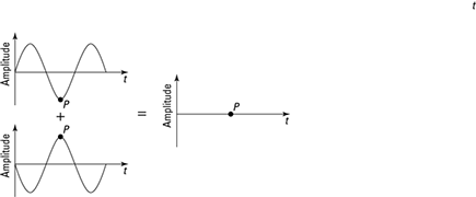
Two waves don’t need to meet peak-to-peak. They can meet out-of-phase, as Figure 11-2 shows. The waves are meeting at some point P, peak-to-trough and trough-to-peak. In other words, just when one wave is at its highest, the one it’s interfering with is at its lowest, and vice versa.
In particular, the two waves in Figure 11-2 are as out of phase as they can be. They add together and cancel each other out. There’s nothing left — they’re opposites of each other, and when they meet, the result is zero. When two waves cancel each other out like that, that’s called destructive interference.
Figure 11-2: Subtracting two out-of-phase light waves.

Does this come in a medium?
In the 19th century, people thought that light, being a wave, must be carried by a medium. They believed that just as sound waves were carried by air, light waves were carried by a medium called luminiferous ether.
In 1887, Albert Michelson and Edward Morley used the following setup — an interferometer — and got a result that puzzled physicists. Michelson and Morley used this experiment to measure the movement of the Earth through the ether. They shone a beam of coherent light toward a semi-silvered mirror (S) that let half of the light pass straight through to the mirror at point M2 while half reflected up toward the mirror at point M1. The two parts of this separated beam were reflected back from these mirrors and recombined, having traveled in the two directions at 90° to each other. The mirror at M1 could be moved so that these beams destructively or constructively interfered — that is, the path-length difference, 2(l1 – l2), was a whole number of wavelengths (constructive interference) or that plus half a wavelength (destructive interference). The light waves should travel with constant speed with respect to the ether.
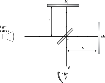
Suppose the setup was arranged so that the beams destructively interfered. The experimenters expected that the speed of the light in each direction would depend on the motion of the Earth through the ether. This would mean that when the mirror was rotated 90°, there should be a difference in the relative phases and they should no longer have destructive interference. But Michelson and Morley saw no difference whatsoever! This could only mean that there was no ether. Only when Einstein developed the special theory of relativity (which I cover in Chapter 12) did this result make sense.
In contrast to the waves in Figure 11-1, the two light waves in Figure 11-2 are as out of phase as possible. So if the first one looks like this at point P:
E1 = Eo sin(ωt)
then the magnitude of the electric field of Wave 2 at point P is
E2 = Eo sin(ωt + π)
In these equations, when one wave is hitting its peak, the other is hitting its trough. They’re out of phase by an angle of π — and that’s as out of phase as you can get.
When both these waves are present, then the total wave that results is just the sum:
E1 + E2
= E0 sin(ωt) + E0 sin(ωt + π)
= E0 sin(ωt) – E0sin(ωt)
= 0
So you see that the two waves cancel out. The linear superposition of the two waves results in no wave at all.
Interference in Action: Getting Two Coherent Light Sources
Generally, when a number of waves interfere with each other, there are places where constructive interference occurs and other places where destructive interference occurs (see the earlier section “When Waves Collide: Introducing Light Interference” for info on types of interference). The result is a pattern of bright and dark areas, with intermediate brightness in between. This makes a pattern called the interference pattern.
Generally, to be able to see the interference pattern, you need to have a constant phase difference between the waves. For this, you need coherent light sources, which give you light waves that are of the same frequency. So how do you get two coherent light sources in the first place? In this section, I discuss two methods: sending light from a single source through two slits or sending light through a thin film, using principles of reflection and refraction to split the light for you. I also show you the arrangement of the light and dark areas of the interference pattern in these cases.
Splitting light with double slits
Before the invention of lasers, one clever way to get two coherent light sources was to use the same source for both light rays by sending light through a double-slit arrangement.
If you send light of a particular color (and therefore of a particular wavelength) through the double slits, the two slits then act as two coherent light sources — each with the same wavelength. This kind of setup is called Young’s double-slit experiment (credited to Thomas Young), and it provided some early proof of the wave nature of light. In this section, you see how double slits produce an interference pattern, predict where constructive and destructive interference occur, and look at some numbers.
Getting an interference pattern
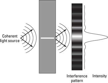
When you send light from a single source through two slits, you now have two coherent light sources (the two slits, as Figure 11-3 shows). Those slits are arranged so that light from them falls on a screen, which you see at the right of the figure.
Figure 11-3: Light passing through two slits gives you light and dark bands of light.
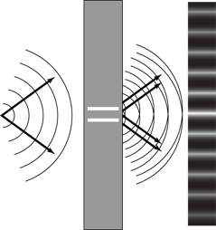
Say that light from one slit illuminates a specific spot on the screen. Then light from the other slit falls on the same spot on the screen, and the two light waves interfere. Do they interfere constructively or destructively? That depends on how far the spot is from each of the two slits:
Constructive: If the spot being illuminated is an integral number of light wavelengths from one slit, mλ, and it’s nλ from the other slit (where m and n are integers and n can equal m), then the two light waves hit the spot in phase — peak-to-peak, trough to trough. You end up with constructive interference, which causes a bright spot on the screen.
Destructive: If the spot is at a distance from one slit that is an integral number of wavelengths, mλ, and the distance to that spot from the other slit is an integral number of wavelengths plus one-half wavelength, (n + 1//2)λ from the other slit (where m and n are integers), then the two waves meet at the spot exactly out of phase, so there’s destructive interference. The result is a dark spot.
You can see this situation more clearly in Figure 11-4. There, the distance between the slits is d, and the slits are a distance L from the screen. The curve at the screen represents the light intensity at every point (intensity is related to the mean of the squared electric field — see Chapter 8). The resulting light and dark regions, called the interference pattern, appears on the screen at right.
Figure 11-4: The schematic for a double-slit setup.
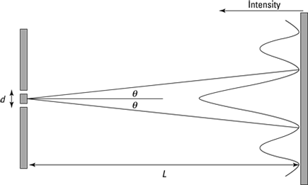
The figure shows that you have a central bright bar, which is equidistant from the two slits, where constructive interference occurs. Then as θ increases, you have destructive interference between the rays from the two slits, and you get a dark bar. Then you get another light bar as the light rays end up in phase again — note that this light bar is less bright than the central bar.
That’s what the interference pattern looks like — a central bright bar (also called a fringe) surrounded by dark bars and then alternating with successively diminishing light and dark bars. Here’s how the naming of these bars works:
The central bright bar is called the zeroth-order bright bar (or zeroth-order bright fringe).
The next bright bar over is called the first-order bright bar. You have two of these, one on either side of the zeroth-order bright bar.
The next bright bar is called the second-order bright bar, and so on.
Predicting where you get dark and light spots
Take a closer look at the double slits and the angle involved in Figure 11-5. To predict whether you end up with a light spot or a dark spot on the screen at a certain angle θ, you have to know the difference in how far that spot is from the two slits.
So what’s the difference in the distance the light travels from each slit to the same spot on the screen? That difference in distance is marked as Δd in Figure 11-5. Because the screen is a long way from the slits, you can assume the two light rays are parallel, so each is emitted from their respective slits at the same angle θ. You also make the assumption that d is much less than L, the distance from the screen.
Figure 11-5: A close-up of double slits.
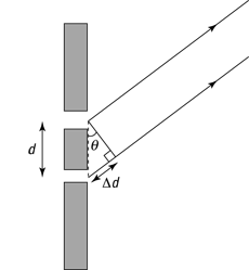
As you can see in the figure, the difference in distances from the two slits to the same spot of the screen is
Δd = d sin θ
So sin θ is equal to

Note that when Δd is an integral number of wavelengths, you end up with constructive interference, which means that for all the bright bands in the interference pattern, the following equation holds true:

And when Δd is an integral number of wavelengths plus one-half wavelength, you end up with destructive interference and a dark band on the screen. So for destructive interference, you have this relation:

So now you have a handle on whether you get a bright bar or a dark bar at a certain angle from the two slits.
Trying some numbers for double slits
Say that you shine red light (λ = 713 nanometers) on two slits a distance of 2.00 × 10⁻⁴ meters apart, and an interference pattern appears on a screen 2.50 meters away. How far is it from the zeroth-order bright bar in the center of the interference pattern on the screen to the third-order bright bar?
For bright bars (constructive interference), this is the equation to use:

In this case, you can find the angle between the zeroth-order bright bar and the third-order bright bar by setting m equal to 3:

Convert the wavelength to meters to get λ = 713 nanometers = 7.13 × 10⁻⁷ meters. Putting in the wavelength and the distance between the slits gives you
Taking the inverse sine gives you θ:
θ = sin–1(1.07 × 10⁻²) ≈ 0.613°
That’s a pretty small angle, but perhaps it’ll come to something when you take into account how far away the screen is.
You know that the distance between the slits and the screen is 2.50 meters. That length forms the horizontal side of a right triangle where the vertical side is the distance between the bright bars that you’re looking for and the angle between those two sides is θ. That means that if y is the length you’re looking for, you have the following:

Plugging in the numbers and doing the math gives you the answer:
y = (2.50 m) tan(0.613°) ≈ 2.67 × 10⁻² m
So the distance between the central bright bar and the third-order bright bar is 2.67 centimeters, which is roughly an inch. As you can see, even though red light has a very small wavelength, 7.13 × 10⁻⁷ meters, you still get a measureable effect when you position the screen far enough away from the double slits and position the double slits close enough together.
Gasoline-puddle rainbows: Splitting light with thin-film interference
Ever see some oily liquid like gasoline spilled on a puddle of water? If so, you probably saw rainbows of color form in the layer of gasoline. This same effect is responsible for the rainbows you see in soap bubbles. What you’re really seeing is constructive and destructive interference patterns for different wavelengths of light — the constructive interference leads to a bright band of color. In this section, you take a look at how this process works — it’s called thin-film interference.
Sending light rays on different paths
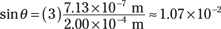
Suppose you have light going from air (where the index of refraction is na = 1.00) to gasoline (ny = 1.40) and then to the underlying layer of water (nw = 1.33), as Figure 11-6 shows (I discuss indexes of refraction in Chapter 9). At each step, there’s some reflection, as you see in the figure — and the two rays heading off to the right end up interfering with each other, much as if they came from two coherent light sources.
Figure 11-6: Refraction and reflection produce two parallel rays of light that interfere with each other.
Here’s a blow-by-blow description of what happens with thin-film interference:
1. Light travels through air to start, coming in from the upper left.
2. The light hits the air-gasoline boundary.
Some of the light is reflected from the boundary and heads off to the upper right.
Most of the light continues into the gasoline and is refracted toward the normal (a perpendicular line) to the gasoline-air boundary.
3. The light reaches the gasoline-water boundary, and some of the light bounces off the gasoline-water boundary and is reflected.
4. The reflected light hits the gasoline-air boundary.
Some light goes through the gasoline-air boundary and is refracted away from the normal. It ends up parallel to but horizontally displaced from the other light ray going off to the right.
5. The two light rays that end up going off to the right interfere with each other, and the difference in the lengths of their paths (one ray goes through the gasoline) means that they can be out of phase.
When that path-length difference for the two waves is a multiple of the light’s wavelength, you get constructive interference, and hence that region of the film is bright.
With thin-film interference, you assume that the thin film has a uniform thickness, but in practice, this isn’t true — the thickness of a thin film of gasoline or soapy water in a soap bubble actually varies somewhat from place to place, which is why you get bands of color instead of one uniform color.
Accounting for changes in the wave’s phase
When working with thin-film interference, you have to take one more effect into account besides the difference in path length: a phase change in the wave.
If you tie a rope to a wall and whip one end of the rope up and down, a pulse travels along the string to the wall. When it hits the wall, the rope reflects the pulse back — but first, the pulse is inverted. That is, it suffers a phase change of exactly one-half wavelength. So the pulse travels to the wall, hits the wall, gets inverted, and travels back to you, assuming there’s some tension in the rope. On the other hand, if the end of the rope is just hanging free, a pulse is still at least partially reflected from the end of the rope, but there’s no phase change.
Something similar happens to light at boundaries between materials that have different indexes of refraction:
Low to high: When light, traveling through a medium, reflects from an interface with a material of higher refractive index (such as light in air reflecting from gasonline), there’s a phase change in the reflected light of half a wavelength — half of the wavelength that the light would have in the material with the higher index of refraction.
High to low: When light, traveling through a medium, reflects from an interface with a material of lower refractive index (such as light in gasoline reflecting from water), there’s no phase change in the reflected light.
When this phase change occurs, you have to take it into account — it’s as if the light ray traveled an additional one-half wavelength. Here’s how you show that mathematically:
Doing some thin-film interference calculations
Say that there you are, filling up your car with gasoline, and notice that the previous customer was a little careless — some gasoline landed on a puddle next to your car. On closer inspection, you see that the film looks yellowish, and the time is just about noon, so the sunlight is hitting the gasoline film just about vertically. What’s happening, and what minimum thicknesses of gasoline film on the water gives you this result?
Sunlight is pretty white because it’s made up of all the wavelengths you normally see, from red to violet. The eye perceives white light with most of the blue part removed as yellow light, so if you see reflected sunlight from the gasoline film as yellowish, a lot of blue must be missing. (This is why the white sun ends up looking yellow — most of the blue wavelengths have been scattered away to make the sky blue!)
In other words, the gasoline film is just thick enough to give you destructive interference of blue light (which has a wavelength in air of 469 nonmeters). Wonderful, you’re on your way to solving this problem.
What conditions give you destructive interference of the blue light? Well that’s simple — if the light ray labeled A in Figure 11-6 is out of phase with Ray B, then they destructively interfere.
How does this phase difference come about? First, it happens because Ray B travels a greater distance than Ray A, because Ray B has to travel to the bottom of the gasoline film and reflect back up — a distance of about twice the thickness of the film. If the thickness of the film is t, then Ray B travels an extra distance of 2t compared to Ray A. As it travels this distance, Ray B makes a number of wave cycles that’s equal to the number of wavelengths of the light in the distance traveled. For example, if the film is one wavelength thick, then Ray B goes through two cycles as it travels to the bottom and reflects back up (remember the extra distance covered is 2t).
If Ray B goes through a whole number of cycles as it travels through the film of gasoline, then

where λgas is the wavelength of the blue light in the gasoline and m is a whole number.
If this is the case, then Ray A and Ray B are in phase and constructively interfere, right? Nope. You need to account for the phase shifts that can occur when light reflects. Ray B reflects from within the gasoline film off the gas-water surface (Step 3 in the preceding section). But because water has a lower refractive index than gas, there’s no phase shift for this ray. However, Ray A reflects from the air off the air-gasoline surface (Step 2). Because the gasoline has a higher refractive index, this ray undergoes a phase shift of half a cycle. So in this case, Ray A and Ray B are now out of phase when the preceding equation holds, in which case the rays destructively interfere.
All you need to do now is work out the wavelength of the blue light in gasoline. The key is to realize that the frequency of the light is always the same, whatever the material it’s traveling through. Only its speed and wavelength change for different refractive indexes.
If you take the equation for the refractive index of a material and divide the top and bottom of the fraction by the frequency, f, you get the following:

But because you know that the wavelength is just the speed divided by the frequency, you can write this as

Rearrange this and write an equation for the wavelength of the light in gasoline:

Put in the numbers to work out the wavelength of the blue light in gasoline. You know the wavelength of the blue light in air is λair = 469 nm and the refractive index of gasoline is ngas = 1.40, so
At last you can work out how thick the gasoline film needs to be to give you destructive interference for the blue light and so make the sunlight appear yellow. From earlier in this section, you know that the thickness has to be related to the wavelength of the blue light in gasoline by

The minimum occurs when m = 1, in which case the thickness of the film is
So there you have it — the gasoline film needs to be 168 nanometers thick so that you see yellow light in the puddle.
Single-Slit Diffraction: Getting Interference from Wavelets
People usually think of light traveling in straight lines. However, in certain circumstances, light can bend around corners to reach places it couldn’t go if it traveled only in a straight line (just as sound waves can bend around corners; see Chapter 7). You don’t usually notice this effect because the small wavelengths of light usually make this bending quite small.
This bending, called diffraction, comes from the interference of a very large number of waves. In this section, I explain why light spreads out when it passes through a single slit, and you see the strange patterns of light and dark created when it does. You also discover a way to use this effect to make precise measurements of wavelength.
Huygens’s principle: Looking at how diffraction works with a single slit
Figure 11-7 shows a single slit and the intensity of light as it appears on a screen some distance away from the single slit. How on Earth do you get interference from a single slit? This process is called diffraction, and it depends on the idea that every point on the front of a wave acts like a coherent source of light. All those point sources that make up a wave front are responsible for the interference pattern.
Figure 11-7: Single-slit diffraction.
Diffraction all comes about because of Huygens’s principle, which says the following:
“Every point on a wave front acts as a source of wavelets that move forward with the speed of the overall wave; at any later time, the wave is that surface that is tangent to all the moving wavelets.”
So every point of the wave front going through a single slit (of some width W), as you see in Figure 11-8, acts as a coherent source of wavelets. If that light then strikes a screen, the result of all the wavelets is a pattern of light like the one in Figure 11-7 — a wide central bright bar or fringe, flanked by successively smaller bright bars, with dark bars in between them. If light didn’t obey Huygens’s principle, then you’d get no pattern from a single slit — you’d just see the image of the single slit on the far screen.
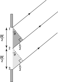
Figure 11-8: A schematic for the first dark bar with single-slit diffraction.
Getting the bars in the diffraction pattern
So how do you get dark bars in the diffraction pattern when you have light going through a single slit? This section explains where all those dark bars come from.
Arriving at the first dark bar
Look back at Figure 11-8. There, light traveling from the top of the slit, Point 1, arrives at the screen exactly out of phase by one-half wavelength from light traveling from Point 2. That means that the light from Points 1 and 2 cancel each other out on the screen, interfering with each other destructively. (See the earlier section “Going dark: Out of phase with destructive interference” for the basics on destructive interference.)
In fact, every ray of light from the top of the slit is canceled out by a ray of light from the bottom half of the slit, which arrives exactly one-half wavelength out of phase — so you get the first dark bar in the diffraction pattern.
Think of the slit in Figure 11-8 in two equal sections. Consider the wave from Points 1 and 2. You get destructive interference between these two waves if they have a path-length difference of half a wavelength. The shaded right triangle shows that the path-length difference between these two waves is then given by

Then the waves from every point between 1 and 2 destructively interfere with the wave from the corresponding point between 2 and 3. So you can write the angle of the first dark band as

Most of the light passing through the slit falls in the central bright region, between the first dark bars. Notice that the width of this region is inversely proportional to the width of the slit — the narrower the slit, the greater the angle over which this light is spread. Because the angle depends on the ratio of wavelength to the width of the slit, the diffraction pattern becomes noticeable only when the width of the slit is not too much greater than the wavelength of the light (so that λ/W is not too tiny). The wavelength of light is quite small by everyday standards, which explains why you don’t normally notice this effect and most people think of light traveling in straight lines. (But check out the nearby sidebar “Street smarts: A light interference experiment” for a really cool way you can actually see this interference pattern.)
Getting to the second dark bar and beyond
Take a look at the situation in Figure 11-9, where you have light passing through a single slit and you’re creating the second dark bar in the diffraction pattern. Light rays from Point 1 are canceled by light rays from Point 2, which arrive at the screen exactly one-half wavelength out of phase. Light from Point 3 is canceled by light from Point 4, and so on.

Figure 11-9: A schematic for the second dark bar with single-slit diffraction.
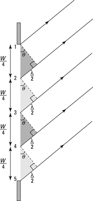
Here, you can see the relation that connects W, λ, and θ from the triangle whose two short sides are W and 2λ. If you look at the shaded triangle between Points 1 and 2, then you have destructive interference if the path-length difference is given by

This applies to any point and the corresponding point W/4 down from it. So then you can say that the angle of the second dark band is given by

You can progress to higher-order dark bars as well, and you end up with this equation, which gives you the angle at which dark bars appear on the screen:

So there you have it — now if you know the width of a single slit, you can figure out where the dark bars will appear in the diffraction pattern. And because the central bright bar is straddled by first-order dark bars, you can figure out the width of the central bright bar as well.
Doing diffraction calculations
Say that you have a single slit width, W = 5.0 × 10⁻⁶ meters, and it’s L = 0.5 meters away from a screen. You shine blue light (λ = 469 nanometers) on the single slit. What is the width of the central bright bar in the diffraction pattern?
The central bright bar is straddled by first-order dark bars, so if the distance to the first dark bar is y, then the width of the central bright bar is 2y. So all you need to find is the distance to the first dark bar, and you can use the following equation for that:

For the first dark bar, m =1. A nanometer is a billionth of a meter, so 469 nanometers = 4.69 × 10⁻⁷ meters. So here’s what you have for the first dark bar:

Taking the inverse sine gives you the angle:
θ = sin–1(0.094) ≈ 5.4°
So that’s the angle at which the first dark bar appears. You still need to find y, the distance of the first dark bar from the center of the diffraction pattern. Because the distance to the screen is L, you have the following equation:

which you can rearrange like this:
y = L tan θ
Because L = 0.50 meters, you have
y = (0.50 m) tan 5.4° ≈ 0.047 m
Okay, so the first dark bar appears at 0.047 meters, or 4.7 centimeters, from the center of the diffraction pattern. You need to find 2y to get the width of the central bright bar, so multiply by 2 to get
2y = 2 (4.7 cm) = 9.4 cm
So in this case, the central bright bar is 9.4 centimeters wide. Cool.
Multiple Slits: Taking It to the Limit with Diffraction Gratings
A diffraction grating has many slits — hundreds, thousands of slits. You’re far beyond double slits now. A diffraction grating has so many slits that they’re measured in slits per centimeter — and 40,000 slits per centimeter is not unusual for a diffraction grating. That’s a lot of slits.
Diffraction gratings are frequently made from plates of glass or something equally transparent and are incised with a diamond-tipped, machine-controlled scribe. The scribe draws lines to the tune of 40,000 per centimeter. The slits are the clear places between the lines.
A diffraction grating works in the same way as single slits and double slits — through interference. Each slit acts as a coherent source of light. In this section, you see how diffraction gratings work and how physicists use them to separate colors.
Separating colors with diffraction gratings
Diffraction gratings are great for determining exactly which wavelength of light you’re dealing with. When you have a single slit or double slit, the bright bars you get on the screen are pretty broad, making accurate measurements of the angle (and hence, the wavelength) difficult. If you’re trying to find the exact center of a bright bar that’s 4.0 centimeters in width, there’s a lot of room for error.
Diffraction gratings are different, however. You end up with very sharp, very narrow bright bars, which are called maxima (plural of maximum) in diffraction-grating speak. The bright bars from a single slit are wide, those from a double slit are a little less wide, and the bright bars from a diffraction grating are razor thin.
Besides the main bright bars in the pattern generated by a diffraction grating, you also have some other, secondary bars due to the diffraction of light passing through each of the single slits. But although the secondary bright bars are significant when you have a double-slit setup, they’re almost invisible when you’re using a diffraction grating. All you see are the principal maxima.
To get a maximum in the diffraction grating pattern, light from the top slit travels from that slit to the screen. Light from the next slit down must travel that same distance plus one wavelength. Light from the next slit down must travel the same distance as from the top slit to the spot on screen, plus two wavelengths, and so on. When light travels a distance that’s one wavelength longer than the path from the slit directly above it, you have constructive interference — that is, a maximum — at that spot.
By analogy with what I show you earlier for single and double slits in the sections “Splitting light with double slits” and “Single-Slit Diffraction: Getting Interference from Wavelets,” you get the following relation for maxima in diffraction grating patterns:

where d is the distance between the slits in the grating and θ is the angle from the center of the diffraction grating to the spot on the screen you’re looking at. Looking at this relation, you can see that you have a central maximum (m = 0), another maximum right next to it (m = 1), and then other maxima (m = 2, 3, and so on).
Trying some diffraction-grating calculations
Say that you have a diffraction grating with 10,000 slits per centimeter and that you send a mixture of light through it, half violet light (θ = 410 nanometers) and half red light (θ = 660 nanometers). Try showing that the diffraction grating breaks down the light so that the two components, red and violet, are clearly separated.
To solve this problem, you can find the first-order maximum for each color of light, red and violet, and show that their angles vary significantly. For the first-order maxima, m = 1 in this relation:

So if m = 1, you have

What’s the angle for the first-order maximum? Taking the inverse sine gives you

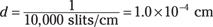
So when the diffraction grating has 10,000 slits per centimeter, that means that the distance between each slit is
For violet light, you have the following (410 nm = 4.1 × 10⁻⁵ cm):
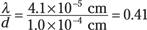
And taking the inverse sine of this gives you
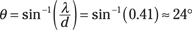
For red light, you have the following (660 nm = 6.6 × 10⁻⁵ cm):
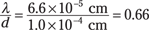
And taking the inverse sine of this gives you
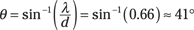
So the first principal maximum from violet light is at about 24°, and the first principal maximum from red light is at about 41° — that’s a very wide separation in angle, so you can tell quite clearly the makeup of the light you’re studying.
Seeing Clearly: Resolving Power and Diffraction from a Hole
Here’s an interesting point: Light traveling through the lens of a camera treats that lens much as it would a single slit, only in circular form, which means you end up with a single-slit diffraction pattern on the film — that is, the image appears a little blurry because of single-slit diffraction (see the earlier section “Single-Slit Diffraction: Getting Interference from Wavelets” for details on diffraction).
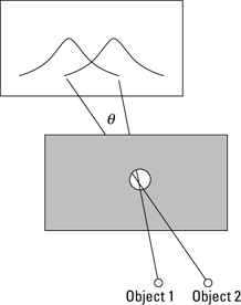
In Figure 11-10, light from two objects is passing through a circular aperture (much like a lens) and falling on a screen. So how small can you make the circular aperture and still be able to distinguish between the two objects on the screen? In other words, how small can you make the hole and still see the images of the two objects as separate? This value is known as the resolving power of a circular aperture.
The rule is that you’re just about at the limit of resolving power for two objects when the first dark bar from one image overlaps the central bright bar of the second image, as Figure 11-10 illustrates.
Figure 11-10: Resolving power, where an image’s first dark bar overlaps another image’s central bright bar.
If the first dark bar of one image overlaps the central bright bar of the other image, doesn’t that dim the bright bar? No, not at all. Keep in mind that a dark bar in a diffraction pattern doesn’t mean a shadow or anything like that — it just means that no light comes from the corresponding source at that point. So when the first image’s dark bar overlaps a bright bar, it just means that no light from the first image falls there.
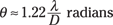
When the first dark bar of one image overlaps the central bright bar of the other image, the angle between the light rays from the two objects turns out to be the following:

where θ is the angle (which represents the minimum angle between two objects such that you can still distinguish them), λ is the wavelength of the light, and D is the diameter of the aperture. So for a particular diameter of circular aperture and a particular wavelength, θ is the minimum angular separation between two objects such that you can still see them as distinct.
For example, if two objects are 100 meters away from you, how far apart must they be from each other so that you can still tell them apart? For this example, work with green light, which is the exact center of the visible spectrum, λair = 555 nanometers. The pupil of your eye is about 3.0 millimeters.
So are you ready to use the resolving-power equation? Not quite, because although you know the wavelength of light you’re working with in air, you don’t know the wavelength of that light where it counts — in the eye. To figure that out, use the equation derived earlier in “Doing some thin-film interference calculations”:

where λeye is the wavelength of the light in the eye. The index of refraction of the clear medium in the eye turns out to be pretty close to water — 1.36 (compared to 1.33 for water). So plugging in the numbers, you get the following wavelength:
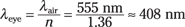
Now you’re ready to find the resolving power. Note that for small angles, sin θ = θ if you measure θ in radians, so you have the following equation for resolving power:
The eye’s pupil is 3.0 millimeters, or 3.0 × 10⁶ nanometers. Plugging in the numbers gives you the answer:

So you can resolve (theoretically) an angle of 1.7 × 10⁻⁴ radians. If you’re 100 meters from the objects, what does that work out to be in terms of distance? With such a small angle, the distance the angle translates to is just the angle (in radians) multiplied by how far away you are, so you have the following:
(1.7 × 10⁻⁴)(100 m) = 1.7 × 10⁻² m
So from 100 meters away, you can (theoretically) resolve two objects as distinct if they’re at least 1.7 centimeters apart.