Chapter 11
Winding Up with Angular Kinetics
In This Chapter
![]() Changing gears from linear motion to rotational motion
Changing gears from linear motion to rotational motion
![]() Calculating tangential speed and acceleration
Calculating tangential speed and acceleration
![]() Understanding angular acceleration and velocity
Understanding angular acceleration and velocity
![]() Identifying the torque involved in rotational motion
Identifying the torque involved in rotational motion
![]() Maintaining rotational equilibrium
Maintaining rotational equilibrium
This chapter is the first of two on handling objects that rotate, from space stations to marbles. Rotation is what makes the world go round — literally — and if you know how to handle linear motion and Newton’s laws (see the first two parts of the book if you don’t), the rotational equivalents I present in this chapter and in Chapter 12 are pieces of cake. And if you don’t have a grasp on linear motion, no worries. You can get a firm grip on the basics of rotation here. You see all kinds of rotational ideas in this chapter: angular acceleration, tangential speed and acceleration, torque, and more. Kinetics deals not only with the motions of objects but the forces behind those motions. Rotational kinetics deals with rotational motions and the forces behind them (torque). But enough spinning the wheels. Read on!
Going from Linear to Rotational Motion
You need to change equations when you go from linear motion to rotational motion. Here are the angular equivalents (or analogs) for the linear motion equations:
|
Linear |
Angular |
|
|
Velocity |
|
|
|
Acceleration |
|
|
|
Displacement |
|
|
|
Motion with time canceled out |
vf2 – vi2 = 2as |
ωf2 – ωi2 = 2αθ |


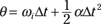
In all these equations, t stands for time, Δ means “change in,” f means final, and i means initial. In the linear equations, v is velocity, s is displacement, and a is acceleration. In the angular equations, ω is angular velocity (measured in radians/second), θ is angular displacement in radians, and α is angular acceleration (in radians/second2).
You know that the quantities displacement, velocity, and acceleration are all vectors; well, their angular equivalents are vectors, too. First, consider angular displacement, Δθ — this is a measure of the angle through which an object has rotated. The magnitude tells you the size of the angle of the rotation, and the direction is parallel to the axis of the rotation. Similarly, angular velocity, ω, has a magnitude equal to the angular speed and a direction that defines the axis of rotation. The angular acceleration, α, has a magnitude equal to the rate at which the angular velocity is changing; it’s also directed along the axis of rotation.
If you consider only motion in a plane, then you have only one possible direction for the axis of rotation: perpendicular to the plane. In this case, these vector quantities have only one component — this vector component is just a number, and the sign of the number indicates all you need to know about the direction. For example, a positive angular displacement may be a clockwise rotation, and a negative angular displacement may be a counterclockwise rotation.
Just as the magnitude of the velocity is the speed, the magnitude of the angular velocity is the angular speed. Just as the magnitude of a displacement is a distance, the magnitude of an angular displacement is an angle — that is, the magnitude of the vector quantity is a scalar quantity.
Note: In the next section, I begin by looking at the motion in a plane considering only the single component of the vectors — which are scalar numbers (I identify the vector with its single component). So for that section, the quantities, Δθ, ω, and α don’t appear in bold type because they represent the single component of a rotation in a plane. In the section “Applying Vectors to Rotation,” I take a closer look at the vector nature of the angular displacement, velocity, and acceleration.
Understanding Tangential Motion
Tangential motion is motion that’s perpendicular to radial motion, or motion along a radius. Given a central point, vectors in the surrounding space can be broken into two components: radial direction, which points directly away from the center of the circle, and tangential direction, which follows the circle and is directed perpendicular to the radial direction. Motion in the tangential direction is referred to as tangential motion.
 You can tie angular quantities such as angular displacement (θ), angular velocity (ω), and angular acceleration (α) to their associated tangential quantities. All you have to do is multiply by the radius, using these equations:
 s = rθ
v = rω
a = rα
 These equations rely on using radians as the measure of angles; they don’t work if you try to use degrees.
Say you’re riding a motorcycle, for example, and the wheels’ angular speed is ω = 21.5π radians per second. What does this mean in terms of your motorcycle’s speed? To determine your motorcycle’s velocity, you need to relate angular velocity, ω, to linear velocity, v. The following sections explain how you can make such relations.
Finding tangential velocity
At any point on a circle, you can pick two special directions: The direction that points directly away from the center of the circle (along the radius) is called the radial direction, and the direction that’s perpendicular to this is called the tangential direction.
When an object moves in a circle, you can think of its instantaneous velocity (the velocity at a given point in time) at any particular point on the circle as an arrow drawn from that point and directed in the tangential direction. For this reason, this velocity is called the tangential velocity. The magnitude of the tangential velocity is the tangential speed, which is simply the speed of an object moving in a circle.
 Given an angular velocity of magnitude ω, the tangential velocity at any radius is of magnitude rω. The idea that the tangential velocity increases as the radius increases makes sense, because given a rotating wheel, you’d expect a point at radius r to be going faster than a point closer to the hub of the wheel.
Take a look at Figure 11-1, which shows a ball tied to a string. The ball is whipping around with angular velocity of magnitude ω.
Figure 11-1: A ball in circular motion has angular speed with respect to the radius of the circle.

You can easily find the magnitude of the ball’s velocity, v, if you measure the angles in radians. A circle has 2π radians; the complete distance around a circle — its circumference — is 2πr, where r is the circle’s radius. In general, therefore, you can connect an angle measured in radians with the distance you cover along the circle, s, like this:
s = rθ
where r is the radius of the circle. Now, you can say that v = s/t, where v is magnitude of the velocity, s is the distance, and t is time. You can substitute for s to get

Because ω = θ/t, you can say that

In other words,
v = rω
Now you can find the magnitude of the velocity. The wheels of a motorcycle are turning with an angular velocity of 21.5π radians/second. If you can find the tangential velocity of any point on the outside edges of the wheels, you can find the motorcycle’s speed. Say, for example, that the radius of one of your motorcycle’s wheels is 40 centimeters. You know that v = rω, so just plug in the numbers:
v = rω = (0.40 m/s)21.5π ≈ 27 m/s
Converting 27 meters/second to miles/hour gives you about 60 mph.
Finding tangential acceleration
Tangential acceleration is a measure of how the tangential velocity of a point at a certain radius changes with time. Tangential acceleration is just like linear acceleration (see Chapter 3), but it’s particular to the tangential direction, which is relevant to circular motion. Here you look at the magnitude of the angular acceleration, α, which tells you how the speed of the object in the tangential direction is changing.
For example, when you start a lawn mower, a point on the tip of one of its blades starts at a tangential velocity of zero and ends up with a tangential velocity with a pretty large magnitude. So how do you determine the point’s tangential acceleration? You can use the following equation from Chapter 3, which relates velocity to acceleration (where Δv is the change in velocity and Δt is the change in time) to relate tangential quantities like tangential velocity to angular quantities such as angular velocity:

Tangential velocity, v, equals rω (as you see in the preceding section), so you can plug in this information:

Because the radius is constant here, the equation becomes

However, Δω/Δt = α, the angular acceleration, so the equation becomes
a = rα
Translated into layman’s terms, this says tangential acceleration equals angular acceleration multiplied by the radius.
Finding centripetal acceleration
Newton’s first law says that when there are no net forces, an object in motion will continue to move uniformly in a straight line (see Chapter 5). For an object to move in a circle, a force has to cause the change in direction — this force is called the centripetal force. Centripetal force is always directed toward the center of the circle.
The centripetal acceleration is proportional to the centripetal force (obeying Newton’s second law; see Chapter 5). This is the component of the object’s acceleration in the radial direction (directed toward the center of the circle), and it’s the rate of change in the object’s velocity that keeps the object moving in a circle; this force does not change the magnitude of the velocity, only the direction.
You can connect angular quantities, such as angular velocity, to centripetal acceleration. Centripetal acceleration is given by the following equation (for more on the equation, see Chapter 7):

where v is the velocity and r is the radius. Linear velocity is easy enough to tie to angular velocity because v = rω (see the section “Finding tangential velocity”). Therefore, you can rewrite the acceleration formula as

The centripetal-acceleration equation simplifies to
ac = rω2
Nothing to it. The equation for centripetal acceleration means that you can find the centripetal acceleration needed to keep an object moving in a circle given the circle’s radius and the object’s angular velocity.
Say that you want to calculate the centripetal acceleration of the moon around the Earth. Start with the old equation

First you have to calculate the tangential velocity of the moon in its orbit. Alternatively, you can calculate the tangential velocity from the angular velocity. Using the new version of the equation, ac = rω2, is easier because the moon orbits the Earth in about 28 days, so you can easily calculate the moon’s angular velocity.
Because the moon makes a complete orbit around the Earth in about 28 days, it travels 2π radians around the Earth in that period, so its angular velocity is
Converting 28 days to seconds gives you the following:

Therefore, you get the following angular velocity:

You now have the moon’s angular velocity, 2.60 × 10⁻⁶ radians per second. The average radius of the moon’s orbit is 3.85 × 10⁸ meters, so its centripetal acceleration is
ac = rω2
= (3.85 × 10⁸ m)(2.60 × 10⁻⁶ s–1)2
≈ 2.60 × 10⁻³ m/s2
In the preceding equation, the units of angular velocity, radians per second, are written as s–1 because the radian is a dimensionless unit. A radian is the angle swept by an arc that has a length equal to the radius of the circle. Think of it as a particular portion of the whole circle; as such, it has no dimensions. So when you have “radians per second,” you can omit “radians,” which leaves you with “per second.” Another way to write this is to use the exponent –1, so you can represent radians per second as s–1.
Just for kicks, you can also find the force needed to keep the moon going around in its orbit. Force equals mass times acceleration (see Chapter 5), so you multiply acceleration by the mass of the moon, 7.35 × 10²² kilograms:
Fc = mac = (7.35 × 10²² kg)(2.60 × 10⁻³ m/s2) ≈ 1.91 × 10²⁰ N
The force in newtons, 1.91 × 10²⁰ N, converts to about 4.3 × 10¹⁹ pounds of force needed to keep the moon going around in its orbit.
Applying Vectors to Rotation
Angular displacement, angular velocity, and angular acceleration are each vector quantities. When you consider circular motion in a plane, these vectors only have one component, which is a scalar number; in that case, you don’t have to consider the direction very much. However, when you have circular motion in more than one plane (as with the motions of the planets, which orbit on very slightly different planes) or when the plane of rotation changes (like in a wobbling spinning top, for example), then the direction of these vectors becomes significant.
Angular velocity and angular acceleration are vectors that are directed along the axis of the rotation.
In this section, you hear more about the directions of the angular vectors. For the rest of this section, the quantities  ,
,  , and
, and  appear in bold type because you’re explicitly dealing with vectors.
Calculating angular velocity
When a wheel is spinning, it has not only an angular speed but also a direction. Here’s what the angular velocity vector tells you:
The size of the angular velocity vector tells you the angular speed.
The direction of the vector tells you the axis of the rotation, as well as whether the rotation is clockwise or counterclockwise.
Say that a wheel has a constant angular speed, ω — which direction does its angular velocity,  , point? It can’t point along the rim of the wheel, as tangential velocity does, because its direction would then change every second. In fact, the only real choice for its direction is perpendicular to the wheel.
The direction of the angular velocity always takes people by surprise: Angular velocity,  , points along the axle of a wheel (see Figure 11-2). Because the angular velocity vector points the way it does, it has no component along the wheel. The wheel is spinning, so the tangential (linear) velocity at any point on the wheel is constantly changing direction — except for at the very center point of the wheel, where the base of the angular velocity vector sits. If the wheel is lying flat on the ground, the vector’s head points up or down, away from the wheel, depending on which direction the wheel is rotating.
You can use the right-hand rule to determine the direction of the angular velocity vector. Wrap your right hand around the wheel so that your fingers point in the direction of the tangential motion at any point — the fingers on your right hand should go in the same direction as the wheel’s rotation. When you wrap your right hand around the wheel, your thumb points in the direction of the angular velocity vector,  .
.
Figure 11-2 shows a wheel lying flat, turning counterclockwise when viewed from above. Wrap your fingers in the direction of rotation. Your thumb, which represents the angular velocity vector, points up; it runs along the wheel’s axle. If the wheel were to turn clockwise instead, your thumb — and the vector — would have to point down, in the opposite direction.
Figure 11-2: Angular velocity points in a direction perpen-dicular to the wheel.

Figuring angular acceleration
In this section, you find out how the angular acceleration and angular velocity relate to each other in terms of their magnitude and direction. You first see what happens in the simplest case, where the angular acceleration and velocity are in the same direction or in opposite directions. Then you look at a situation in which angular acceleration and angular velocity are at an angle to each other, leading to a tilting of the rotational axis.
Changing the speed and reversing direction
If the angular velocity vector points out of the plane of rotation (see the preceding section), what happens when the angular velocity changes — when the wheel speeds up or slows down? A change in velocity signifies the presence of angular acceleration. Like angular velocity,  , angular acceleration,
  , is a vector, meaning it has a magnitude and a direction. Angular acceleration is the rate of change of angular velocity:

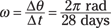
For example, look at Figure 11-3, which shows what happens when angular acceleration affects angular velocity. In this case,  points in the same direction as
  in 11-3A. When the angular acceleration vector,
  , points along the angular velocity,
  , the magnitude of
  will increase as time goes on, as Figure 11-3B shows.
Figure 11-3: Angular acceleration in the same direction as the angular velocity.
Just as an object’s linear velocity and linear acceleration may be in opposite directions, the angular acceleration also doesn’t have to be in the same direction as the angular velocity vector (as Figure 11-4A shows). If the angular acceleration is directed in the opposite direction of the angular velocity, then the magnitude of the angular velocity decreases at a rate given by the magnitude of the angular acceleration.
Just as in the case of linear velocity and acceleration, the angular acceleration gives the rate of change of angular velocity: The magnitude of the angular acceleration gives the rate at which the angular velocity changes, and the direction gives the direction of the change. You can see a decreased angular velocity in Figure 11-4B.
Figure 11-4: Angular acceleration in the direction opposite the angular velocity reduces the angular speed.

Tilting the axle
The angular acceleration is the rate of change of angular velocity — the change can be to the direction instead of the magnitude. For example, suppose you take hold of the axle of the spinning wheel in Figure 11-3 and tilt it. You’d change the angular velocity of the wheel but not by changing its magnitude (the angular speed of the wheel would remain constant); rather, you’d change the direction of the angular velocity by changing the axis of rotation — this is an angular acceleration that’s directed perpendicular to the angular velocity, as in Figure 11-5.
Figure 11-5: Angular acceleration perpendicular to the angular velocity tilts the axis of rotation.

Doing the Twist: Torque
For extended objects (rods, disks, or cubes, for example), which, unlike point objects, have their mass distributed through space, you have to take into account where the force is applied. Enter torque. Torque is a measure of the ability of a force to cause rotation. In physics terms, the torque exerted on an object depends on the force itself (its magnitude and direction) and where you exert the force. You go from the strictly linear idea of force as something that acts in a straight line (such as when you push a refrigerator up a ramp) to its angular counterpart, torque.
Just as force causes acceleration, torque causes angular acceleration, so you can think of torque as the angular equivalent of force (see Chapter 12 for more info on that aspect of torque).
Torque brings forces into the rotational world. Most objects aren’t just points or rigid masses, so if you push them, they not only move but also turn. For example, if you apply a force tangentially to a merry-go-round, you don’t move the merry-go-round away from its current location — you cause it to start spinning. Rotational motions and the forces behind them are the focus of this chapter and Chapter 12.
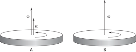
Look at Figure 11-6, which shows a seesaw with a mass m on it. If you want to balance the seesaw, you can’t have a larger mass, M, placed on a similar spot on the other side of the seesaw. Where you put the larger mass M determines whether the seesaw balances. As you can see in Figure 11-6A, if you put the mass M on the pivot point — also called the fulcrum — of the seesaw, you don’t have balance. The larger mass exerts a force on the seesaw, but the force doesn’t balance it.
As you can see in Figure 11-6B, as you increase the distance you put the mass M away from the fulcrum, the balance improves. In fact, if M = 2m, you need to put the mass M exactly half as far from the fulcrum as the mass m is.
Figure 11-6: A seesaw demonstrates torque in action.
The torque is a vector. The magnitude of the torque tells you the ability of the torque to generate rotation; more specifically, the magnitude of the torque is proportional to the angular acceleration it generates. The direction of the torque is along the axis of this angular acceleration. This section starts by considering torques and forces that are in a plane, so you only need to think about the magnitude of the torque and not the full vector. Later, I explain a little more about the direction of the torque vector.
Mapping out the torque equation
How much torque you exert on an object depends on the following:
The force you exert, F
Where you apply the force; the lever arm — also called the moment arm — is the perpendicular distance from the pivot point to the point at which you exert your force and is related to the distance from the axis, r, by l = r sin θ, where θ is the angle between the force and a line from the axis to the point where the force is applied.
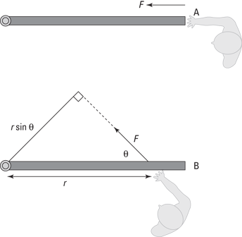
Assume that you’re trying to open a door, as in the various scenarios in Figure 11-7. You know that if you push on the hinge, as in diagram A, the door won’t open; if you push the middle of the door, as in diagram B, the door will open; but if you push the edge of the door, as in diagram C, the door will open more easily.
In Figure 11-7, the lever arm, l, is distance r from the hinge at which you exert your force. The torque is the product of the magnitude of the force multiplied by the lever arm. It has a special symbol, the Greek letter τ (tau):
τ = Fl
The units of torque are force units multiplied by distance units, which is newton-meters in the MKS system and foot-pounds in the foot-pound-second system (see Chapter 2 for more on these measurement systems).
For example, the lever arm in Figure 11-7 is distance r (because this is the distance perpendicular to the force), so τ = Fr. If you push with a force of 200 newtons and r is 0.5 meters, what’s the torque you see in the figure? In diagram A, you push on the hinge, so your distance from the pivot point is zero, which means the lever arm is zero. Therefore, the magnitude of the torque is zero. In diagram B, you exert the 200 newtons of force at a distance of 0.5 meters perpendicular to the hinge, so
τ = Fl = (200 N)(0.5 m) = 100 N·m
Figure 11-7: The torque you exert on a door depends on where you push it.

The magnitude of the torque here is 100 newton-meters. But now take a look at diagram C. You push with 200 newtons of force at a distance of 2r perpendicular to the hinge, which makes the lever arm 2r or 1.0 meter, so you get this torque:
τ = Fl = (200 N)(1.0 m) = 200 N·m
Now you have 200 newton-meters of torque, because you push at a point twice as far away from the pivot point. In other words, you double the magnitude of your torque. But what would happen if, say, the door were partially open when you exerted your force? Well, you would calculate the torque easily, if you have lever-arm mastery.
Understanding lever arms
If you push a partially open door in the same direction as you push a closed door, you create a different torque because of the non-right angle between your force and the door.
Take a look at Figure 11-8A to see a person obstinately trying to open a door by pushing along the door toward the hinge. You know this method won’t produce any turning motion, because the person’s force has no lever arm to produce the needed turning force. In this case, the lever arm is zero, so it’s clear that even if you apply a force at a given distance away from a pivot point, you don’t always produce a torque. The direction you apply the force also counts, as you know from your door-opening expertise.
Figure 11-8: You produce a useful angle of a lever arm by exerting force in the proper direction.
Figuring out the torque generated
Generating torque is how you open doors, whether you have to quickly pop a car door or slowly pry open a bank-vault door. But how do you find out how much torque you generate? First, you calculate the lever arm, and then you multiply that lever arm by the force to get the torque.
Take a look at Figure 11-8B. You apply a force to the door at some angle, θ. The force may open the door, but it isn’t a sure thing, because as you can tell from the figure, you apply less of a turning force here. What you need to do is find the lever arm first. As you can see in Figure 11-8B, you apply the force at a distance r from the hinge. If you apply that force perpendicularly to the door, the lever arm’s length would be r, and you’d get
τ = Fr
However, that’s not the case here, because the force isn’t perpendicular to the door.
The lever arm is the effective distance from the pivot point at which the force acts perpendicularly. Picture moving the point where the force is applied, carrying the force vector along without changing its direction. When you move to a spot where the force is perpendicular to the direction of the axis of rotation, the distance to the axis is the lever arm.
To see how this works, take a look at diagram B in Figure 11-8, where you can draw a lever arm from the pivot point so that the force is perpendicular to the lever arm. To do this, extend the force vector until you can draw a line from the pivot point that’s perpendicular to the force vector. You create a new triangle. The lever arm and the force are at right angles with respect to each other, so you create a right triangle. The angle between the force and the door is θ, and the distance from the hinge at which you apply the force is r (the hypotenuse of the right triangle), so the lever arm becomes
l = r sin θ
When θ goes to zero, so does the lever arm, so there’s no torque (see diagram A in Figure 11-8). You know that τ = Fl, so you can now find τ = Fr sin θ, where θ is the angle between the force and the door.
This is a general equation; if you apply a force with a magnitude of F at a distance r from a pivot point, where the angle between that displacement vector r and the force vector F is θ, the torque you produce will have a magnitude of τ = Fr sin θ. So, for example, if θ = 45°, F = 200 newtons, and r = 1.0 meter, you get
τ = Fr sin θ = (200 N)(1.0 m)(0.707) ≈ 140 N·m
This number is less than you’d expect if you just push perpendicularly to the door (which would be 200 newton-meters).
Recognizing that torque is a vector
Torque is a vector, so it has not only magnitude but also direction. The direction of the torque is the same as the angular acceleration that it causes. It is perpendicular to the force and the lever arm in a right-hand fashion.
To get a little more technical, torque is given by the cross-product of the vector that points from the axis of rotation to the point at which the force is applied, r, and the force vector, F. The cross-product is written as an ×, so mathematically, the torque vector is the following:
 = r × F
This equation is really a fancy mathematical way of saying that the torque vector has a magnitude of rF sin θ and that the direction of the torque vector is as Figure 11-9 shows.
The right-hand rule is a useful way of remembering the direction of torque. If you point the thumb of your right hand in the direction of the radius vector r and your fingers in the direction of the force vector F, then your palm faces the direction of the torque vector .
Figure 11-9: A turning motion toward larger positive angles indicates a positive vector.

Spinning at Constant Velocity: Rotational Equilibrium
You may know equilibrium as a state of balance, but what’s equilibrium in physics terms? When you say an object has equilibrium, you mean that the motion of the object isn’t changing; in other words, the object has no acceleration (it can have motion, however, as in constant velocity and/or constant angular velocity). As far as linear motion goes, the vector sum of all forces acting on the object must be zero for the object to be in equilibrium. The net force acting on the object is zero: ΣF = 0.
Equilibrium occurs in rotational motion in the form of rotational equilibrium. When an object is in rotational equilibrium, it has no angular acceleration — the object may be rotating, but it isn’t speeding up or slowing down or changing directions (its tilt angle), which means its angular velocity is constant. When an object has rotational equilibrium, you see no net turning force on the object, which means that the net torque on the object must be zero:
Στ = 0
This equation represents the rotational equivalent of linear equilibrium. Rotational equilibrium is a useful idea because given a set of torques operating on an extended object, you can determine what torque is necessary to stop the object from rotating. In this section, you try out three problems that involve objects in rotational equilibrium.
Determining how much weight Hercules can lift
Say that Hercules wants to lift a massive dumbbell using the deltoid (shoulder) muscle in his right arm and hold the weight at arm’s length. His arm, which has a weight of magnitude Fa = 28.0 newtons, can exert a force F of 1,840 newtons. His deltoid muscle is attached to the arm at 13.0°, as Figure 11-10 shows. The figure also shows the distances between the pivot point and the points of application of the forces: The distance to the muscle is 0.150 m, to the effective point of application of the weight of the arm is 0.310 m (half the length of the arm), and to the dumbbell is 0.620 m. The weight of the dumbbell has magnitude Fd.
Figure 11-10: A schematic of the forces acting on Hercules’s arm.
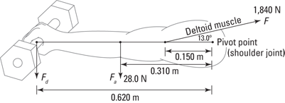
What is the maximum weight of the dumbbell Hercules can hold at arm’s length, and what are the two components of the force Fb, the force against his body? Because Hercules is holding the dumbbell without accelerating, the net force acting must be zero, so Fb must cancel out the sum of the forces in Figure 11-10.
Hercules’s arm is not moving, so ΣF = 0 and Σ = 0. Look at ΣF = 0 first. In the x direction, that gives you the following force against Hercules’s body:
ΣFx = Fbx + F cos 13.0° = 0
Fbx = –F cos 13.0°
Plugging in the value of force F gives you
Fbx = (–1,840 N) cos 13.0° ≈ –1,790 N
That was pretty easy. Already you have Fbx, which is –1,790 newtons. Now find the force against Hercules’s body in the y direction:
ΣFy = Fby + F sin 13.0° – Fa – Fd = 0
Fby + (1,840 N) sin 13.0° – 28.0 N – Fd = 0
Fby = –(1,840 N) sin 13.0° + 28.0 N + Fd
Well, that gives you one equation in two variables, Fby and Fd, so you need more information to solve for those variables.
Torque to the rescue. You can get that additional information with the equation Σ = 0. If you look at Figure 11-10, you see that three forces are acting on the arm to cause torques around the arm joint: the y component of F (the pull of Hercules’s deltoid muscle), Fa (the weight of his arm), and Fd (the weight of the dumbbell).
The component of F in the y direction is Fy = (1,841 N) sin 13.0°. The magnitude of the weight of Hercules’s arm is Fa = 28.0 newtons, and you don’t yet know the magnitude of the weight of the dumbbell, Fd.
So what are the torques due to these three torque-causing forces? The direction of the torque is in the direction perpendicular to the plane of Figure 11-10. Consider the component of the torque in this direction, such that positive values correspond to counterclockwise-acting torques and negative values correspond to clockwise-acting torques. Because this component of the torque vectors is a number (scalar), I don’t write it in bold type. The torque from the y component of the muscle-pull F is the following:
τM = Fy (0.150 m)
= (1,840 N) sin 13.0° (0.150 m)
This torque is positive because it leads to a turning force in the counterclockwise direction, as Figure 11-10 shows (or you can reason that the torque is positive because the angle between the force and the lever is θ = 90°, so l = r sin θ = (0.150 m) sin 90° = 0.150 m). The torque from the weight of Hercules’s arm is
τa = (28.0 N)(–0.310 m)
This torque is negative because the lever arm is negative, so the force causes a clockwise torque, as Figure 11-10 shows (or you can find that the torque is negative because the angle between the force and the lever is θ = 90°, so l = r sin θ = (0.310 m) sin –90° = –0.310 m). The torque due to the weight of the dumbbell is
τd = –Fd(0.620 m)
This is obviously negative for the same reason that τa is negative.
Because Στ = 0, that means that
τM + τa + τd = Στ
(1,840 N)(0.150 m) sin 13.0° + (–31.0 N)(0.280 m) + (–Fd)(0.620 m) = 0
Calculating the products and solving for Fd gives you the following:

Great — you have the force on the arm socket in the x direction, Fbx, and now you know the weight of the maximum dumbbell that Hercules could hold at arm’s length indefinitely.
That leaves only Fby, the force on the arm socket in the y direction, to calculate. Earlier, you found that
Fby = –(1,840 N) sin 13.0° + 28.0 N + Fd
You now know that Fd = 86.0 N, so plug in that value. You get the following:
Fby = –(1,840 N) sin 13.0° + 28.0 N + 86.0 N
Fby = –413.9 N + 28.0 N + 86.0 N
≈ –300 N
Here, the negative sign indicates that the net vertical force is in the downward direction.
Therefore, due to the shallowness of the angle between arm and muscle, Hercules can hold a dumbbell of an 86.0-newton weight at arm’s length — if he doesn’t mind a horizontal force on his arm socket of 1,790 newtons and a vertical force of 300 newtons.
Hanging a flag: A rotational equilibrium problem
The manager at the hardware store you work at asks you to help hang a flag over the top of the store. The store is extra-proud of the flag because it’s an extra-big one (to check it out, see Figure 11-11). The problem is that the bolt holding the flagpole in place seems to break all the time, and both the flag and pole go hurtling over the edge of the building, which doesn’t help the store’s image.
Figure 11-11: Hanging a heavy flag requires some serious torque.
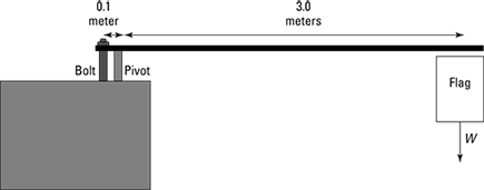
To find out how much force the bolt needs to provide, you start taking measurements and note that the flag has a mass of 50 kilograms — much more than the mass of the pole, so you can neglect that. The manager had previously hung the flag 3.0 meters from the pivot point, and the bolt is 10 centimeters from the pivot point. To get rotational equilibrium, you need to have zero net torque:
Στ = 0
In other words, if the torque due to the flag is τ1 and the torque due to the bolt is τ2, then the following is true:
0 = τ1 + τ2
What are the torques involved here? The direction of all the torque vectors is perpendicular to the plane of Figure 11-11, so consider only the component of these vectors in that direction (a positive component would correspond to a counterclockwise rotational force in Figure 11-11, and a negative component would correspond to a clockwise rotational force). Because you’re dealing with the components of the vector, which are numbers (not directions), I don’t write them in bold type. You know that the flag’s weight provides a torque τ1 around the pivot point, where
τ1 = mgl1
where m is the mass of the pole, g is the acceleration due to gravity, and l1 is the lever arm for the flag. Plugging in the numbers gives you the following:
τ1 = mgl1 = (50 kg)(9.8 m/s2)(–3.0 N) = –1,470 N·m
Note that this is a negative torque because the lever arm is negative — the force causes a clockwise turning force, as Figure 11-11 shows. (You can check this mathematically: The angle between the force and the lever is θ = –90°, so l = r sin θ = (3.0 m) sin –90° = –3.0 m.) What about the torque τ2 due to the bolt? As with any torque, you can write τ2 as
τ2 = F2l2
where F2 is the magnitude of the force at the bolt.
Plugging in as many numbers as you know gives you
τ2 = F2(0.10 m)
The lever arm is positive because the bolt provides a counterclockwise turning force (or mathematically, the angle between the force and the lever is θ = 90°, so l = r sin θ = (0.10 m) sin 90° = 0.10 m. Because you want rotational equilibrium, the following condition must hold:
Στ = τ1 + τ2 = 0
In other words, the torques must balance out, so
τ2 = –τ1 = 1,470 N·m
Now you can finally find F2, because you know both τ2 and l. Plug the known values into the equation τ2 = F2l2 and solve for F2:
τ2 = F2l2 = F2(0.10) = 1,470 N·m
Putting F2 on one side and solving the equation gives you
τ2 = F2l2
1,470 N·m = F2(0.10 m)
F2 = 14,700 N
The bolt needs to provide at least 14,700 newtons of force, or about 330 pounds.
Ladder safety: Introducing friction into rotational equilibrium
A hardware store owner has come to you for help with another problem. A clerk has climbed near the top of a ladder to hang a sign for the company’s upcoming sale. The owner doesn’t want the ladder to slip — lawsuits, he explains — so he asks you whether the ladder is going to fall.
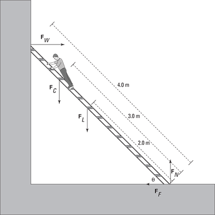
The situation appears in Figure 11-12. Here’s the question: Will the force of friction keep the ladder from moving if θ is 45° and the static coefficient of friction (see Chapter 6) with the floor is 0.7?
You have to work with net forces to determine the overall torque. Write down what you know (you can assume that the weight of the ladder is concentrated at its middle and that you can neglect the force of friction of the ladder against the wall because the wall is very smooth):
FW = Force exerted by the wall on the ladder
FC = Weight of the clerk = 450 N
FL = Weight of the ladder = 200 N
FF = Force of friction holding the ladder in place
FN = Normal force (see Chapter 5)
You need to determine the needed force of friction here, and you want the ladder to be in both linear and rotational equilibrium. Linear equilibrium tells you that the force exerted by the wall on the ladder, FW, must be the same as the force of friction in magnitude but opposite in direction, because those are the only two horizontal forces. Therefore, if you can find FW, you know what the force of friction, FF, needs to be.
Figure 11-12: Keeping a ladder upright requires friction and rotational equilibrium.
You know that the ladder is in rotational equilibrium, which means that
Στ = 0
To find FW, take a look at the torques around the bottom of the ladder, using that point as the pivot point. All the torques around the pivot point have to add up to zero. The direction of all the torque vectors is in the plane perpendicular to the one in Figure 11-12, so consider only the component of these vectors in that direction (a positive component would correspond to a counterclockwise rotational force in Figure 11-12, and a negative component would correspond to a clockwise rotational force). Because you’re dealing with the components of the vector, which are numbers, I don’t write them in bold type.
Here’s how to find the three torques around the bottom of the ladder:
Torque due to the force from the wall against the ladder: Here, r is the full length of the ladder:
FW (4.0 m) sin –45° = (–2.83 m)FW
Note that the torque due to the force from the wall is negative because it tends to produce a clockwise motion.
Torque due to the clerk’s weight: In this case, r is 3.0 meters, the distance from the bottom of the ladder to the clerk’s location:
FC (3.0 m) sin 45° = (450 N)(3.0 m) sin 45° ≈ 954 N·m
Torque due to the ladder’s weight: You can assume that the ladder’s weight is concentrated in the middle of the ladder, so r = 2.0 meters, half the total length of the ladder. Therefore, the torque due to the ladder’s weight is
FL (2.0 m) sin 45° = (200 N)(2.0 m) sin 45° ≈ 283 N·m
These last two torques are positive because the lever arms are positive, and therefore the forces generate a counterclockwise turning force, as Figure 11-12 shows.
Now, because Στ = 0, you get the following result when you add all the torques together:
Στ = 954 N·m + 283 N·m – (2.83 m)FW
0 = 1,237 N·m – (2.83 m)FW
(2.83 m)FW = 1,237 N·m
FW ≈ 437 N
The force the wall exerts on the ladder is 437 newtons, which is also equal to the frictional force of the bottom of the ladder on the floor, because FW and the frictional force are the only two horizontal forces in the whole system. Therefore,
FF = 437 N
You know the force of friction that you need. But how much friction do you actually have? The basic equation for friction (as outlined in Chapter 6) tells you that
FF actual = μsFN
where μs is the coefficient of static friction and FN is the normal force of the floor pushing up on the ladder, which must balance all the downward-pointing forces in this problem because of linear equilibrium. This means that
FN = WC + WL = 450 N + 200 N = 650 N
Plugging this into the equation for FF actual and using the value of μs, 0.700, gets you the following:
FF actual = μsFN = (0.700)(650) = 455 N
You need 437 newtons of force, and you actually have 455 newtons. Good news — the ladder isn’t going to slip.