CHAPTER THREE
TRACKWORK, WIRING AND SIGNALS
On occasions it is difficult to organize descriptions of layouts into a true and accurate chronology. Several of the constructional aspects overlap and in some cases aspects have to be covered slightly out of time, as it were – as will be apparent as this chapter unfolds. For instance, some lay all their trackwork first, then wire up and test, only to start the ballasting and scenic work after all that has taken place. In some ways, that is good practice, but it can be a slow process. That’s not to say that taking time is not good; quite the opposite. Too many layouts have been compromised by their builders being too hasty, either in the doing of it themselves or in commissioning work by others. No, the path for the impatient usually leads to failure. It’s just that, in the case of ‘Little Bytham’, I was most fortunate to have the services of Norman Solomon who made and laid the scenic side trackwork and also did some of its wiring-up. Norman’s technique is to lay any trackwork and ballast at the same time, leaving any wiring to be subsequently undertaken. It requires great skill and confidence, and his methods produce outstanding results, as, I hope, the following pictures show.
The ‘traditional’ method of ballasting – that of applying the ballast dry, brushing it into place, applying a wetting agent and dribbling on diluted PVA – was not employed. There are now devices that will spread the ballast for you as you go along from a kind of minihopper. Never having used such a device, I cannot comment but they seem to have merit. At no point was foam ballast underlay contemplated. Though this method is certainly quick, experience has taught me that, over time, it can degrade and disintegrate.
The track Norman employed was C&L plastic components and nickel-silver rail for the pointwork and SMP for the plain track. This is effectively Code 75 track. For those not capable of making their own track, Peco is the obvious choice and I employed that in the fiddle yard; for a few reasons – its excellence of manufacture, its ease of use and its robustness; the last mentioned being particularly important, and for that I used Code 100 where function took precedence over appearance. All the pointwork was modified to maintain its reliability, as will be seen in the step-by-step photographs.
I’ve included signalling in this chapter because it fits in naturally with the wiring, even though the signals were not fully installed and wired up until after much of the scenic work had been completed. As much as anything else, in fact, I believe it’s more important than many other aspects of a working model railway, fully functioning semaphore signals are essential for realistic operation. Too many layouts have non-working signals, often sited in the most unrealistic positions.
TRACKWORK, BALLASTING AND WIRING
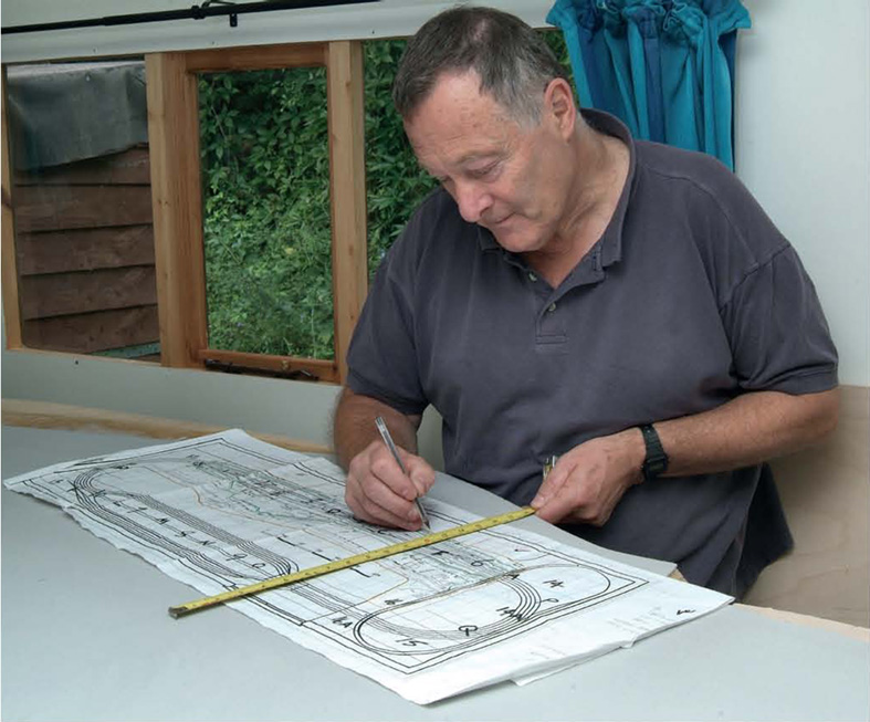
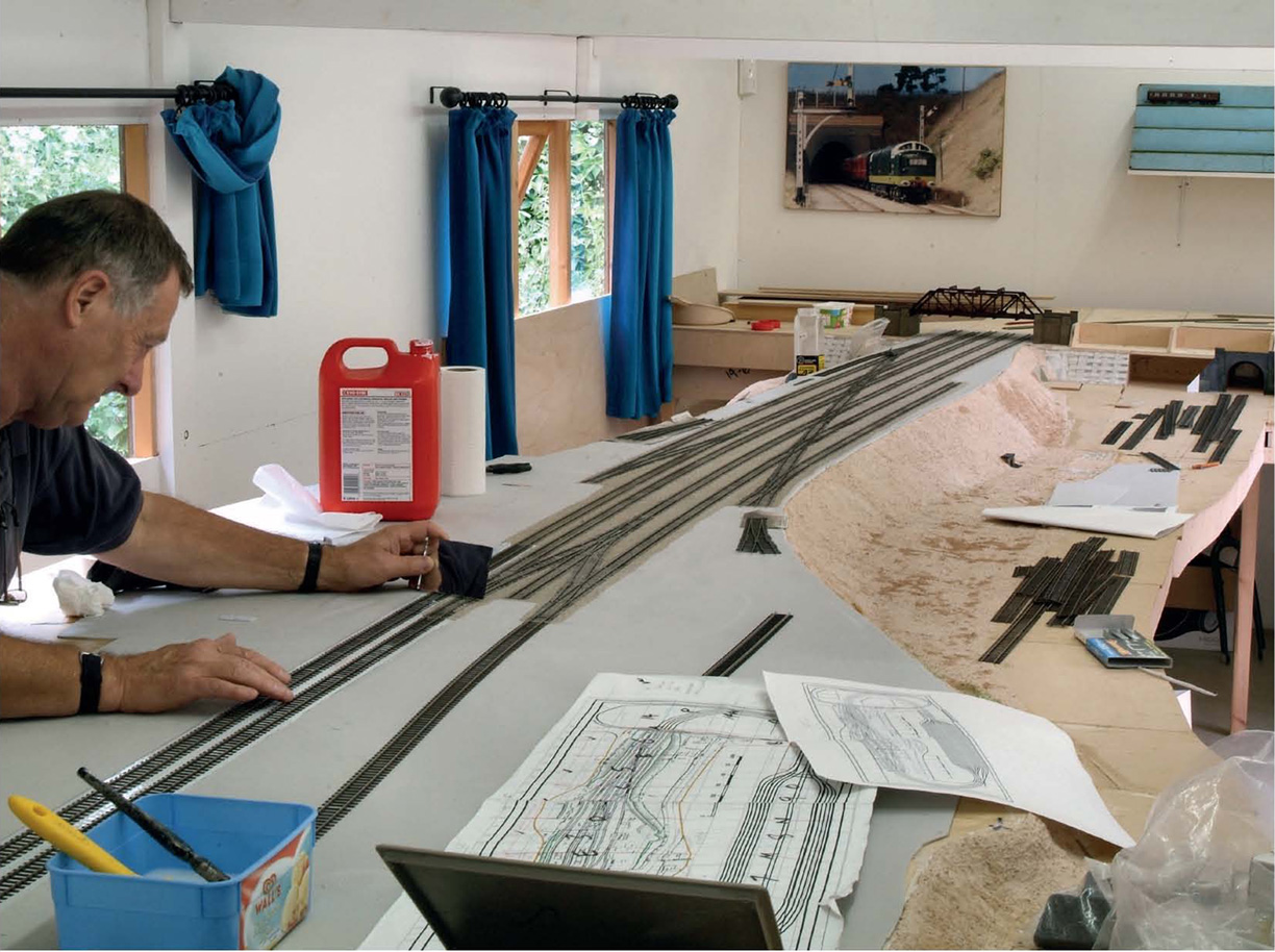
By modelling an actual prototype, all the decisions are made for you with regard to how many points there should be, where they should be positioned and how long any roads/sidings should be. Here, Norman is taking a datum from the scale plan to fix the first road’s position on the trackbed.
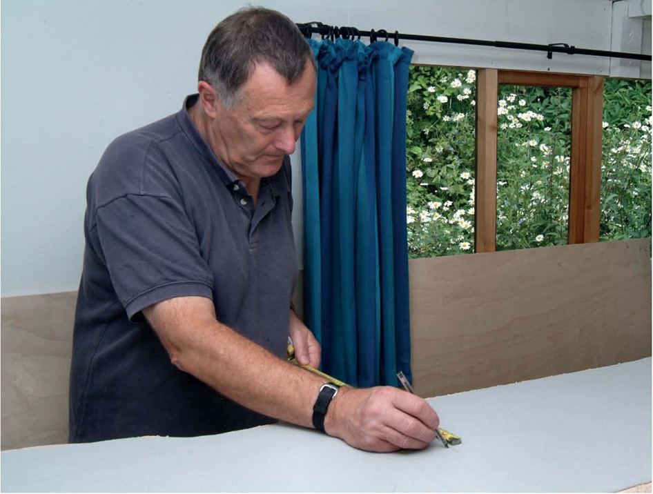
Having plotted the position, marks were made at regular intervals, giving the centre of the first road to be laid. As a base, insulation foam (which does not degrade) was stuck down to the plywood with PVA prior to this procedure taking place.
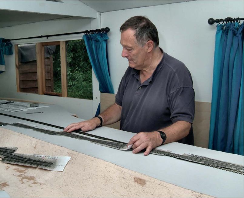
Norman had made the pointwork on top of paper templates, initially weathering them after they were completed. Once the first road had been positioned, any pointwork was temporarily laid in position as a trial fit. Such was the excellence of his work, no modifications were needed.
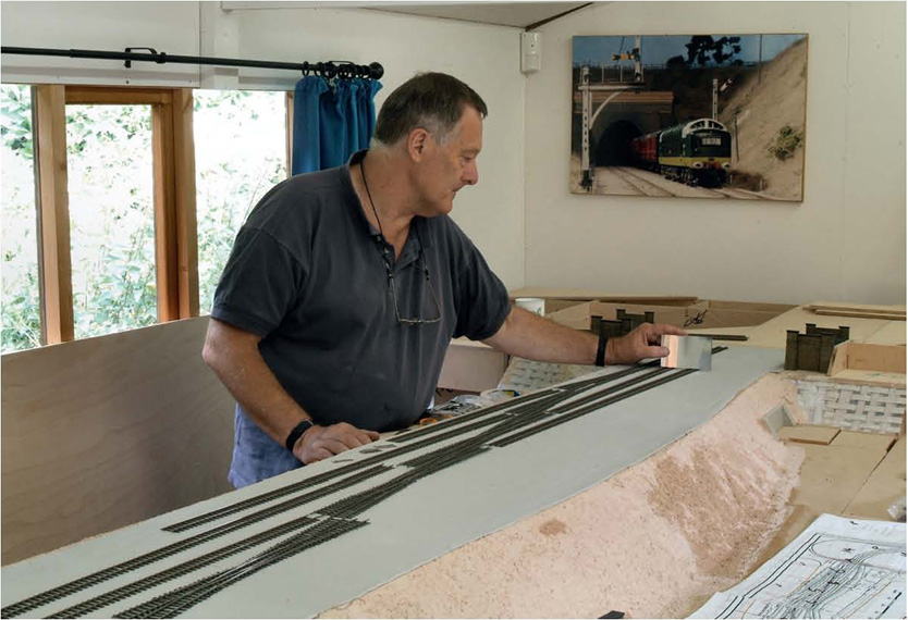
The main pointwork was the series of slips crossing between the respective slow lines at the north end. Complex formations like this must be right at source, otherwise running will be compromised. A small vanity mirror was used to ensure the alignment was correct at all times.
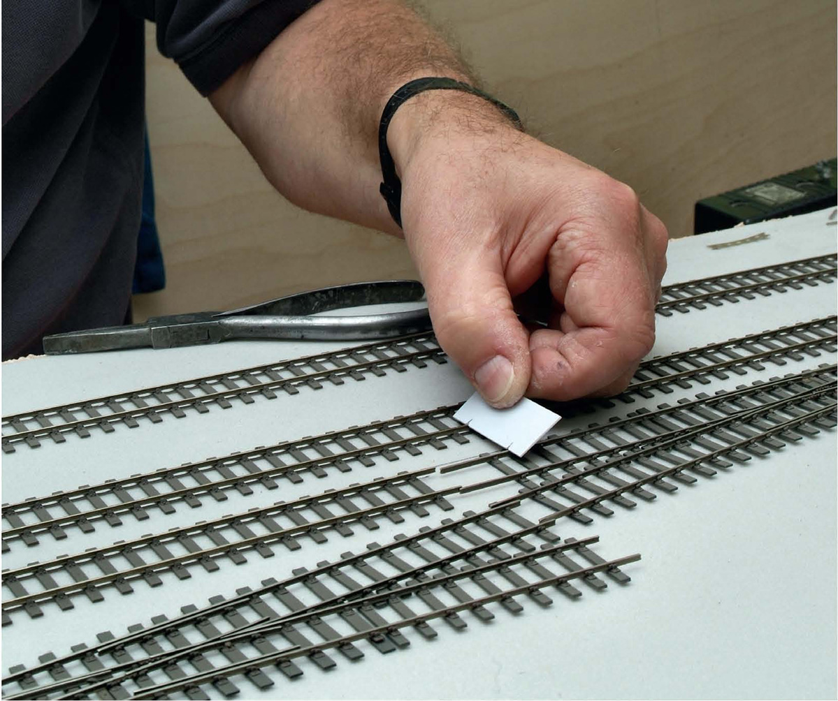
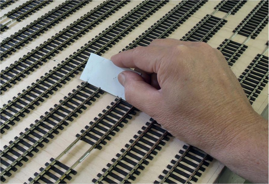
To maintain the correct centres (the six foot gap between adjacent running lines) a small Plastikard jig was used with two nicks cut into it, to fit over the respective rail heads of each line. Once the initial road’s position was marked out and confirmed, every subsequent road was plotted from this.
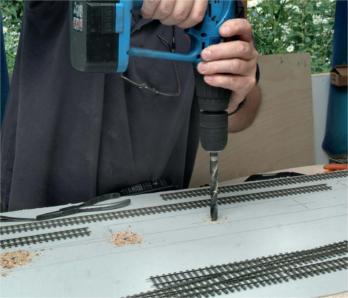
With the centres marked in pencil, the positions for point motor operating rods were marked and a hole drilled for each one.
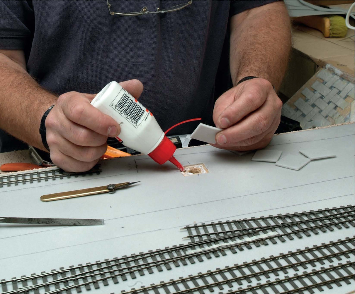
To cover the subsequent hole, a rectangular section was cut out around it and a replacement piece of foam fashioned, into which a slot was cut to allow the point operating rod to move from side to side, as appropriate. Without this, there’d have been a large hole underneath each tiebar.
Once happy with the alignment and with holes for the point rods made, a layer of high-quality PVA glue was spread over where the roads would be positioned.
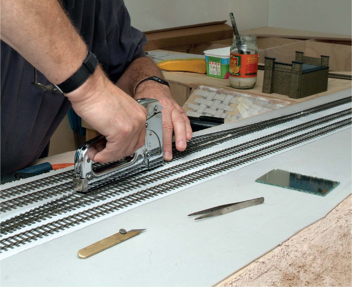
The trackwork was then laid in position and tacked down initially with a staple gun. Pinning track down on scenic sections is not advised.
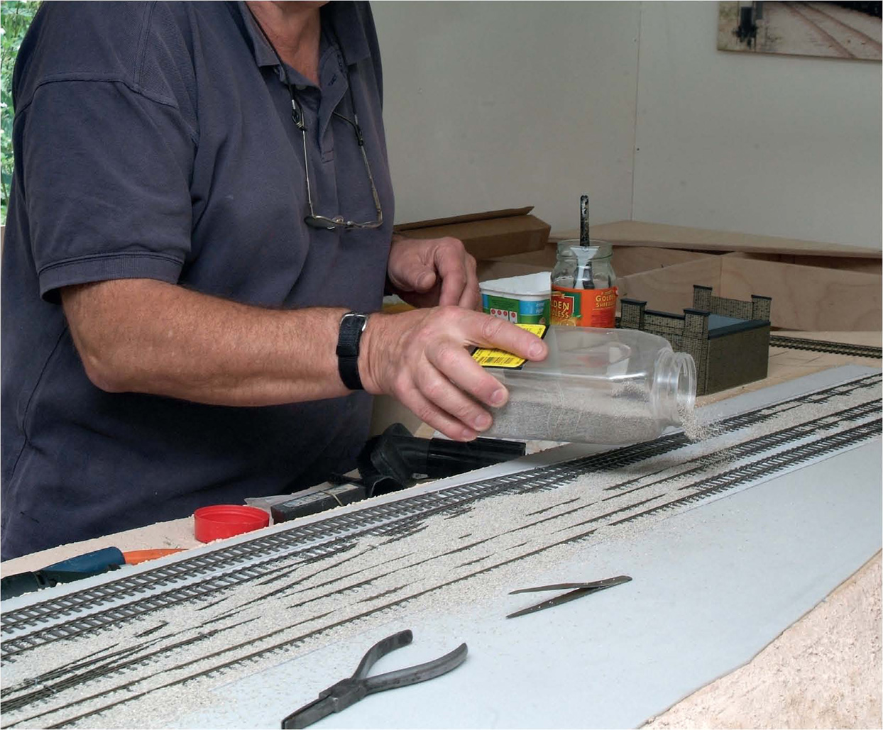
With the trackwork temporarily held in place with staples, the ballast was liberally spread over the rails and sleepers and on to the wet PVA. Slater’s N gauge granite ballast was used. Why OO gauge ballast is too big is not known, though it’s useful for ballasting O gauge track, and so on.
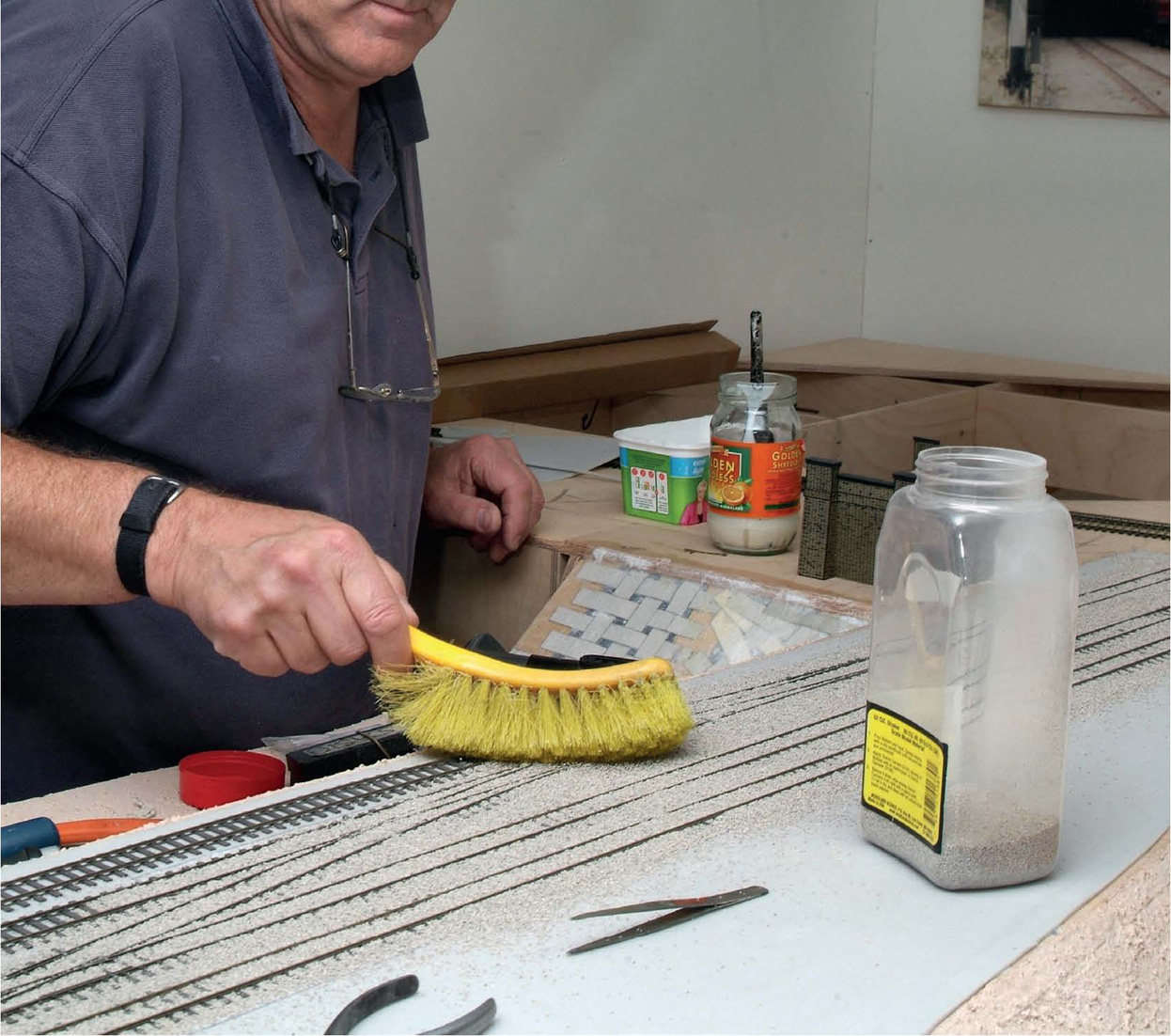
Surplus ballast was then levelled off with a cheap dust brush, ensuring an even layer overall.
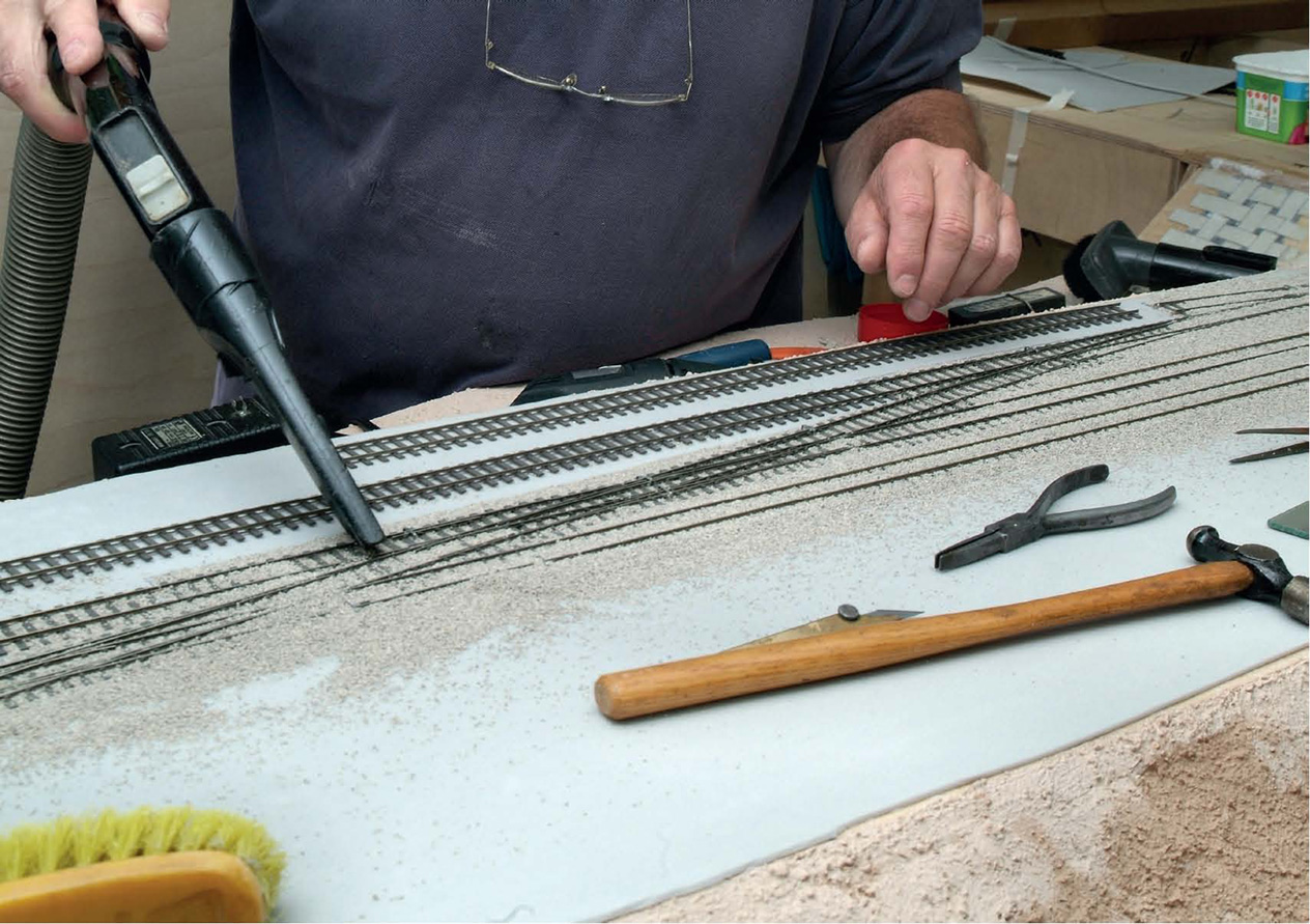
After checking again with the vanity mirror to ensure that all was well, loose ballast was taken off with a vacuum cleaner (after letting the ballast settle for about 15min). One can either have a dedicated vacuum cleaner (as here) or place a piece of nylon stocking over the nozzle so that any vacuumed-up ballast can be recovered. After this, any staples were removed.
With that long crossing in place and ballasted, further trackwork was added in the same manner, once more with the little mirror in place to check alignment.
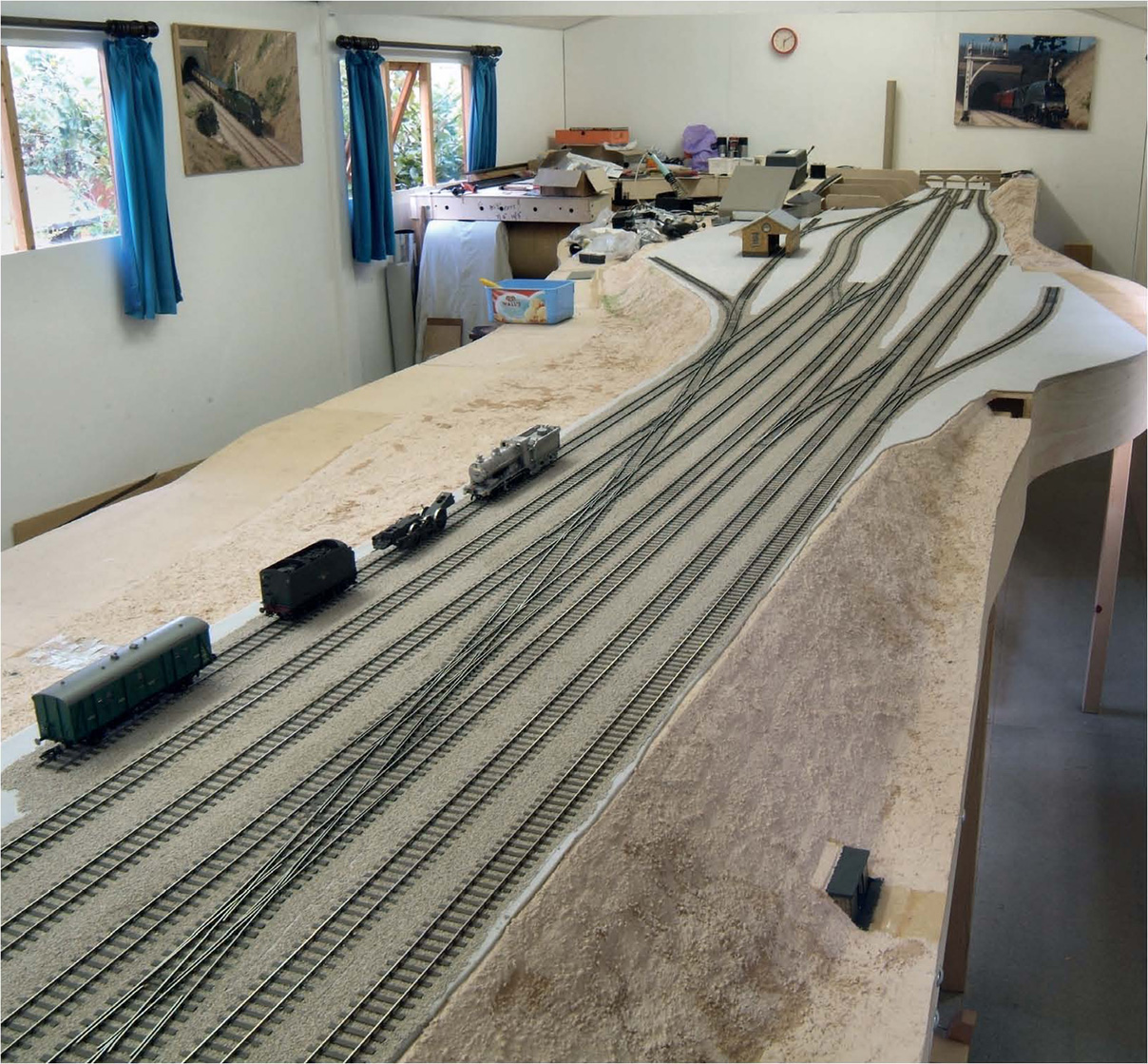
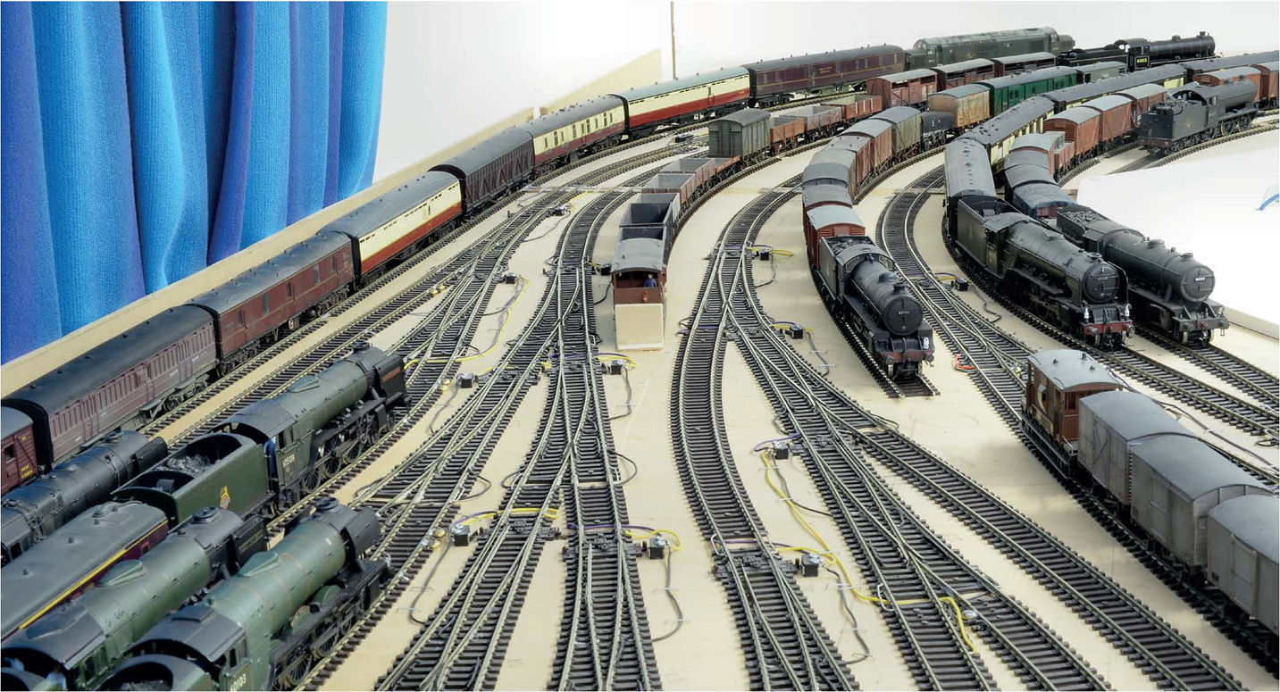
With all the trackwork down and ballasted, the generous sweep of the track formation through Little Bytham was apparent. Various vehicles (in the sidings) were used to check that running (via finger-power) was sound and true through any pointwork.
Because of my decision to use Peco Code 100 in the fiddle yard and out-of-sight sections of the railway, the two systems had to be made dead level where they joined. A thin sliver of cork proved exactly right for this purpose. Where models are required to go around sharp bends, extra clearances must be provided, otherwise adjacent trains will clip each other. You should always employ the longest vehicles in use to check for overhang (the Pullman car) or throw-over (a Thompson ‘Pacific’). A series of Tracksetta curves was most useful for ensuring smooth curves. The minimum radius on the out-of-sight/fiddle yard through-running sections was 36in (914mm). Less than this, for large locos, and the running can be compromised.
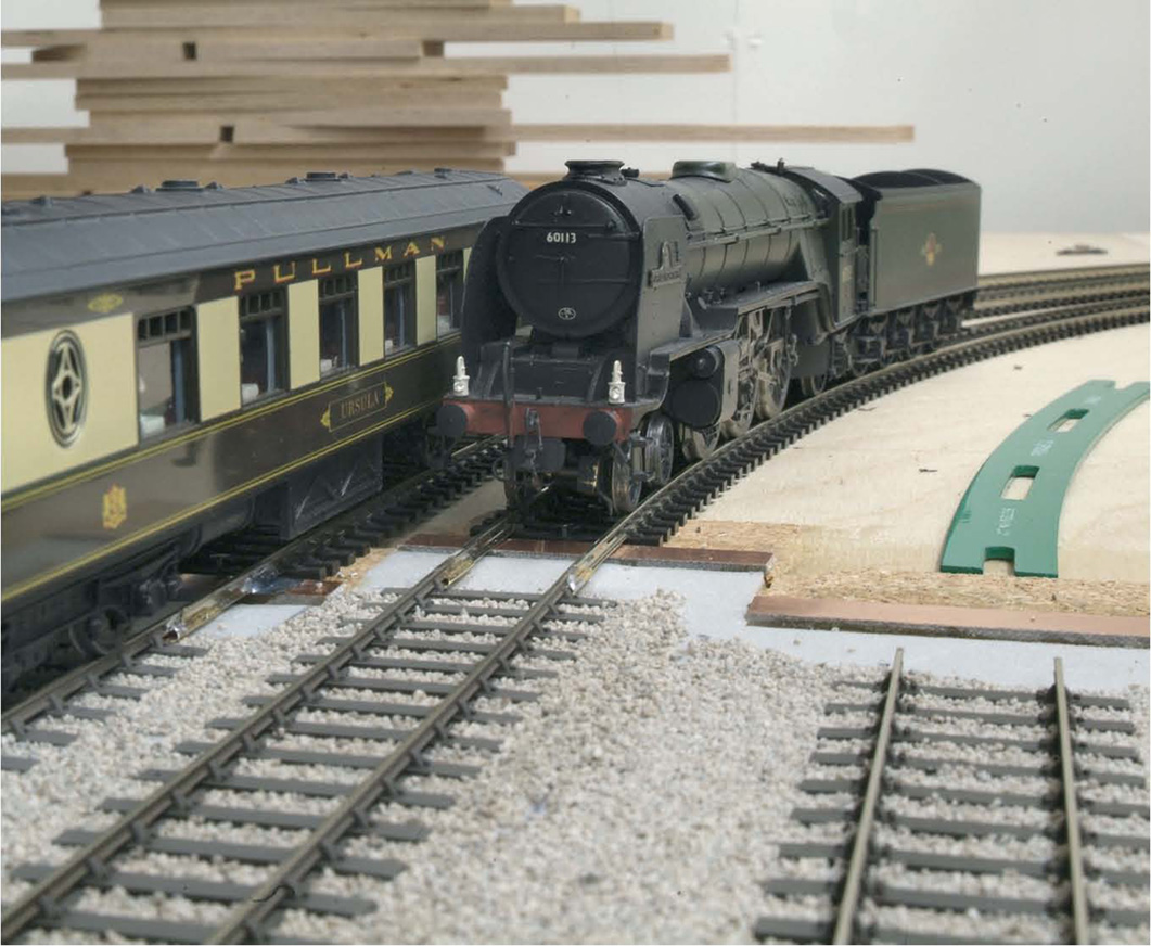
It was important that the transition between both trackwork systems was perfect, otherwise good running would have been compromised. I laid a transition curve on each fast line to ensure smooth passage, as can be seen beneath the girder bridge on the Down fast. Please note that any sharp curve was/is out of sight, so to speak. Main-line layouts are spoiled by going visibly on/off scene via right-angle bends. Not good.
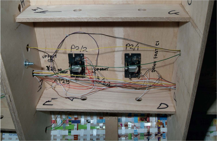
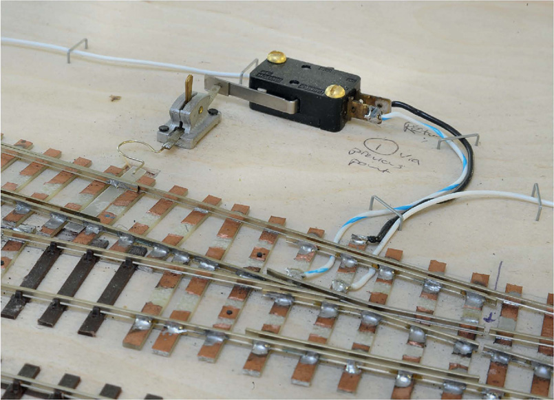
Fulgurex point motors were employed on the scenic sections for changing points. Here, two are shown in position, fully wired up. It would take a whole book to explain the function, fixing and wiring of point motors; suffice to say that the pairs of switches on the motor’s chassis were used for changing frog polarities and for linking in the workings of signals.
Piano wire was used for the physical operation of the tiebars. This had to be cut to length after installation very carefully with strong cutters. The little foam flag prevented it dropping right through whilst being installed.
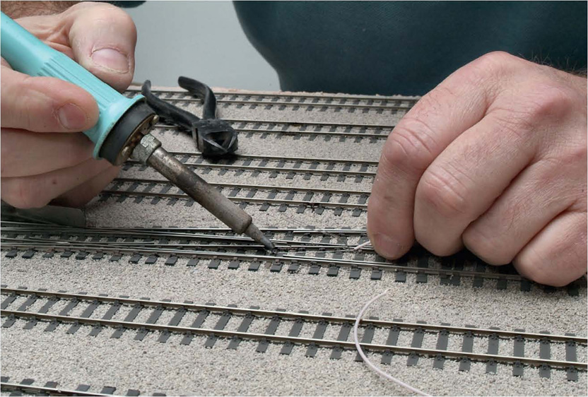
Any feeds to frogs and the like have to be discreet on scenic sections, so very fine insulated wire was employed, the ends being bared and pre-tinned. Away from frogs, every section of rail had a 5A piece of fusewire soldered to it, passing through a pre-drilled hole in the baseboard adjacent to the rail. These are called droppers and each one was connected to its correct bus-bar (mains section cable), laid along the whole layout. Common-return was employed, giving five separate bus-bars – common, then one for each outside rails of the respective Up and Down running roads.
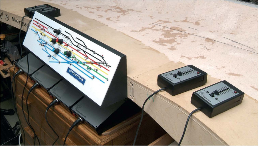
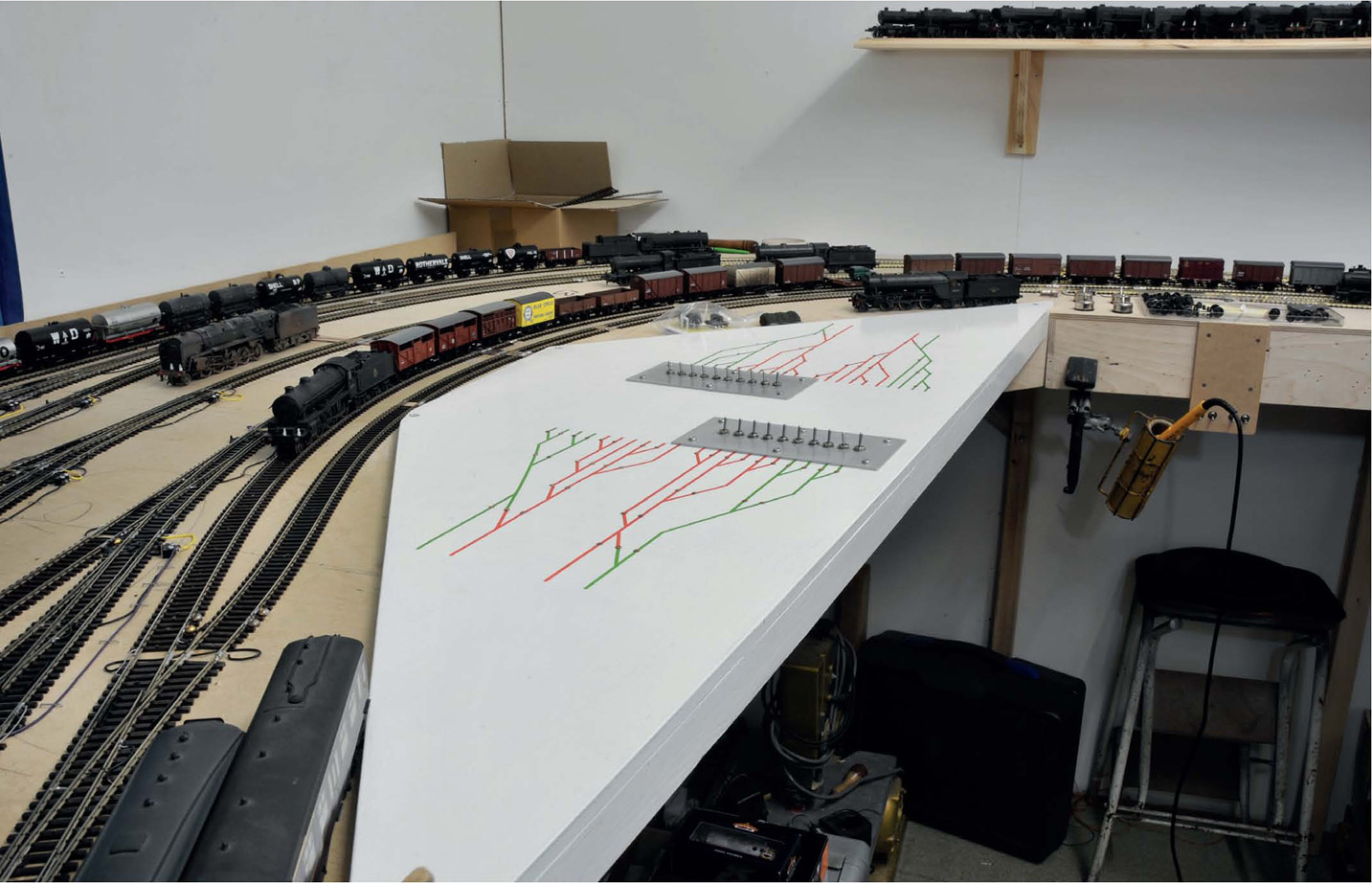
The scenic-side control panel was designed and made as a mimic of the track formation. Rotary switches provide full cab-control and four Helmsman transformers and controllers were employed to provide the power.
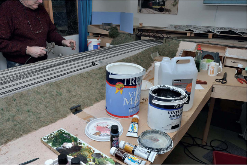
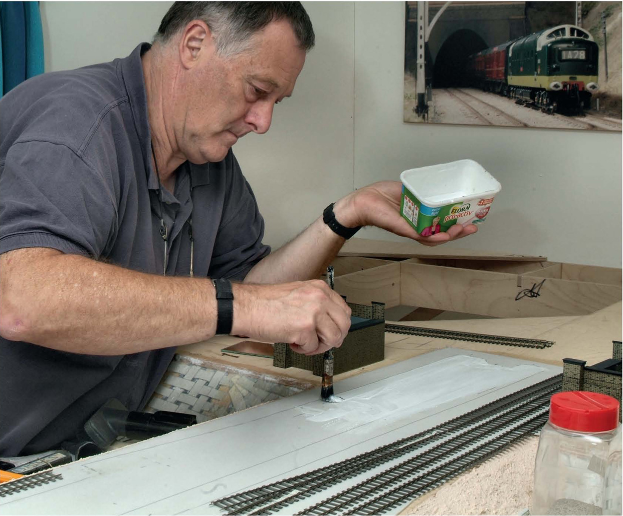
With all the scenic-side trackwork in place and wired-up, attention was turned to weathering it all. It had been pre-weathered with a dusting of paint through an airbrush. Final weathering is a very subtle business and observations of real trackwork are essential. An airbrush was employed to give uniformity to the whole formation using diluted household emulsion paint and acrylics, mixed to suit.
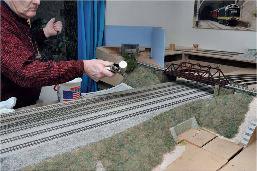
Broad sweeps were used, with great care being taken not to flood the carefully ballasted track.
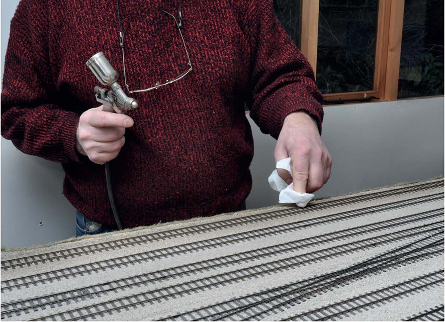
After every sweep, the railheads were carefully cleaned. Though emulsion/ acrylic paint is not as robust as enamels or cellulose, leaving it to dry on railheads is not a good idea.
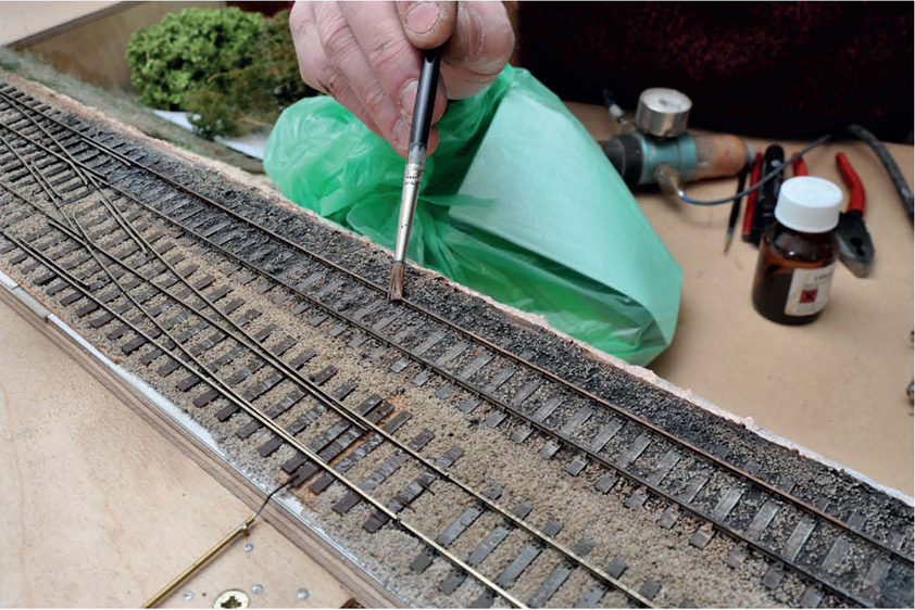
Where any trackwork was little-used or disused (as here on the M&GNR section), a sable was used for applying thicker weathering. Neat acrylics were employed for this purpose.

Norman Solomon’s method of making, laying, ballasting and weathering trackwork is perfectly illustrated in this view of a finished section.
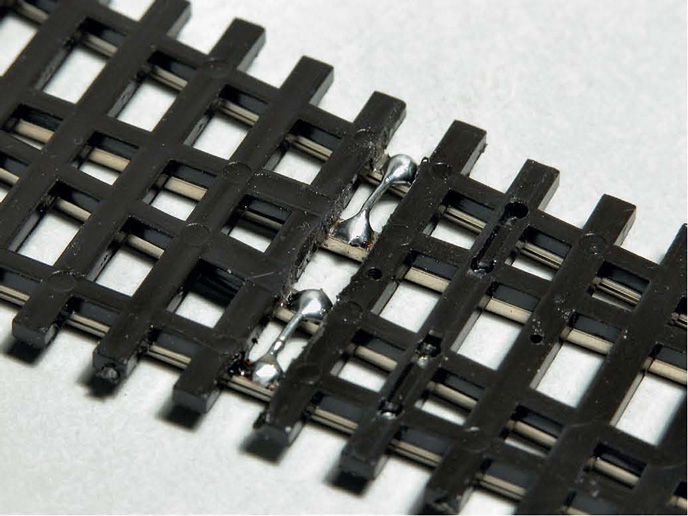
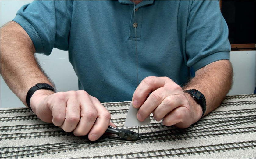
As mentioned, I employed Peco Streamline Code 100 for the fiddle yard. As supplied, the switch-rails and stock-rails are not permanently bonded, relying on friction-contact to pass electricity. It is a case of ‘when’ rather than ‘if’ this system will fail. I cut off part of the sleeper webbing and soldered-in sections of 30A fusewire.
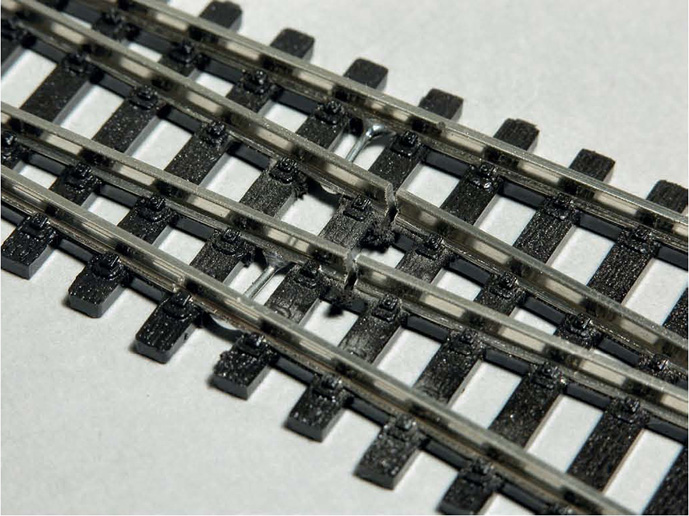
Because the above will give an immediate short circuit at the live frog (never use Insulfrog points), I then gapped the frog from the switch rails by cutting through the latter with a slitting disc in a mini-drill. This isolated the frog, necessitating a subsequent feed.
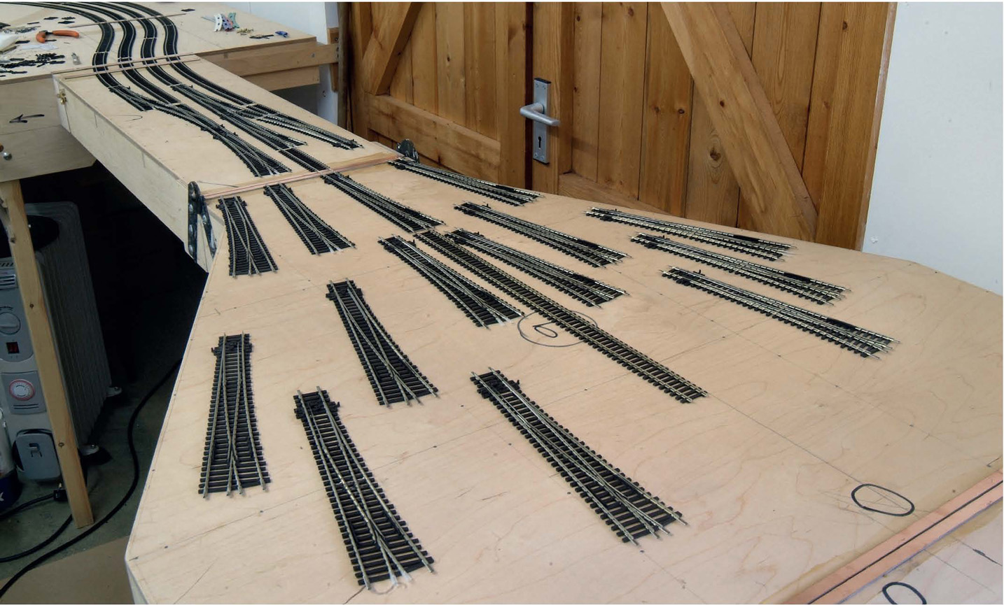
In order to get the very best of running, I adopted a ‘swan-neck’ arrangement to get on/off the fiddle yard from the 180-degree curves leading to the scenic section. This increased the radius, making it different from the initial plan. Large-radius points were used almost exclusively, and I laid them out initially to give me an idea of where to fit them.
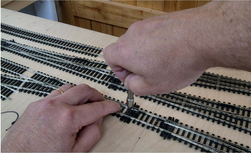
Once happy with their positions, the points were temporarily pinned-down and a pilot hole drilled through the baseboard using the hole in the point tiebar as a guide.
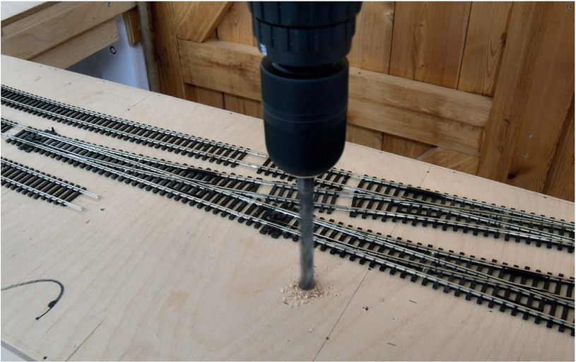
The points were then removed and a larger hole for the operating rod was drilled through the baseboard using a power drill, with the pilot hole as a guide.
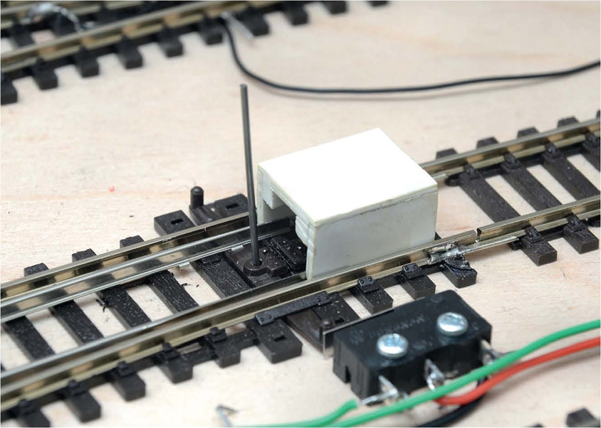
Seep point motors were used in the fiddle yard, fired through a CDU. A friend made this device out of Plastikard; it ensured that the point blades were centralized when securing the point motor operating rod from beneath – better as a two-man job. When happy, the rod was cut off to length again, very carefully, with strong cutters.
Because I’d isolated the frogs by cutting through the switch rails to the frog, the frog had then to be fed and switched. I used microswitches for this purpose, activated by the extension to the point’s tiebar and surfacemounted for convenience.
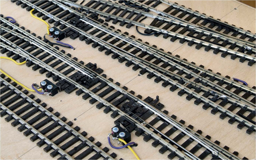
The installation of the Seep point motors was very simple: just two screws fixing them to the underneath of the baseboards. These screws were not tightened right up, giving a little flexibility to the operation. Tightening them up too much can cause the solenoid to bind. Chocolate-block connectors were used to provide feeds, but only in the fiddle yard. All scenic-side feeds/connections were soldered.
As with the scenic-side trackwork, correct spacing of adjacent roads was achieved using a simple plastic jig, with slots at the correct distances to take the railheads. All tracks in the fiddle yard were pinned down and all sections of rail fed either from droppers linked together underneath or a surface-mounted wire loop soldered between two sections of rail, bypassing the fishplate. Never rely on fishplates for passing electrical current.

Once wiring-up was completed, initial test trains were run. The north end entrance/exit to the fiddle yard is shown here, running across the lifting section. Please note how great care has been taken to ensure the maximum radius of passage for trains, resisting the temptation of using small-radius points to get more in and lengthen roads. Too many layouts, in my experience, have been compromised by attempting to cram too much in.
The south end of the fiddle yard showing, once more, the notion of ‘swan-necks’ for easing the passage of trains. This view also shows the kick-back sidings, employed to give extra trains. These are accessed by either reversing out or reversing in; both types are shown here.
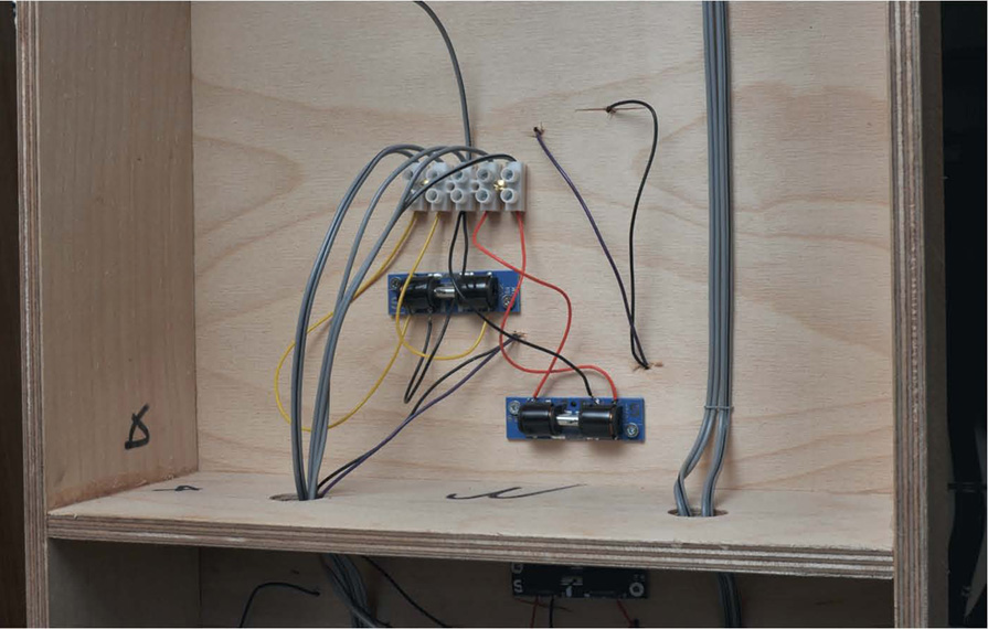
A robust control panel was made to operate the fiddle yard, pointwork being thrown by applying the end of an electric pencil to an appropriate stud, the pencil being fed by the CDU. Simple on/off switches control the feeds to each road. (I do not use DCC, but that is another story.)
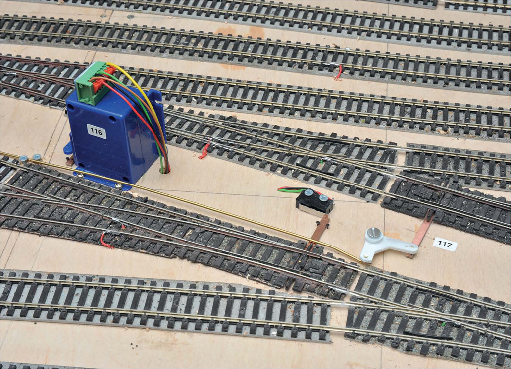
Other types of point motors are available other than Fulgurex. Tortoise are an excellent slow-acting type, as are Cobalt, the latter shown here surface-mounted, operating points via rods and cranks. Surface-mounting such units, though easier to install, means more surface space in the fiddle yards is taken up by their installation. This is part of the fiddle yard on Peterborough North.

The standard from years ago for point motors was the venerable H&M type. These can still be obtained second-hand, but it’s wise to fit separate microswitches rather than use the H&M contacts. I’ve also found this so for Seep and Peco solenoids, where they contain their own switching mechanisms. The point motors shown here control the points on Retford’s fiddle yard.
Changing points does not have to always be a complicated electrical process. Old-fashioned GEM mechanical levers are just as adequate where access is easy, and they can operate the microswitch as well. This one is in use on Geoff Kent’s latest EM layout.
SIGNALS
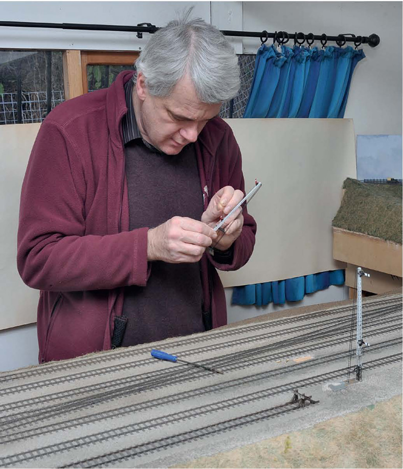
As previously mentioned, I’ve been very lucky in having dear friends do a lot of work in the making of ‘Little Bytham’, mainly through the principle of bartering. In this shot Graham Nicholas is preparing to install one of the co-acting signals, in this case one built by Mick Nicholson.
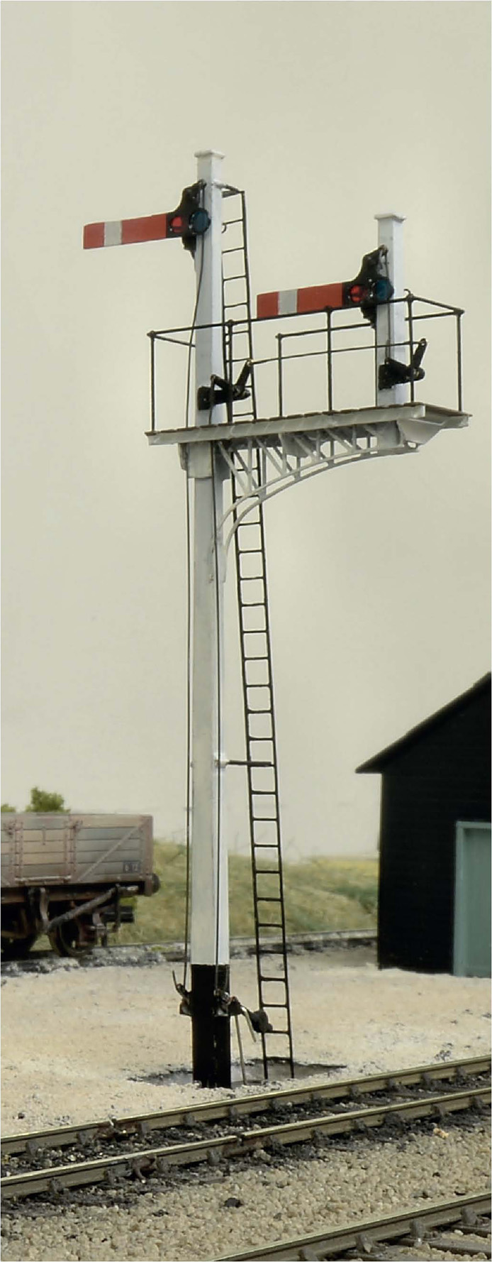
Graham also made some of the signals, including this handsome bracket controlling the Down slow straight on or Down slow to Down fast. It was made from scratch and MSE components.
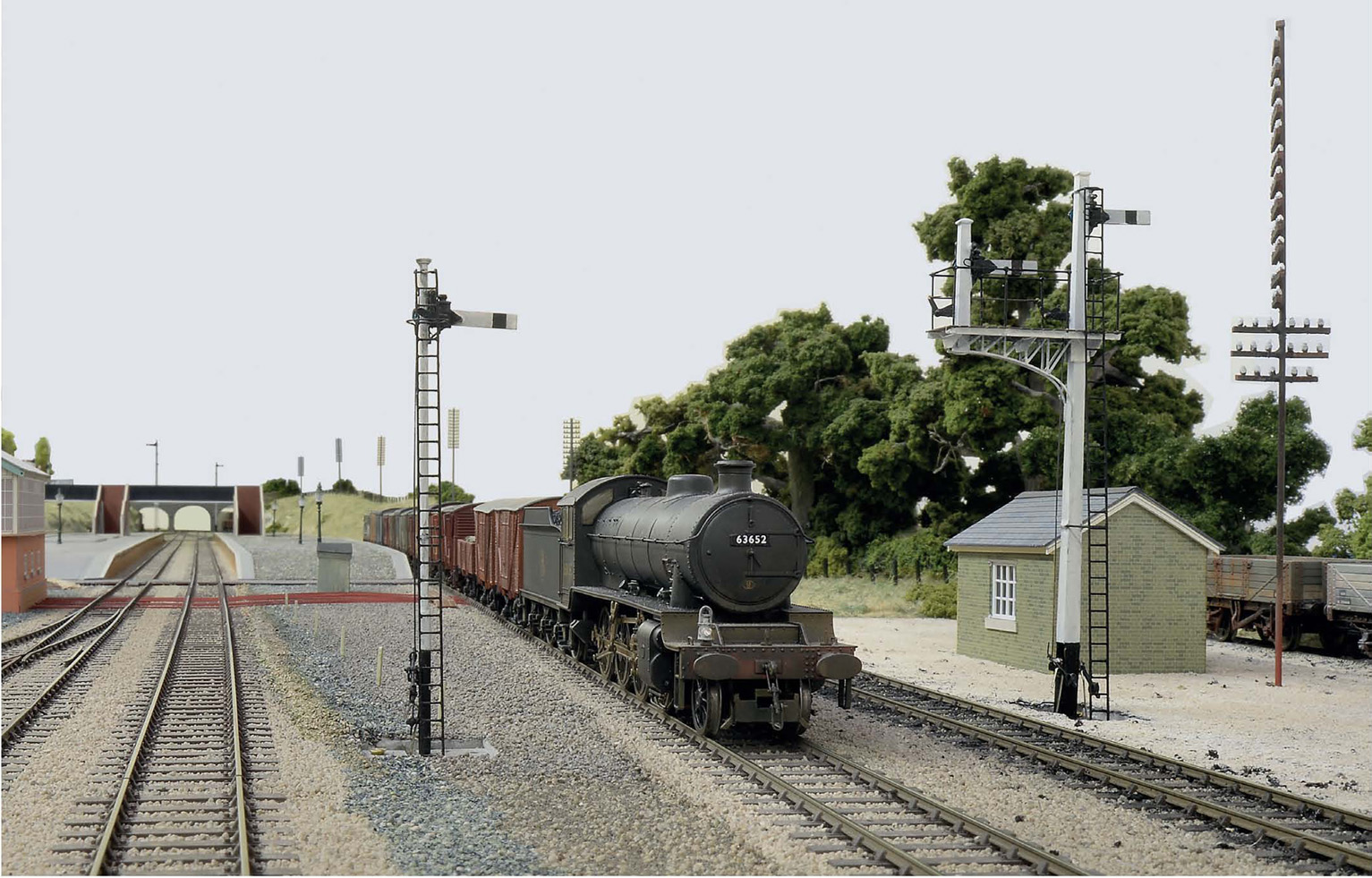
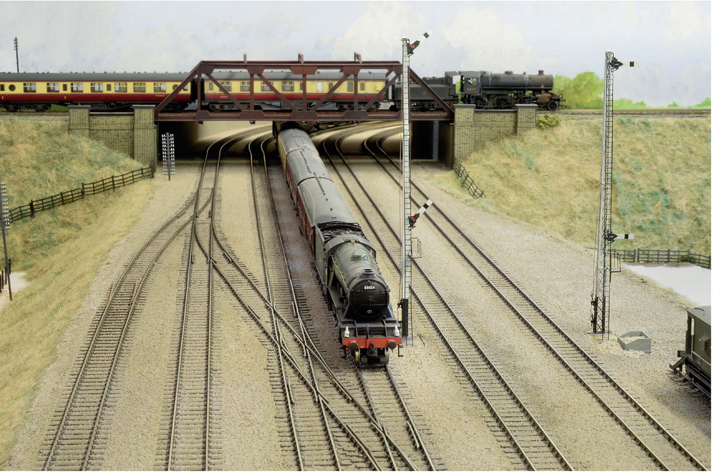
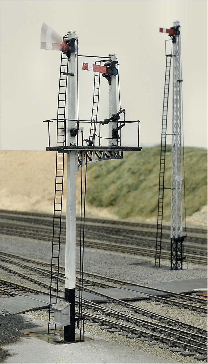
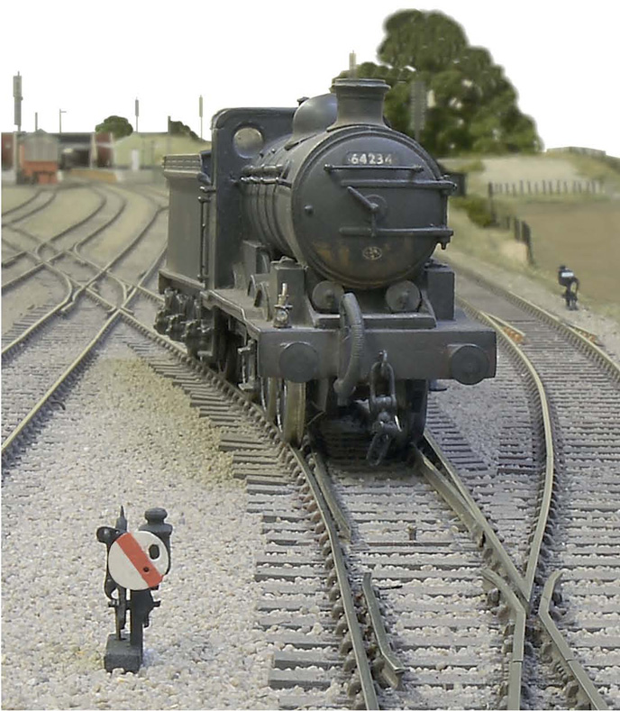
In partnership with its Down fast neighbour, the splitting signal is ‘on’ against a modified Hornby O1. The driver has stopped at the limit for the signal and this view illustrates how following an actual prototype is so much better with regard to realism. The splitting signal is sited one track away from the road it controls, adjacent to a layby. This was obviously because of site restrictions, but who would have arranged it like that on a freelance model? Note the pulley posts leading to the Down fast signal; these were made from brass square section of the appropriate size. If made of plastic, they’d be wiped out in track cleaning.
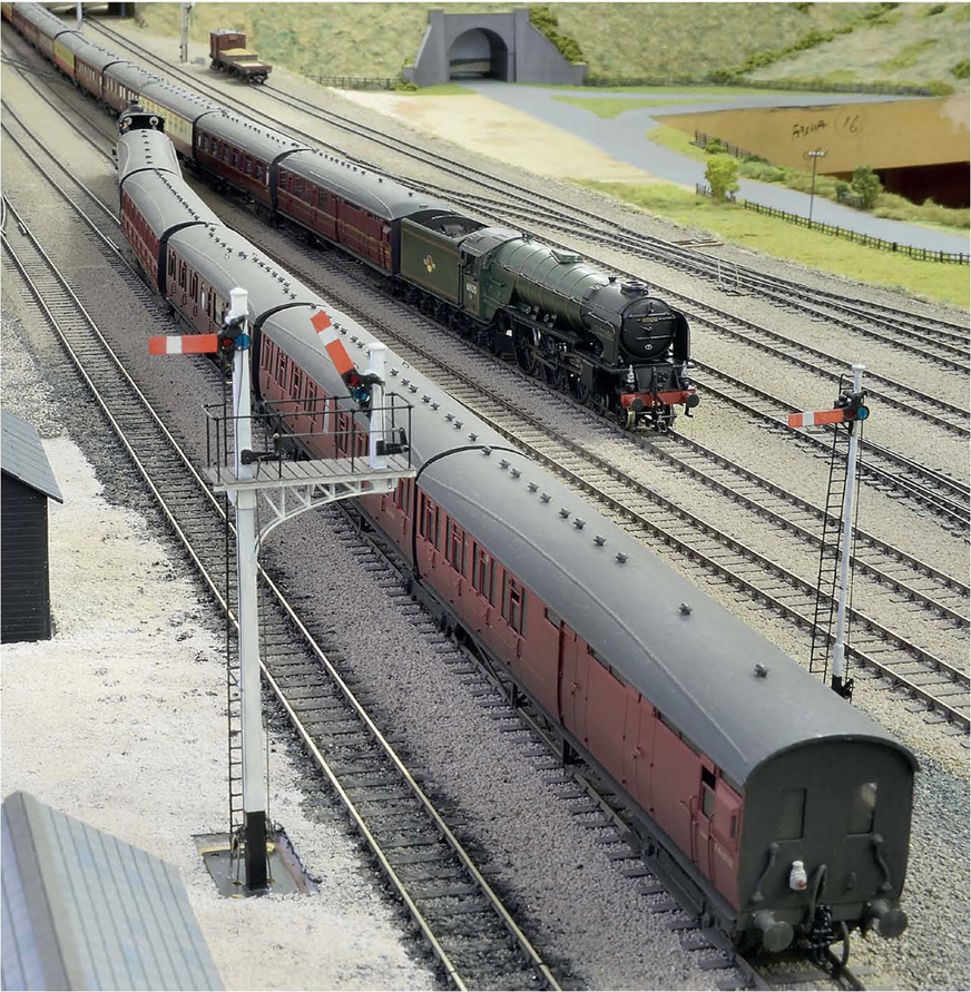
The signal in use; this time allowing a stopper to proceed from the Down slow to the Down fast. By using the switches on the Fulgurex point motor’s chassis, the correct board is raised for the route set.
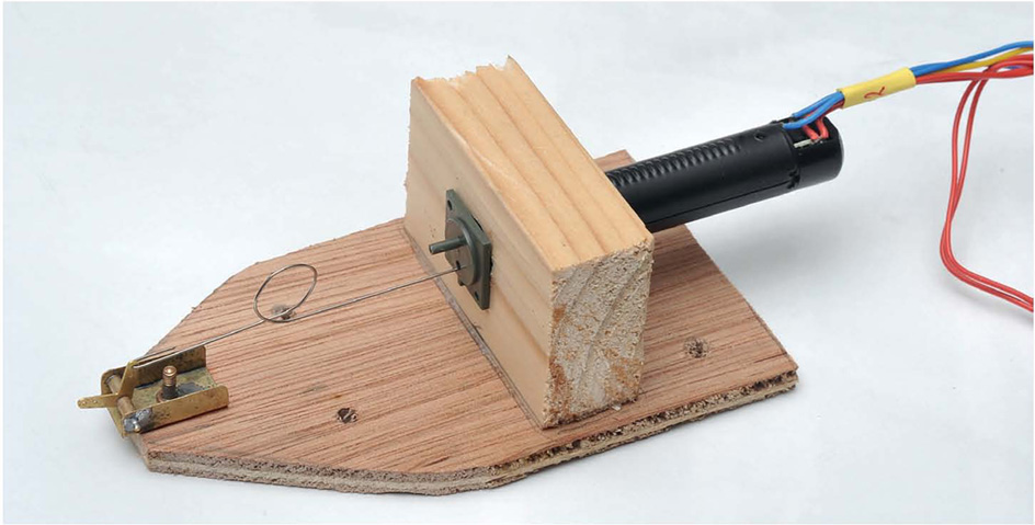
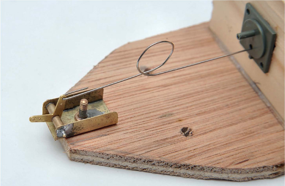
Weissman dampened solenoid motors were used to operate the signals, fixed to blocks of wood and operated via a simple right-angle crank. The circle in the wire gives adjustment.
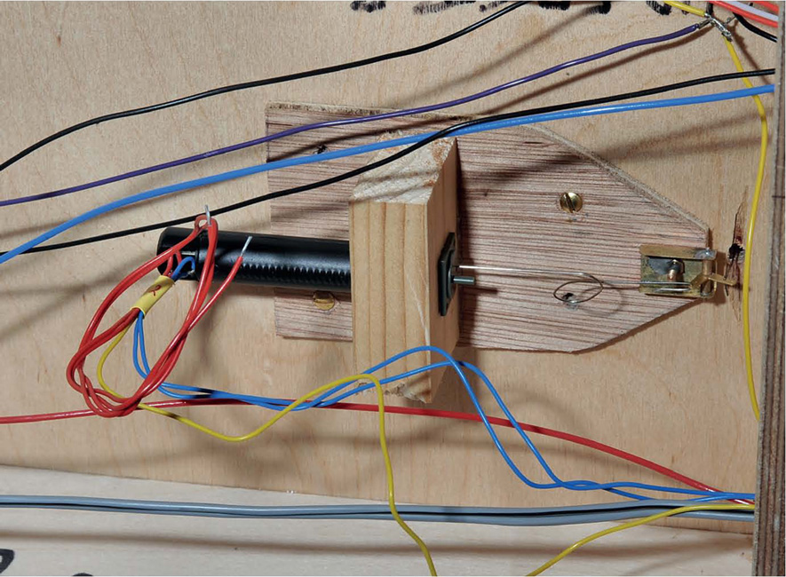
The operating mechanism screwed underneath the baseboard. These motors operate off a 12V supply.
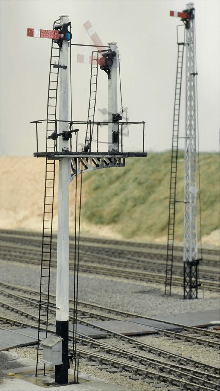
The Up slow straight on or Up slow to Up fast is shown here, with the respective signals in operation. The motion is slow for pulling ‘off’ and the return to ‘on’ is quicker, but there is no bounce.
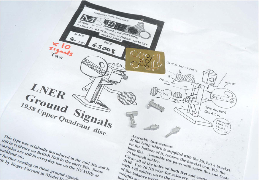
There were several ground signals at Little Bytham. Originally it was my intention to just make these as dummies, from MSE components.
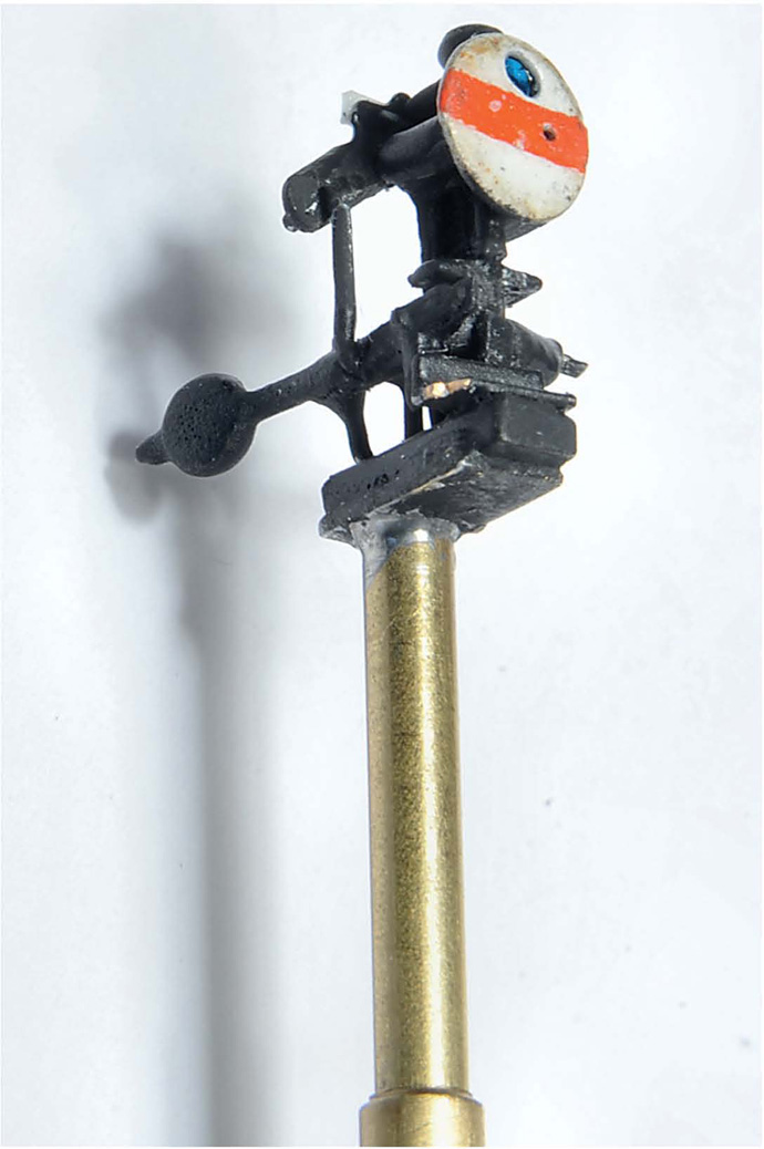
Good friend Roy Vinter would have none of this and decided to make them all work. He fixed the working signal to a length of brass tube.
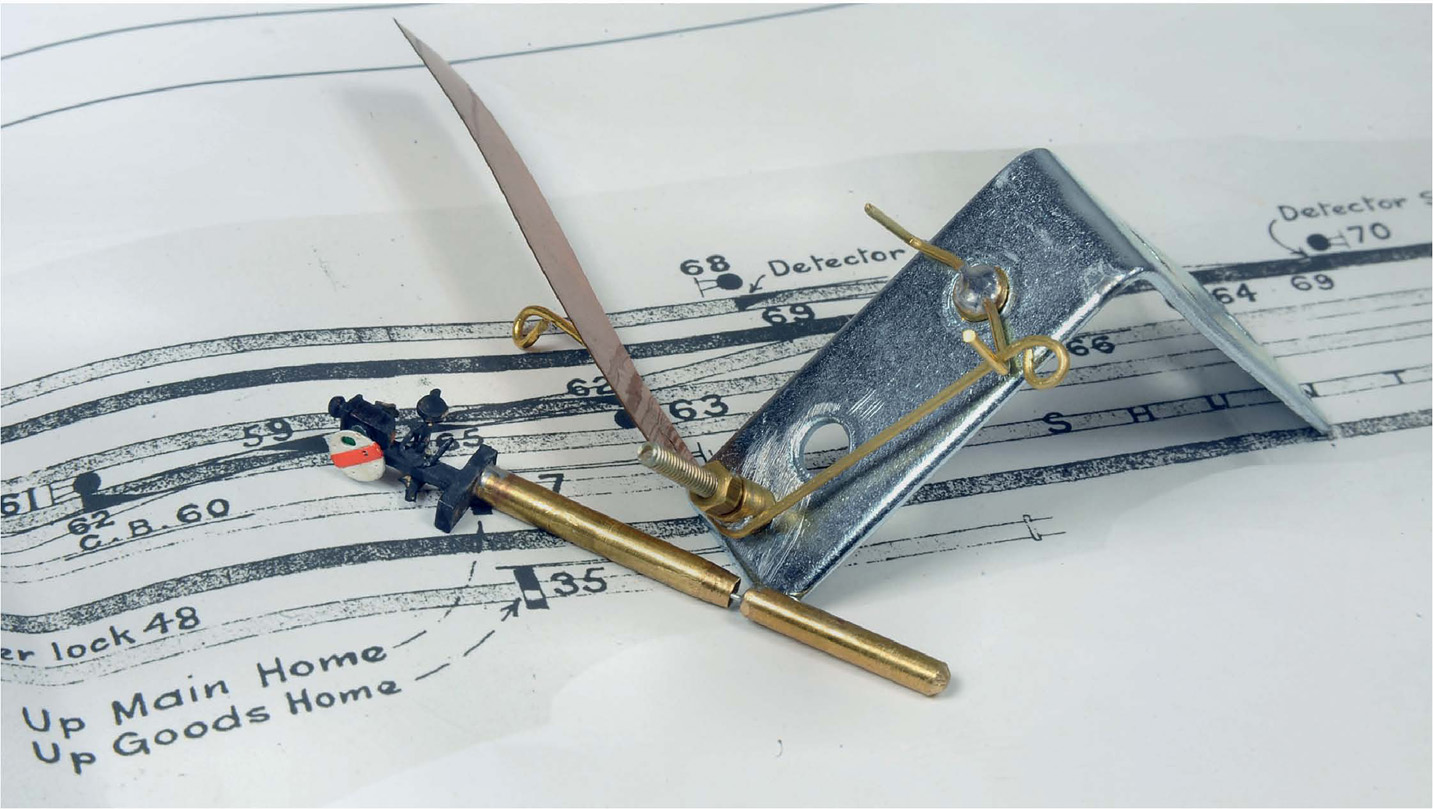
Through and beneath this tube, suspended by a thin wire attached to the signal’s counter-balance, he installed a solid brass ‘pendulum’ weight. He also made a simple bracket and paddle to operate this.
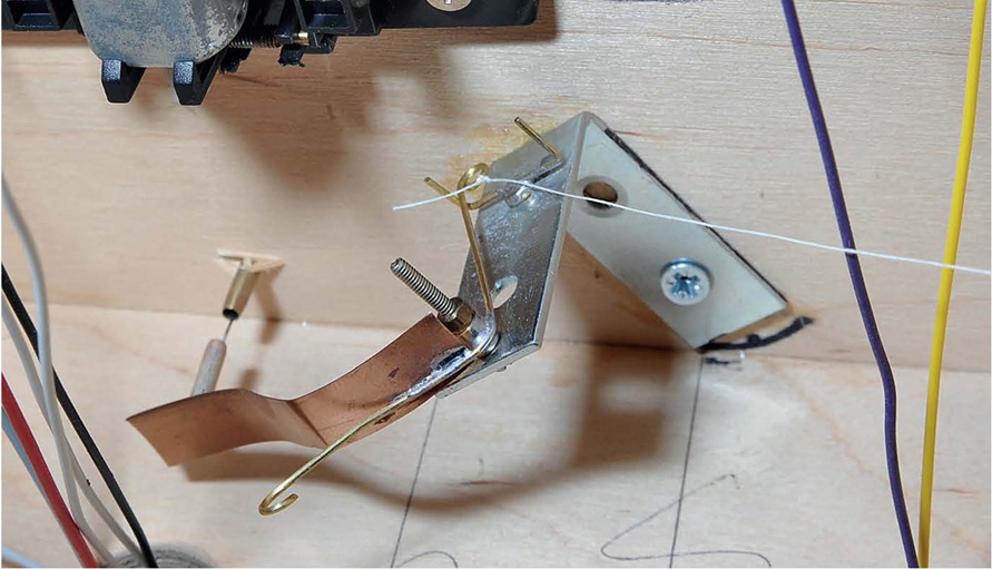
With each bracket screwed to the underneath of the baseboard, the paddle was adjusted to press up on to the signal’s pendulum to pull it ‘off’, cotton being used for this purpose, attached via two pieces of steel rod to a little lever at the baseboard’s edge. When the lever is moved to put the signal ‘on’ again, gravity (via the pendulum) returns the signal to ‘on’.
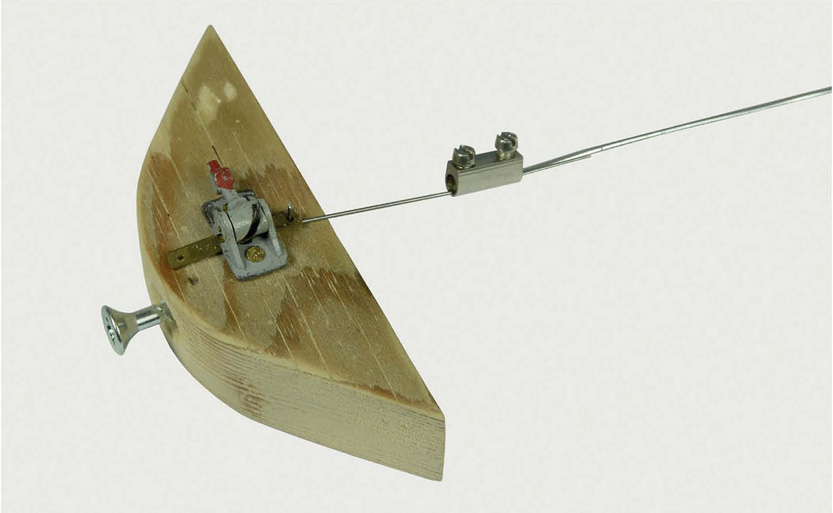
To operate Roy’s little signals from the baseboard edge, another good friend, Ray Chessum, came up with this simple idea. The steel rod (supported underneath the baseboard by little eyelets) attached to the cotton at one end was fixed at its other end to the screw-together pieces taken out of chocolate-block connectors, giving plenty of adjustment. Piano wire from the GEM lever was also fixed into the screw-together bits, after it was passed through a hole in the baseboard edge.
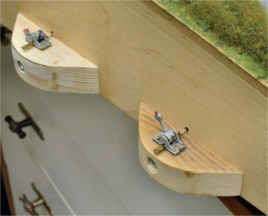
Fixed to the baseboard edge like this, with the blocks of wood rounded off to prevent damage to either themselves or bellies passing by, the levers are on the baseboard edge as near to the signals they control as possible. If nothing else, it means the operators get exercise!
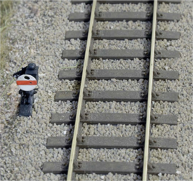
In situ these little dollies really look the part. Their operation has added greatly to the realism on ‘Little Bytham’.
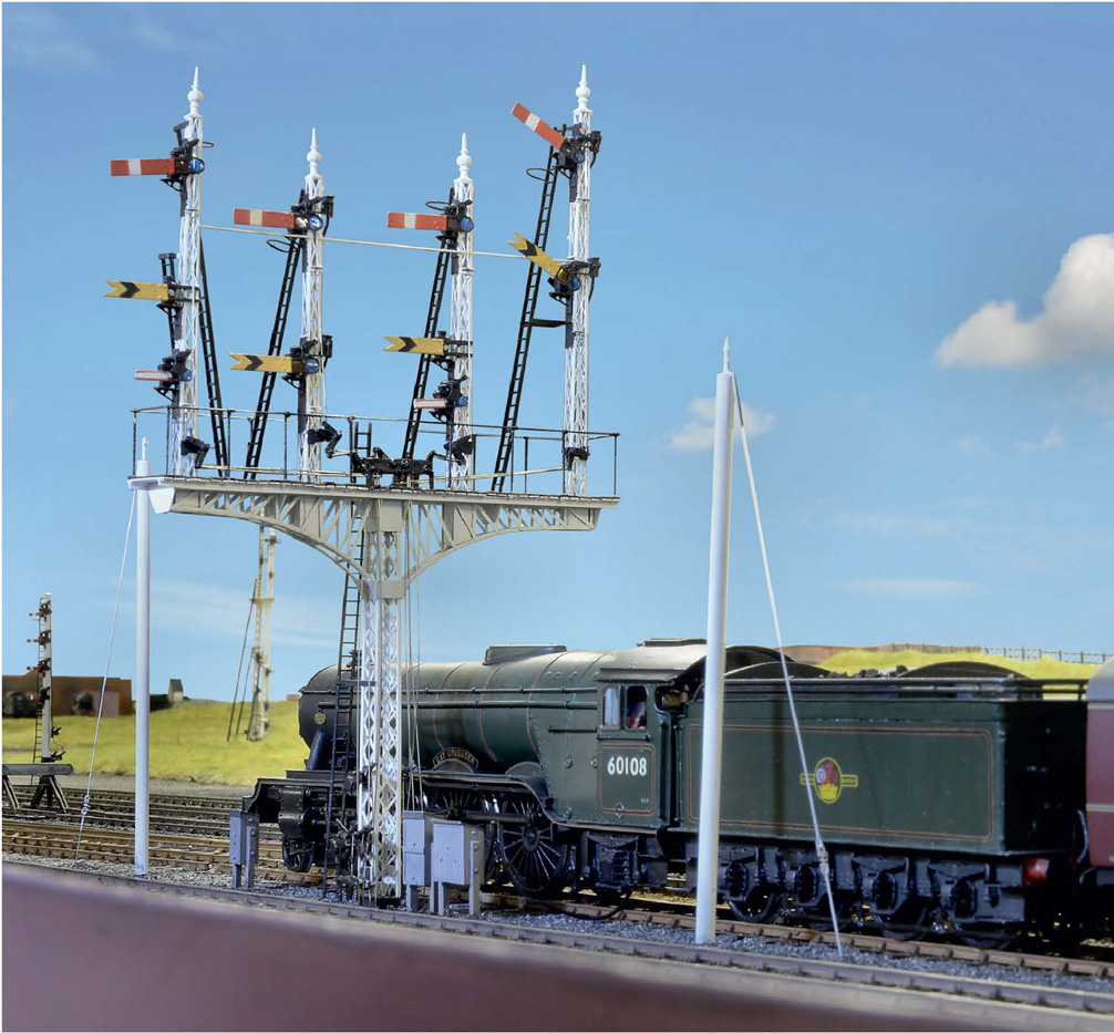
Though I admit to being a partisan in this matter, no finer semaphore signals were as impressive as those built for the GNR, LNER or the Eastern, NER or Scottish Regions of BR. Right from the early days of the GNR, the signalling engineer (one French of name) insisted on sky backgrounds for his semaphores to help drivers sight them. Many were supported on delicate lattice posts (to reduce wind resistance). A fine example of these signals in miniature was built by Fredrick Hunt for use on ‘Retford’.
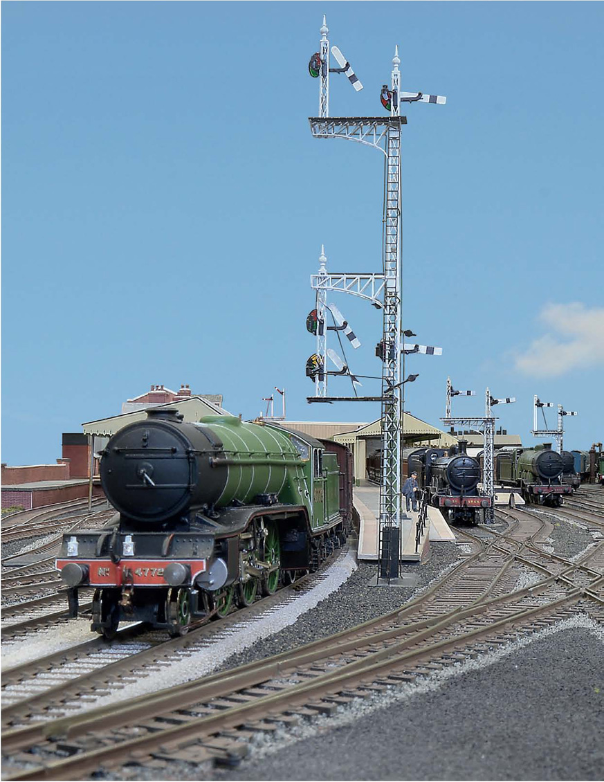
Another stupendous example of an even taller GNR/LNER lattice post signal was built by Graham Nicholas for his ‘Grantham’ layout – a somersault lattice, too.
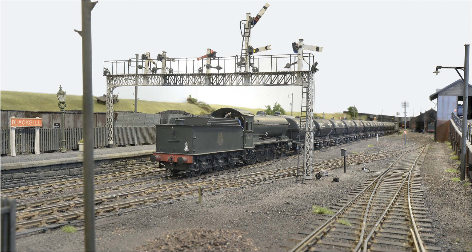
Eddy Ford’s ‘Black Gill’ has been featured already and, when it comes to signalling, it is a perfect example for showing how complex mechanical signalling can be. This gantry has both BR upper-quadrant arms and the original slotted NER lower-quadrant types. They all work, too.