FIG 6:1 Section through the fivespeed gearbox
6:1 Description
6:2 Removing and refitting gearbox
6:3 Dismantling and reassembling gearbox
6:4 The gearchange mechanism
6:5 Fault diagnosis
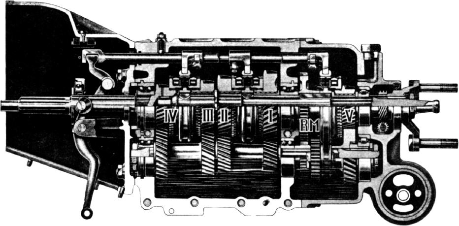
Models in the Giulia, 1750 and 2000 ranges are provided with gearboxes having five forward speeds and reverse, synchromesh operating on all five forward gears. FIG 6:1 shows a section through the five-speed gearbox. Gear selection is by means of either a floor-mounted lever or a steering column lever and linkage, both of which are covered in Section 6:4. The light-alloy gearbox case consists of two main casing halves, a front bellhousing which encloses the clutch assembly, and a rear cover. An exploded view of the gearbox case assembly is shown in FIG 6:2. Gearbox oil level should be maintained to the level of the filler plug, and should be checked and, if necessary, topped-up to the correct level at 4000 mile intervals. Every 10,000 miles the gearbox should be drained while the oil is hot, then refilled with fresh SAE.90 gear oil.
1 On cars equipped with floor-mounted gearlevers, remove the floor carpet, slacken the clamp and remove the rubber boot from the gearlever. Unscrew and remove the gearlever, collecting the two balls from the inside of the gearlever.
2 Refer to FIGS 6:3 and 6:4 and detach the following items from beneath the car. The propeller shaft at the intermediate joint flange 1, marking both flanges for correct refitting; the propeller shaft centre bearing support 2, the cross-plate 3, speedometer drive cable 4, exhaust pipe bracket 5, clutch cover 6, gear selector lever 7, reversing light leads 8, clutch operating lever 9 and the gear engagement lever 10.
3 Remove the bolts shown in FIG 6:5 securing the gearbox crossmember to the car body, then remove the bolt securing the gearbox to the crossmember as shown in FIG 6:6 and remove the crossmember. Remove the bolts securing the gearbox to the engine crankcase and remove the gearbox towards the rear. Do not allow the weight of the gearbox to rest on the splined shaft during removal, or serious damage to the clutch driven plate will result. Drain the oil from the gearbox and remove the front section of the propeller shaft from the rear of the gearbox, using tool A.2.0124.
Refitting the gearbox is a reversal of the removal procedure, noting the following points. Index the alignment marks at the intermediate joint flange when refitting the propeller shaft. If the clutch was removed, refer to Chapter 5 for clutch driven plate alignment procedure. Support the gearbox when refitting to the engine to avoid straining the clutch driven plate. Refill the gearbox with oil.
FIG 6:1 Section through the fivespeed gearbox

FIG 6:2 Exploded view of gearbox casing
Key to Fig 6:2
1 Washer
2 Stud
3 Dowel
4 Bolt
5 Stud
6 Bolt
7 Dowel
8 Stud
9 Inspection cover
10 Clutch housing
11 Stud
12 Bush
13 Washer
14 Nut
15 Stud
16 Stud
17 Nut
18 Washer
19 Bottom cover
20 Washer
21 Nut
22 Cover plate
23 Rubber cap
24 Self tapping screw
25 Nut
26 Gasket
27 Gasket
28 Magnetic drain plug
29 Closing plug
30 Gearbox casing halves
31 Nut
32 Vent plug
33 Rear cover
34 Stud
35 Gasket
36 Pin
37 Speedometer pinion
38 Pinion housing
39 Washer
40 Nut
41 Speedometer cable
42 Rubber banded mounting
43 Sealing washer
44 Washer
45 Nut
46 Washer
47 Bolt
48 Washer
49 Cross member
50 Washer
51 Gearbox assembly
52 Screw
53 Reversing lamp switch
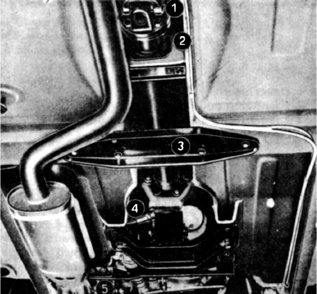
FIG 6:3 Items to be detached for gearbox removal
1 Mount the gearbox in a suitable stand. Refer to FIG 6:7 and remove the gearbox drive flange, screwing in one of the flange bolts as shown to prevent the mainshaft from turning. Unscrew the nuts securing the rear cover and remove the cover, noting that for floor-change gearboxes it will be necessary to engage third gear to do this.
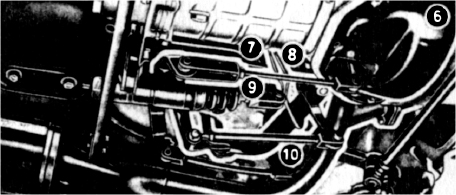
FIG 6:4 Items to be detached for gearbox removal
2 Refer to FIG 6:8 and remove the bolt securing the fifth and reverse gear selector fork in order to remove the selector shaft. Remove the reversing light switch, if fitted. Detach the spring clips and remove the clutch release bearing from the clutch release lever. Remove the nut arrowed in FIG 6:9 and remove the gearchange lever. Using suitable circlip pliers, remove the retaining ring shown in FIG 6:10 from the groove in the shaft. Remove the large retaining ring which secures the seat for the reverse gear return spring from the groove in the boss. Remove the spring seat and withdraw the shaft.
3 Unscrew the nuts securing the gearbox bellhousing to the gearbox case and remove the bellhousing. Unscrew the nuts fastening the gearbox case halves together and separate the halves as shown in FIG 6:11, tapping the case lightly with a soft mallet if necessary. Do not try to lever the case halves apart or the joint faces will be damaged. The joint faces are machined to fit together without gaskets so care must be used to avoid damage to any gearbox joint face during servicing.
4 Remove the selector shaft plunger retaining plate as shown in FIG 6:12 and withdraw the plungers, springs and balls. Loosen the setscrews shown in FIG 6:13 which lock the selector forks to the selector shafts, then slide out the shafts and forks together with the interlock. If only one of the selector shafts is to be removed, push out the shaft with a dummy shaft as shown in FIG 6:14 to hold the interlock plunger and ball in position. Push the dummy shaft out with the selector shaft when refitting. If necessary, remove the outer race of the layshaft rear bearing with puller A.3.0101. The race should be refitted with a suitable punch and the aid of a press. FIG 6:15 shows the method of removal.
5 Lift the constant pinion shaft and mainshaft from the gearbox case and separate the two shafts. Lift out the layshaft assembly. Remove the reverse idler gear from the upper gearbox case half. FIG 6:16 shows the mainshaft and constant pinion shaft assemblies.
The dismantling of the internal parts of the gearbox is best carried out with access to suitable press equipment. If such equipment is not available, a suitable puller can be employed to remove the various components from their shafts. FIGS 6:16 and 6:17 show the components of the mainshaft and constant pinion shaft assemblies.
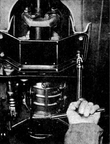
FIG 6:5 Removing the crossmember mounting bolts

FIG 6:6 Removing the gearbox to crossmember bolt
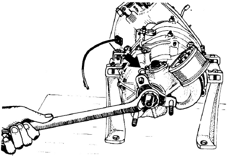
FIG 6:7 Removing the gearbox drive flange

FIG 6:8 Removing the fifth and reverse gear selector bolt
1 With the press plates behind reverse gear, press off the reverse gear together with the synchronizer unit, fifth-speed gear and the rear bearing. Remove the securing keys.
2 Press off the intermediate bearing and withdraw the shims, the first-speed gearwheel with its bush, and the operating sleeve for the first- and second-speed synchronizer unit. Press off the synchronizer hub for first and second gears then remove the keys and slide off the second-speed gearwheel.

FIG 6:9 Removing the gearchange lever
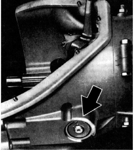
FIG 6:10 The reverse gearshaft retaining rings

FIG 6:11 Separating the gearbox case halves

FIG 6:12 Removing the selector shaft plunger retaining plate

FIG 6:13 The selector fork setscrews

FIG 6:14 Inserting a dummy shaft for the removal of one selector shaft
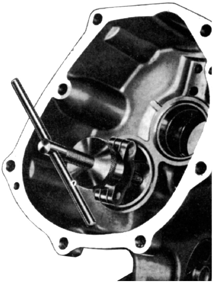
FIG 6:15 Removing the layshaft rear bearing outer race
3 Remove the retaining ring from the third- and fourth-speed synchromesh hub then press off the hub. Slide off the third-speed gear and remove the keys.
After removing the retaining ring and the shim beneath it, press off the constant pinion shaft bearing,
The dismantling of the layshaft is only necessary if one or more of the layshaft bearings are to be renewed (see FIG 6:18).

FIG 6:16 The mainshaft and constant pinion shaft assembly

FIG 6:17 Components of the mainshaft and constant pinion shaft assemblies
Key to Fig 6:17
1 Retaining ring
2 Synchronizing ring
3 Locking band
4 Stop
5 Roller bearing
6 Segment
7 Constant pinion shaft
8 Bearing
9 Shim
10 Retaining ring
11 Spacer
12 Oil seal
13 Synchronizing ring
14 Stop
15 Locking band
16 Second-speed gearwheel
17 Mainshaft
18 Key
19 Third-speed gearwheel
20 Locking band
21 Stop
22 Synchronizing band
23 Segment
24 Retaining ring
25 Bushes
26 Operating sleeve
27 Synchromesh hub
28 Shim
29 Retaining ring
30 Retaining key
31 Gearwheel
32 Bearing
33 Shim
34 Spacer bush
35 First-speed gearwheel
36 Stop
37 Locking band
38 Bush
39 Segment
40 Synchronizing ring
41 Retaining ring
42 Operating sleeve
43 Synchromesh hub
44 Retaining ring
45 Segment
46 Bolt
47 Drive flange
48 Nut
49 Lockplate
50 Oil seal
51 Speedometer drive gear
52 Bearing
53 Shim
54 Fifth-speed gearwheel
55 Bush
56 Spacer bush
57 Stop
58 Locking band
59 Segment
60 Synchronizing ring
61 Retaining ring
62 Operating sleeve
63 Synchromesh hub

FIG 6:18 Components of the layshaft assembly
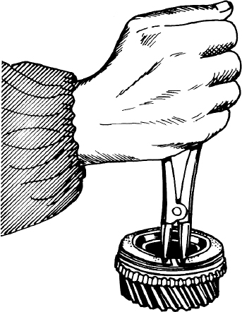
FIG 6:19 Removing the retaining ring from a synchromesh unit
Clamp the layshaft into a vice, using soft vice jaws or suitably padding the layshaft to prevent damage, then remove the nut D. Pull off the roller bearing E and the gear assembly F for fifth and reverse gears. Press off the bearing A.
With the layshaft again held in the vice, remove the nut G and the washer then press off the front bearing H.
Clean all parts with the exception of the clutch release bearing in paraffin and dry them off. The clutch release bearing must not be cleaned with a solvent of any kind as this would destroy the internal lubrication. Wipe the bearing clean with a cloth. Lubricate all the ball and roller bearings after cleaning and turn them between the fingers to check for roughness or side play. If there is any doubt about the condition of a bearing it must be renewed. The clutch release bearing is sealed and lubricated for life and must be renewed if not in good condition.
Clean the inside and outside of the clutch bellhousing, gearbox half casings and the rear cover with paraffin. Remove all traces of old sealing compound from the joint faces, using care to avoid damaging the surfaces. Do not use sharp or pointed tools for cleaning the joint faces as the gearbox case joints fit together without gaskets and oil leakage will result from damaged faces.
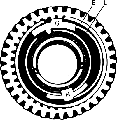
FIG 6:20 First gear synchromesh assembly

FIG 6:21 Second, third, fourth and fifth-speed synchromesh assembly

FIG 6:22 Checking the clearance between the selector fork and the operating sleeve

FIG 6:23 Checking the free movement of the selector shaft interlock pins
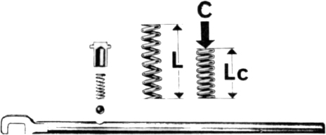
FIG 6:24 Checking the dimensions of the selector lockball springs

FIG 6:25 Renewing the gearbox silentbloc mounting pad with the special tool
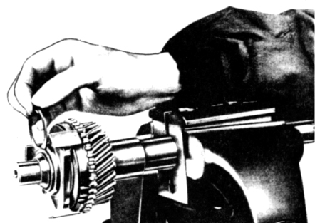
FIG 6:26 Fitting a shim of the correct thickness to take up end play between the retaining ring and the synchronizer hub
Dismantle and inspect the synchromesh units. Refer to FIG 6:19 and remove the retaining ring as shown and check the engaging teeth for signs of wear or seizure. Check that the operating sleeves move freely on the synchromesh hub. Refer to FIGS 6:20 and 6:21 and check for excessive wear on the rings E and that the stop G and segment H show no signs of scoring where they contact strips L. Renew any parts found unserviceable. Reassemble the synchromesh units in the reverse order of dismantling, taking care that the components are installed in the correct original positions (see FIGS 6:20 and 6:21). Check the side clearance between the selector forks and the synchromesh operating sleeves as shown in FIG 6:22. The correct clearance is .006 to .013 inch (.150 to .340 mm), with a wear limit of .033 inch (.850 mm).
Inspect all gearwheels for wear and chipped or damaged teeth. Mount the mainshaft between the centres of a lathe and use a dial gauge to check the runout at the centre of the shaft. Carry out the same operation on the constant pinion shaft. In either case shaft runout should not exceed .002 inch (.05 mm). If runout exceeds this figure a new shaft must be fitted.
Check that the interlock pins arrowed in FIG 6:23 slide freely in their grooves and that the working surfaces of the pins and the selector rods are perfectly smooth. If one of the interlock pins should stick, round off the fillet on the notch in the selector shaft slightly, using a very fine file. Refer to FIG 6:24 and check the locking balls, springs and caps for wear or damage, renewing parts as necessary. Check that the notches in the selector shafts are in good condition. For earlier boxes, the free length of the springs L should be .598 inch (15.2 mm) and the length Lc under a load C of 11 to 12 lb (4.77 to 5.45 kg) should be .394 inch (10 mm). For later boxes, L = 1.41 inch (35.8 mm), C = 17 to 18 lb (7.68 to 8.32 kg) and Lc = .68 inch (17.2 mm).
Remove the old oil seals from the front and rear gearbox covers. Drive in new oil seals, preferably with mandrel A.3.0180, keeping them square. If necessary, renew the Silentbloc mounting pad which supports the gearbox and engine unit. Use tool A.3.0118 for mounting block removal and installation as shown in FIG 6:25. The Silentbloc mounting pad can be renewed without the need for complete gearbox removal but, in this case, it will be necessary to carry out all operations previously detailed for gearbox removal except the removal of the gearbox to engine fixing bolts. The engine and gearbox assembly can then be tilted downwards to gain the necessary access to the mounting pad.
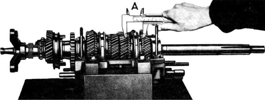
FIG 6:27 Checking for correct shim thickness between the first gear bush and the mainshaft bearing inner race
This is a reversal of the dismantling instructions given earlier. Tighten the layshaft nuts to a torque of 57.8 lb ft.
Press the bearing onto the shaft and refit the shim and retaining ring.
1 Place the mainshaft in tool A.3.0185 and slide on the third-speed gearwheel and the keys. Heat the third-and fourth-speed synchronizer hub to a temperature of 150°C in a hot oil bath or an oven, then fit it to the shaft. Fit the retaining ring and check that there is no end play between the retaining ring and the hub. Any clearance must be taken up by fitting a shim of the correct thickness as shown in FIG 6:26.
2 Turn the mainshaft over and slide the second-speed gearwheel over the shaft with the synchronizing mechanism facing downwards. Heat the first- and second-speed synchronizer hub in the manner previously described then drive it onto the shaft until it abuts against the shaft shoulder. Fit the operating sleeve over the synchronizer hub. Fit the first-speed gearwheel together with the bush and shims. The shims must be of sufficient thickness to ensure that there is no end play when the retaining rings are fitted.
3 Heat the intermediate bearing as previously described and fit it to the shaft, then insert the key. Heat the reverse-speed gearwheel and drive it onto the shaft until it abuts against the face of the bearing. Heat up and fit the fifth-speed synchronizer hub and fit the operating sleeve over the hub. Fit the fifth-speed gearwheel and bush over the shaft. Fit the rear mainshaft bearing, speedometer drive gear and the gearbox drive flange to the shaft, tightening the mainshaft nut to a torque of 56 lb ft. The end clearance of the first-speed gearwheel, which is determined by the first-speed gearwheel bush, should not exceed,0095 inch (.24 mm). The clearance between the second- and third-speed gearwheels, determined by the second-speed gearwheel bush, should not exceed .0083 inch (.21 mm).

FIG 6:28 Measuring the distance between the operating sleeves and the engagement teeth abutment faces

FIG 6:29 Measuring the distance between the fifth-speed operating sleeve and the engagement teeth abutment faces
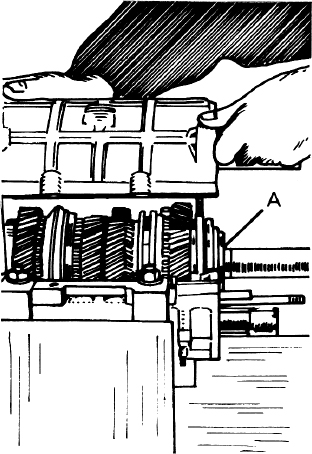
FIG 6:30 Fitting the centralizing ring A to its seat

FIG 6:31 The oil seal protection sleeve in position

FIG 6:32 The components of the floor-mounted gearchange mechanism
Key to Fig 6:32
1 Sleeve
2 Spring
3 Rubber grommet
4 Gearchange lever
5 Bonded rubber block
6 Retaining rod
7 Rubber sleeve
8 Rubber plug
9 Adaptor
11 Washer
12 Retaining pin
13 Clamp
15 Rubber gaiter
16 Retainer
17 Cup washer
18 Nut
19 Sealing washer
20 Dished washer
21 Dished washer
22 Cap
23 Bleeder plug
24 Bearing block
25 Nut
26 Washer
27 Retaining plate
28 Bush
29 Spring
30 Ball
31 Sealing washer
32 Adjusting plate
33 Locking plate
34 Securing screw
35 Selector fork for third and fourth-speed
36 Selector fork for first and second-speed
37 Gearchange lever knob
38 Locknut
39 Spring washer
40 Gearchange lever
41 Nut
42 Washer
43 Securing screw
44 Ball
45 Operating plunger
46 Spring
47 Locking pin
48 Inner selector lever
49 Selector head
50 Bolt
51 Spring
52 Retaining ring
53 Spring seat
54 Stud
55 Bleeder plug
56 Bearing block
57 Nut
58 Washer
59 Stud
60 Selector shaft for first and second-speed
61 Selector shaft for third and fourth speed
62 Selector shaft for fifth and reverse-speed
63 Interlocking plunger
64 Selector fork for fifth and reverse-speed

FIG 6:33 The selector shaft mechanism
Key to Fig 6:33
1 Retaining plate
2 Bush
3 Spring
4 Ball
5 Sealing washers
6 Bush
7 Retaining ring
8 Washer
9 Retaining ring
10 Spring seat
11 Spring
12 Spring collar
13 Spring housing
14 Selector cross-shaft
15 Inner engagement lever
16 Seal ring
17 Seal washer
18 Seal retainer
19 Bush
20 Bracket
21 First and second selector shaft
22 Adjusting plate
23 First and second selector fork
24 Third and fourth selector shaft
25 Interlock plunger
26 Third and fourth selector fork
27 Lockplate
28 Securing screw
29 Fifth and reverse selector fork
30 Fifth and reverse selector shaft
31 Nut
32 Washer
33 Lever securing bolt
34 Washer
35 Nut
36 Gear engagement lever
37 Selector lever
4 Fit the roller bearing into the counterbore in the constant pinion shaft and assemble the mainshaft and constant pinion shaft as shown in FIG 6:16. Fit the layshaft into the gearbox casing half and check that the locking device is positioned correctly. Place the mainshaft and constant pinion shaft assembly into the gearbox casing half and, using an accurate measuring caliper, check that the dimension A in FIG 6:27 is between 1.654 and 1.661 inch (42 and 42.19 mm). If not, the shim thickness between the first-gear bush and the mainshaft bearing inner race must be changed accordingly. Remove the gearbox drive flange and speedometer drive gear from the mainshaft.
5 Place the gearbox in neutral and check that the operating sleeves of third- and fourth-speed and first- and second-speed are equally spaced between the abutment faces of the engaging teeth on the gearwheels as shown in FIG 6:28. Refer to FIG 6:29 and check that the rear edge of the fifth-gear operating sleeve is .394 inch (10 mm) on earlier models or .508 inch (12.9 mm) on 1750 and later models away from the engaging teeth when the gearwheel is in the neutral position. When these checks have been made, correctly adjust the positions of the selector forks on the selector shafts and tighten the selector forks securing screws and tab the lockplates. Engage third gear.
6 Refer to FIG 6:30 and insert the centring ring A in its seat as shown. Fit the reverse idler gear onto the reverse idler shaft. When reassembling the gearbox case the joint faces must be smeared with Permatex No. 3 jointing compound. No gaskets are used. Fit the two gearbox case halves together, then fit the rear cover. When refitting the clutch bellhousing to the gearbox case halves it is recommended that tool A.3.0114 be used to protect the oil seal as shown in FIG 6:31. On cars fitted with floor mounted gear-change, check that the finger of the inner swivel is engaged with the third- and fourth-speed selector shaft. Engage each gear in turn and check that the operation is smooth and light. Refit the selector lever end cover with a new O-ring seal. Fit the speedometer drive gear and the gearbox drive flange and tighten the securing nut to the torque specified in Technical Data and tab the lockplate.

FIG 6:34 Checking and adjusting gear selector control linkage

FIG 6:35 Checking and adjusting gear engaging control linkage
FIG 6:32 shows an exploded view of the floor mounted gearchange mechanism and the selector shaft assemblies. The removal and refitting of the selector shafts and forks is described in Section 6:3. If overhaul of the gearlever mechanism is necessary it should be dismantled into the order shown in FIG 6:32 and faulty components renewed.
FIG 6:33 shows the selector shaft mechanism, the removal and refitting of these components being covered in Section 6:3. After gearbox overhaul or if there has been difficulty in changing gear, the linkage should be checked and, if necessary, adjusted as follows.
Refer to FIG 6:34. Engage first or second gear and check that the gearlever can be moved still further towards the steering wheel as shown in the inset. Engage fifth or reverse gear and check that the gearlever can be moved still further towards the dashboard. The extra travel should be approximately the same in both cases. If there is no travel towards the steering wheel or it is shorter than the travel towards the dashboard, lengthen the pushrod 1 by acting on the adjuster 2. If, alternatively, there is no travel towards the dashboard or it is shorter than the travel towards the steering wheel, shorten the pushrod 1 by acting on the adjuster 2. To adjust the rod, free it from the lever 3 by removing the pivot pin.
Refer to FIG 6:35. Engage first, third or fifth gear and check that the gearlever can be moved still further after engagement. Engage second, fourth or reverse gear and check that the gearlever can be moved still further after engagement. The extra travel should be approximately the same in both cases. If there is no further travel after engaging an odd gear or it is shorter than the travel with an even gear engaged, shorten the pushrod 4 by acting on adjuster 5. If, alternatively, there is no further travel after engaging an even gear or reverse or it is shorter than the travel with an odd gear engaged, lengthen the pushrod 4 by acting on adjuster 5.
If the correct travel adjustments cannot be obtained by the method just described, adjust the lower pushrod 6 by acting on the adjuster 7. To do this, detach the rod 6 from the lever 8 by removing the pivot pin.
(a) Jumping out of gear
1 Broken spring behind selector rod locating ball
2 Excessively worn groove in selector shaft
3 Worn synchromesh units
4 Fork to selector shaft securing screw loose
(b) Noisy transmission
1 Insufficient oil
2 Worn or damaged bearings
3 Worn or damaged gearwheels
(c) Difficulty in engaging gear
1 Incorrect clutch pedal adjustment
2 Worn synchromesh assemblies
3 Worn or loose selector forks
(d) Oil leaks
1 Worn or damaged oil seals
2 Damaged faces on gearbox casing components