11:1 Description
11:2 The battery
11:3 The generator
11:4 The alternator
11:5 The starter
11:6 The control box
11:7 Windscreen wipers
11:8 Headlamps
11:9 Panel and warning lights
11:10 Flasher and traffic hazard warning lights
11:11 Lighting circuits
11:12 Fault diagnosis
All models covered by this manual are equipped with 12-volt electrical systems in which the negative terminal of the battery is earthed. The charging circuit is provided with regulating devices which may be adjusted if necessary, though it must be stressed that accurate meters are required when checking or altering their settings.
There are wiring diagrams in Technical Data at the end of this manual which will enable those with electrical experience to trace and correct faults.
Instructions for servicing the electrical equipment are given in this chapter, but it must be pointed out that it is not sensible to try to repair units which are seriously defective, electrically or mechanically. Such equipment should be replaced by new units which can be obtained on an exchange basis.
To maintain the performance of the battery it is essential to carry out the following operations, particularly in winter when heavy current demands must be met.
Keep the top and surrounding parts of the battery dry and clean as dampness can cause current leakage. Clean off corrosion from the metal parts of the battery mounting with diluted ammonia and paint them with anti-sulphuric paint. Clean the terminal posts and the cable clamps and smear them with petroleum jelly after remaking the connections and tightening the terminal clamps securely. High electrical resistance due to corrosion at the battery terminals can be responsible for a lack of sufficient current to operate the starter motor.
Test the condition of the cells with a hydrometer after topping up the electrolyte level with distilled water to just above the separators. Never add neat acid. If it is necessary to prepare new electrolyte due to loss or spillage, add sulphuric acid to distilled water. It is highly dangerous to add water to acid.
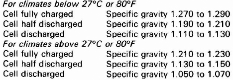
The indications from the readings of the specific gravity are as follows:

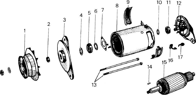
FIG 11:1 The generator components
Key to Fig 11:1
1 Pulley
2 Spacer
3 Drive end bracket
4 Oil deflector
5 Bearing
6 Coverplate
7 Retaining plate
8 Generator housing
9 Coverband
10 Sealing washer
11 Bearing
12 Commutator end bracket
13 Through-bolts
14 Key
15 Armature
16 Brush
17 Brush spring

FIG 11:2 Generator mounting details
These figures assume an electrolyte temperature of 60°F or 16°C. If the temperature of the electrolyte exceeds this, add .002 to the readings for each 5°F or 3°C rise. Subtract .002 for any corresponding drop below 60°F or 16°C.
All of the cells should read approximately the same. If one differs radically from the others it may be due to an internal fault or to spillage or leakage of the electrolyte.
If the battery is in a low state of charge, take the car for a long daylight run or put the battery on a charger at 5 amps with the vent plugs removed until it gasses freely. Do not use a naked light near the battery as the gas is inflammable. If the battery is to stand unused for long periods, give a refreshing charge every month. It will be ruined if it is left uncharged.
The components of the generator are shown in FIG 11:1.
1 Refer to Chapter 4, Section 4:4 and check that a loose drive belt is not the cause of the trouble.
2 Switch off all the lights and accessories. Start the engine and connect an ammeter in series with the battery and control box by disconnecting the red lead from the B + control box terminal, then connecting the ammeter between the terminal and the red wire, Raise the engine speed and check the ammeter reading. The output should be 20 amps minimum at 2500 rev/ min.
3 If the generator is in order, check the continuity of the cables to the control box. If they are in order, remove the ammeter and reconnect the cable, then test the control box as described in Section 11:6.
FIG 11:2 shows the generator and its mounting and adjusting bracket components. Remove the fan belt as described in Chapter 4, Section 4:4 then disconnect the battery. Disconnect the wires from the generator. Remove the adjuster bolt and washers and the two pivot bolts, nuts and washers then lift out the generator.
Refer to FIG 11:1. Remove the brush cover bands 9. Loosen the screw securing the connecting lead to the commutator end bracket and remove the through-bolts and end bracket from the housing. Remove the pulley securing nut and withdraw the pulley from the shaft, using a suitable puller. Remove the key 14 from the shaft and pull off the drive end bracket. Remove the bearing retainer plate and press the bearing from the drive end bracket.
Lift the brushes up in their holders and secure them by positioning each spring at the side of its brush. Fit the commutator end bracket over the commutator and release the brushes. Hold back each spring in turn and move the brushes by pulling gently on their flexible connectors. If a brush moves sluggishly or sticks in its holder, remove it and ease the sides against a smooth file. Refit in its original position. Renew and bed to the commutator any brush which is less than the permissible minimum of .47 inch in length. Renew any brush spring which gives a spring balance reading of less than 16 oz.
A commutator in good condition will be smooth and free from pitting and burned segments. Clean with a cloth and petrol and, if necessary, polish with fine glasspaper. Do not use emerycloth. Skim a badly worn commutator in a lathe, using a high speed and taking a light cut with a sharp tool. Remove the minimum amount necessary to clean up, then polish with fine glasspaper. Undercut the insulation between the segments to a depth of .002 inch using a special saw or a hacksaw blade ground to the thickness of the insulation.
In the absence of armature testing facilities, the only check for faults which an owner can make is to substitute one which is known to be serviceable. Alternatively, have the armature tested for open circuits or internal earthing at a service station, fitting a new component if faults are indicated.
When testing with an ohmmeter, the reading should be between 3.5 and 3.85 ohms. If the reading is less than 3.5 ohms the field coils must be renewed by a service station.
It is most unlikely that noticeable bearing wear will occur during the life of the generator. However, if bearing wear is encountered, the bearings in the commutator end bracket and drive end bracket should be renewed.
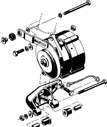
FIG 11:3 Alternator mounting details
This is the reverse of the dismantling procedure. If new brushes have been fitted, place a strip of fine glasspaper round the commutator and grind them in until they make good contact on their bearing faces. Reconnect the lead to the commutator end bracket and refit the brush cover bands. Adjust the fan belt tension as described in Chapter 4, Section 4:4.
FIG 11:3 shows the mounting and adjustment bracket components of a typical Bosch alternator installation.

FIG 11:4 The alternator components
Key to Fig 11:4
1 Pulley
2 Cooling fan
3 Spacer
4 Drive end bracket
5 Bearing
6 Retaining plate
7 Spacer
8 Securing ring
9 Rotor
10 Slip rings
11 Stator
12 Brush holder
13 Bearing
14 Shim
15 Negative diodes
16 Rear end bracket
17 Field diodes
18 Positive diodes
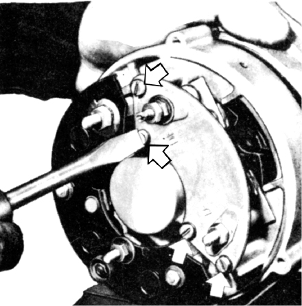
FIG 11:5 Removing the diode cover and brush holder

FIG 11:6 Removing the drive end bracket
Refer to the previous section for testing a generator and carry out instructions 1, 2 and 3. The ammeter reading when testing an alternator should be 30 amps minimum at 2500 rev/min.
Remove the fan belt as described in Chapter 4, Section 4:4 then disconnect the battery. Disconnect the wires from the alternator. Remove the securing bolts and lift out the alternator.
Refer to FIG 11:4. Unscrew the retaining nut and remove the pulley and fan from the rotor shaft. Remove the diode cover and brush holder as shown in FIG 11:5. Mark the drive end bracket, stator and rear end bracket to ensure correct reassembly, then remove the drive end bracket as shown in FIG 11:6 together with the rotor assembly. Use a puller to remove the drive end bracket from the rotor shaft as shown in FIG 11:7.
From the rear of the alternator dismantle the diode holders into the order shown in FIG 11:8. Unscrew the bearing retainer from the drive end bracket as shown in FIG 11:9 and remove the ballbearing from the bracket. Use a suitable puller to remove the rear bearing from the rotor shaft.
Check the brushes and renew them if they are worn to a length of  inch or less. Unsolder the connecting wire and remove the old brush. When soldering the connecting wire to attach a new brush, hold the wire to the work with a pair of flat-nosed pliers to prevent the solder from flowing down the wire strands, otherwise the wire will become rigid and the brush unserviceable. Check that the brushes move freely in their holders. If a brush binds or sticks, remove it and ease the sides against a smooth file.
The faces of the slip rings must be in a clean and polished condition. Clean them with fine sandpaper and polish them. To avoid causing flat surfaces on the slip rings this operation is best carried out while spinning the rotor assembly in a lathe.
Test the rotor windings and slip rings electrically, using a test lamp or ohmmeter as shown in FIG 11:10. A test lamp should not light up; an ohmmeter should indicate near infinite resistance. Test the rotor windings for short-circuits by connecting the ohmmeter between the two slip rings as shown in FIG 11:11. The reading obtained should be between 4.0 and 4.4 ohms. If any test is failed, the rotor and slip rings assembly is faulty and must be renewed.

FIG 11:7 Removing the drive end bracket from the rotor shaft
Test the stator windings for earthing by connecting a test lamp or an ohmmeter in the manner shown in FIG 11:12. A test lamp should not light up; an ohmmeter should indicate near infinite resistance. Check the stator windings for shortcircuits, using a low-reading ohmmeter as shown in FIG 11:13. Check two phases at a time, connecting the ohmmeter between the wire ends alternately. The readings should be between .26 and .29 ohms. If any test is failed, the stator assembly is faulty and must be renewed.
If the alternator current output is low, one or more of the diodes may be defective. FIG 11:14 shows the diode configuration in the alternator charging circuit, while FIG 11:15 shows the current flow through diodes of both positive and negative types. Carefully disconnect each diode before testing it, otherwise it will not be possible to determine which diode, if any, is at fault. Use a 12-volt test lamp and current supply. Connect the test lamp between the diode connection and housing, then reverse the connections. The test lamp should light brightly in one direction, but should not light at all in the other direction. Diodes in each set of three should pass and block current in the same direction as others in the set. Any diode that fails the tests should be renewed by a service station, using special press equipment.
This is a reversal of the removal procedure, noting the following points. Reconnect any diodes that were disconnected during servicing, using a very hot soldering iron and working quickly to avoid damaging the diodes, which are very sensitive to heat. Lubricate both alternator bearings with high melting point grease. On completion, adjust the fan belt tension as described in Chapter 4, Section 4:4.
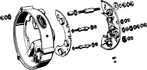
FIG 11:8 The diode support assemblies

FIG 11:9 Removing the bearing retainer from the drive end bracket
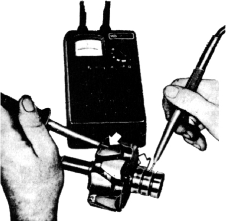
FIG 11:10 Testing the rotor windings and slip rings
The Bosch starter is a brush type series wound motor equipped with an overrunning clutch and operated by a solenoid. The armature shaft is supported in sintered bronze bushes which are factory packed with lubricant and require no servicing between overhauls. FIG 11:16 shows the starter components. When the starter is operated from the switch, the engagement lever moves the pinion into mesh with the flywheel ring gear. When the pinion meshes with the ring gear teeth, the solenoid contact disc closes the circuit and the starter motor operates to turn the engine over. When the engine starts, the speed of the flywheel causes the pinion to overrun the starter clutch and armature. The pinion continues to be engaged in the ring gear teeth until the engagement lever is released, when it returns under spring action.

FIG 11:11 Testing the rotor for shortcircuits
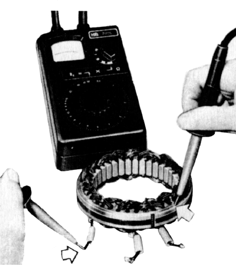
FIG 11:12 Testing the stator windings for earthing
Check that the battery is in good condition and fully charged and that its connections are clean and tight. Switch on the headlights and operate the starter switch. Current is reaching the starter if the lights go dim, in which case it will be necessary to remove the starter for servicing. If the lights do not go dim, check the switch and the starter cables. Check the brushes by the method described later, it not being necessary to remove the starter to do this. If the switch, cables and brushes are in order, the starter must be removed and serviced.
Disconnect the battery, the main starter lead and the control wire. Remove the starter mounting bolts and lift out the starter.
Remove the brush cover from the starter and detach the brushgear, marking the position of the brushes for correct reassembly. Renew any brush which is worn to less than  inch in length. If a brush binds or sticks in its holder, remove it and ease the sides against a smooth file. When fitting new brushes, hold the connecting wire close to the work with a pair of flat-nosed pliers to prevent solder from flowing down the wire strands, otherwise the wire will become rigid and the brush unserviceable.
Remove the brushgear as previously described. Remove the screws attaching the small cover at the end of the shaft and detach the cover. Remove the lockwasher and shim from the shaft and remove the two through-bolts. Detach the commutator end bracket then remove the brush holder plate, collecting the shims between the plate and the commutator.
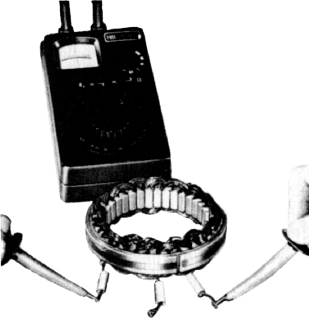
FIG 11:13 Testing the stator windings for shortcircuits
Detach the starter solenoid by removing the two screws shown in FIG 11:17. Remove the rubber and metal plate from the drive end bracket as shown in FIG 11:18. Remove the engagement lever pivot pin, engagement lever and the armature from the drive end bracket. Drive back the retaining ring on the armature shaft and remove the circlip, then pull off the retaining ring, overrunning clutch and pinion assembly.
Clean the commutator with a cloth and petrol and, if necessary, polish with fine glasspaper. Do not use emerycloth. Skim a badly worn commutator in a lathe, using a high speed and taking a light cut with a sharp tool, noting that the minimum diameter for starter motor commutators is 1.25 inches. If cleaning up would remove enough metal to reduce the diameter below this figure the armature must be renewed. Undercut the insulation between the segments to a depth of .002 inch using a special saw or a hacksaw blade ground to the thickness of the insulation.
A damaged armature should always be renewed. No attempt should be made to straighten a bent shaft or to machine the core.
Test the continuity with a 12-volt test lamp and current supply between the terminal post and each field brush in turn. Test for breakdown of the insulation by connecting a test lamp between the terminal post and the starter body. If the lamp lights, defective insulation is indicated. The renewal of field coils should be entrusted to a service station.
Press out the old bearing bushes if they are worn and renew them as follows. Allow the new bushes to stand fully immersed in engine oil for at least 30 minutes before pressing them into the starter brackets. Press them into position with a shouldered mandrel having a polished pilot of the same diameter as the armature shaft and slightly longer than the bushes.
Do not clean the overrunning clutch with solvents as this would wash the grease from inside the clutch. Check the components for wear or damage and renew any found unserviceable. Coat the armature shaft splines and the contact areas for the engagement lever with high melting point grease.
These operations are the reverse of the dismantling and removal instructions.
The control box on cars equipped with alternators contains only a voltage regulator, the use of diodes in the alternator making a cut-out relay unnecessary. The alternator charging circuit is shown in FIG 11:14.
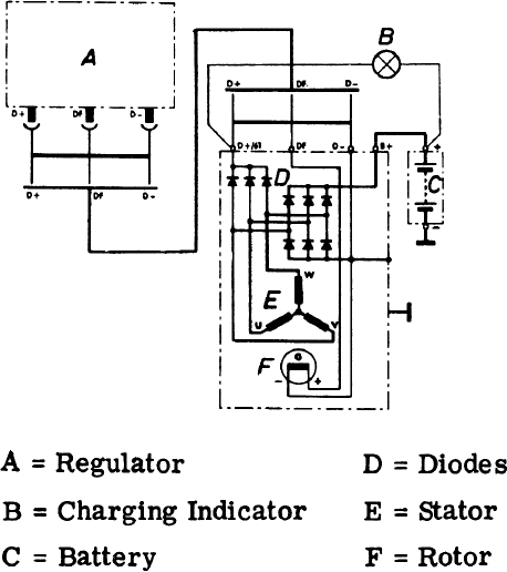
FIG 11:14 The alternator charging circuit
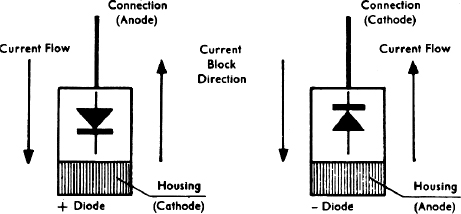
FIG 11:15 Current flow through positive and negative diodes
On cars equipped with generators the control box contains a voltage regulator and a cut-out relay, this type of circuit being shown in FIG 11:19.
Do not disturb the control box settings until the generator or alternator has been checked as described in Section 11:3 or 11:4.
It must be stressed that the use of first grade electrical meters is essential to check and make any necessary adjustments to the control box. All checks and adjustments must be made as quickly as possible to avoid errors due to heating up of the control box operating coils. If the control box fails to respond correctly to any adjustment it should be examined at a service station.
1 Remove the red battery lead from the control box B + terminal. Connect the voltmeter positive lead to the B + terminal and the negative lead to earth on the base of the control box.

FIG 11:16 The starter components
Key to Fig 11:16
1 Through-bolts
2 Solenoid
3 Drive end bracket
4 Bush
5 End cap
6 Retainer
7 Shims
8 Rubber seal
9 Bush
10 Commutator end bracket
11 Negative brush plate
12 Fibre washer
13 Washer
14 Positive brushes on field coils
15 Starter motor housing
16 Armature
17 Rubber washer
18 Washer
19 Engagement lever
20 Pinion and clutch
21 Bush
22 Thrust washer
23 Retainer
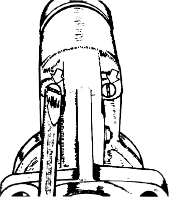
FIG 11:17 Removing the starter solenoid
2 Start the engine and slowly increase its speed while observing the voltmeter. The reading should be between 13.5 and 14.5 volts. If the reading is not within the specified range, remove the control box cover and adjust the voltage regulator armature spring to obtain a reading between the figures quoted. If the reading fluctuates, the contacts are dirty and must be cleaned as described later.
3 Replace the control box cover and recheck the setting.
1 Connect the voltmeter positive lead to the control box terminal 61 and the negative lead to earth. Connect an ammeter in series with the B + terminal and disconnect the red wire.
2 Start the engine and increase the speed while observing the voltmeter. The voltage will increase until the cut-out relay points close, then drop slightly as the circuit is completed to the battery. The highest voltage reading just before it drops off is the closing voltage. This voltage should be between 12.3 and 13.4 volts. If the voltage as tested is not between these limits, remove the control box cover and adjust the closing voltage by bending the cut-out relay spring support. Increase the tension on the spring to increase the closing voltage, decrease tension to decrease the voltage.
3 Replace the control box cover and recheck the setting.
Clean the contact points in the voltage regulator and cut-out relay with fine glasspaper. Clean off all dust with methylated spirits.
The wiper assembly consists of a permanent magnet type motor with a reduction gearbox driving the wiper arms through a connecting linkage. Apart from renewal of worn wiperblades the wiper assembly needs no routine maintenance.
If the motor is completely inoperative, check the fuse and the connections at the fuse block and wiper switch. Disconnect the positive lead from the wiper motor terminal, turn on the ignition and wiper switches and use a voltmeter to check the voltage available to the motor, which should be 12-volts if the battery is fully charged. A further check can be made by connecting a temporary lead between the battery and the positive terminal of the wiper motor. If the motor then runs the fault is in the wiring circuit or switch. If not, the motor must be removed for service.

FIG 11:18 Removing the rubber and metal plate from the drive end bracket

FIG 11:19 The generator charging circuit
Key to Fig 11:19
1 Voltage regulator spring
2 Cut-out relay points
3 Cut-out relay spring
4 Cut-out relay current coil
5 Iron core of cut-out relay
6 Cut-out relay voltage coil
7 Cut-out relay armature support
8 Variode
9 Ignition switch
10 Charging indicator lamp
11 Battery
12 Field coils
13 Generator armature
14 Resistor
15 Iron core of regulator
16 Regulator voltage coil
17 Regulator lower points
18 Regulator armature support
19 Regulator upper points
20 Regulator control coil

FIG 11:20 Components of a Bosch wiper motor
Key to Fig 11:20
1 Attaching screws
2 Transmission cover
3 Nut
4 Play pin (threaded end)
5 Gasket
6 Ball
7 Driven gear
8 Washer
9 Play pin (threaded end)
10 Sleeve
11 Mounting plate
12 Gasket
13 Toothed washers
14 Attaching screws
15 Transmission housing
16 Negative brush
17 Attaching screw
18 Retaining plate
19 Positive brush
20 Wire
21 Thrust spring
22 Rubber mounts
23 Armature
24 Attaching screws
25 Lockwasher
26 Angle brackets
27 Motor housing
28 Magnet ring
29 Magnet threaded pin locators
30 North pole paint marking on this side
If the wiper operation is sluggish, detach the linkage crank arm from the motor and operate the wipers by hand to check for binds in the linkage.
Detach the crank arm from the motor drive shaft, then disconnect the electrical connections and the wiper motor attaching nuts. Refit in the reverse order, making sure that the wiring is reconnected correctly.
FIG 11:20 shows the components of the Bosch wiper motor, FIG 11:21 the components of the Marelli wiper motor. Remove the transmission housing together with the armature from the motor housing and check that the brushes are free and that the brush springs function adequately. Renew the brushes if they are less than .24 inch in length. To remove a negative brush, remove the retaining screw from the commutator end frame. To remove a positive brush, the lead must be cut off at the brush holder. New positive brushes must be soldered into position, making sure that the solder does not run down the flexible lead as this would stiffen the lead and make the brush unserviceable. Clean the commutator with a cloth and petrol and polish with fine glasspaper. Lightly oil the armature shaft and lubricate the transmission with the correct grade of grease.

FIG 11:21 Components of a Marelli wiper motor
Key to Fig 11:21
1 Lockwasher
2 Limit stop control plate
3 Grommet
4 Screw
5 Field coil shoe
6 Field coil
7 Brush spring
8 Brush
9 Seal ring
10 Lockwasher
11 Brush holder
12 Through-bolt
13 Armature
14 Field coil
15 Housing
16 Wiring assembly
17 Seal ring
18 Screw
19 Protection cover
20 Screw
21 Lockwasher
22 Connection fastener
23 Cover
24 Gasket
25 Nut
26 Lockwasher
27 Gear
28 Shim
29 Thrust bearing
30 Adjusting screw
31 Drive end cover
32 O-ring seal
33 Plastic washer
34 Spring washer
35 Protection cover
36 Crank arm

FIG 11:22 The headlamp beam setting screws
Headlamps, of which there may be two or four according to model, should be set so that, when the car is in an unloaded condition, the main beams are parallel to each other and to the road. FIG 11:22 shows the headlamp adjustment screws which are accessible when the headlamp rim has been removed. Screw V is used to adjust the vertical alignment, screw O to adjust the horizontal alignment. Accurate beam setting is best carried out by a service station having special beam setting equipment.
The removal of the instrument panel will give access for the replacement of instrument and warning lights. When working on electrical units in this manner, the battery should be disconnected to avoid the occurence of accidental shortcircuits.
The flasher unit, in which a switch is operated by alternate heating and cooling of an actuating wire, is housed in a small cylindrical container behind the dashboard. A small relay to flash the pilot light is incorporated.
In case of trouble check the bulbs and main fuses. If one bulb is defective, the other bulb and the pilot light will flash at twice the normal speed, which will indicate this fault. If the flasher unit is defective it must be renewed. Mark the connections before removing the old unit to ensure that the new unit is correctly wired.
This system, when fitted, operates in conjunction with flashing direction indicator lights. When the hazard warning light switch on the instrument panel is turned on, all four flasher lights operate simultaneously through the flasher unit. The system will operate with the ignition switched off so that, if necessary, the car can be locked up and the lights left flashing in the event of a breakdown. As the system is meant as a warning to other traffic of a stationary vehicle, the hazard warning should not be switched on when the car is moving.
Refer to Section 11:2 and check the condition of the battery. Recharge if necessary. Check the setting of the headlights as described in Section 11:8 and renew any bulbs that have darkened with age.
Refer to Section 11:6 and check the control box settings.
Refer to Section 11:2 and check the battery as it is not capable of supplying current for any length of time.
Check the condition of the battery and its connections. Make sure they are tight and renew any faulty cables.
(a) Battery discharged
1 Terminal connections loose or dirty
2 Shorts in lighting circuit
3 Generator or alternator not charging
4 Control box faulty
5 Battery internally defective
(b) Insufficient charging rate
1 Check 1 and 4 in (a)
2 Drive belt slipping
(c) Battery will not hold charge
1 Low electrolyte level
2 Battery plates sulphated
3 Electrolyte leakage from cracked case
4 Battery plate separators defective
(d) Battery overcharged
1 Control box needs adjusting
(e) Generator or alternator output low or nil
1 Belt broken or slipping
2 Control box out of adjustment
3 Worn bearings, loose polepieces
4 Commutator worn, burned or shorted
5 Armature shaft worn or bent
6 Insulation proud between segments
7 Brushes sticking, springs weak or broken
8 Field coil windings broken, shorted or burned
9 Alternator diode(s) defective
(f) Starter motor lacks power or will not turn
1 Battery discharged
2 Starter pinion jammed in flywheel ring gear
3 Starter switch or solenoid faulty
4 Brushes worn or sticking, leads detached or shorting
5 Commutator dirty or worn
6 Starter shaft bent
7 Engine abnormally stiff, perhaps due to rebore
(g) Starter runs but does not turn engine
1 Pinion engagement mechanism faulty
2 Broken teeth on pinion or flywheel gears
(h) Noisy starter pinion when engine is running
1 Pinion return mechanism faulty
(j) Starter motor inoperative
1 Check 1 and 4 in (f)
2 Armature or field coils faulty
(k) Starter motor rough or noisy
1 Mounting bolts loose
2 Damaged pinion or flywheel teeth
3 Pinion engagement mechanism faulty
(l) Lamps inoperative or erratic
1 Battery low, bulbs burned out
2 Faulty earthing or lamps or battery
3 Lighting switch faulty, loose or broken connections
(m) Wiper motor sluggish, taking high current
1 Faulty armature
2 Commutator dirty or shorting
3 Brushes worn or sticking, springs weak or broken
4 Lack of lubrication
5 Linkage worn or binding
6 Wiper motor fixing bolts loose
7 Motor transmission binding, no armature shaft end float
(n) Wiper motor runs but does not drive arms
1 Wiper linkage faulty
2 Transmission components worn
(o) Fuel, temperature or pressure gauges do not work
1 Check wiring for continuity
2 Check instruments and transmitters for continuity