Chapter 17
Using Assembly Tools
SolidWorks assemblies enable you to take advantage of several tools in addition to the standard and best known functionality. The tools covered in this chapter are general tools that have wide application throughout assembly topics.
Placing Parts without Mates
Assembly mates are great tools, but they aren't the only tools for placing parts in an assembly. Sometimes, you might need to place parts without applying a mate, such as when you are setting up an animation and the mate would prevent the animation from working correctly. You might also want to place a part and allow motion of the part it is placed relative to while making sure the part itself remains stationary.
In a perfect world, assembly mates are well controlled and easy to understand. But in reality, sometimes things happen that you cannot explain. If you build an assembly without mates (with the parts simply positioned in space using any technique that works), the parts are guaranteed not to move unless you accidentally move one.
On the other hand, if your design changes and you want a set of parts to move together, they will not. You have to change their positions by whatever means you used to get them to their current positions.
As a final touch for an assembly of parts that have nothing holding them in place, you might consider fixing the parts in place. Using the Fix and Float commands with parts is easy, and knowing that parts will not move brings peace of mind.
There is also a Locked mate, which creates a relationship between selected parts, but allows those parts to move relative to other parts.
Using the Move Component Options
 The Move Component tool has several options for locating parts without using mates. These options are shown in Figure 17.1.
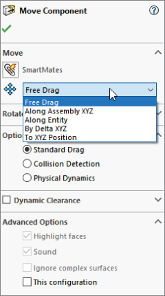
FIGURE 17.1 Selecting a positioning option with Move Component
This section describes how to use the Free Drag, Along Assembly XYZ, and Along Entity methods with the Move Component command, but these methods are also available in the Rotate section of the Move Component PropertyManager interface.
Both Move and Rotate enable you to select Standard Drag, Collision Detection, or Physical Dynamics under the Options section. Collision Detection and Physical Dynamics are described in a later section of this chapter. The methods described in this section for moving components assume the use of the Standard Drag option.
USING FREE DRAG
The Free Drag option of Move Component enables you to simply move the part around the screen by dragging with the cursor. This is the same as the default function of the cursor when in an assembly. Click a part and drag. The part follows any existing mates and moves the part in 3D space. For a part that is completely unconstrained, it moves in a plane parallel to the screen. If you are viewing the assembly such that the screen isn't parallel to any standard plane, the part you are moving may be moving in and out of the assembly or in some other unexpected manner. If you have some mates applied to the part, it is less likely to do something odd. You might consider using the Four View option to move parts using this method.
Free Drag is not a great method to precisely position parts, but it is okay if you are just trying to position something visually as a prop for a rendering.
MOVING ALONG ASSEMBLY XYZ
When you drag a part in an assembly with the Along Assembly XYZ option enabled, the part can move only along the X-axis, the Y-axis, or the Z-axis at one time. It can't move at an angle. To use this option properly, you should use an orthogonal view so it's easier for you to get the part going in the correct direction and easier to see which direction it's heading. Again, using the Four View display option would also be helpful.
If you want to change directions, you must stop dragging and then restart the drag, getting the initial direction of the drag in the direction you want to move the part.
MOVING ALONG ENTITY
The Along Entity option for Move Component is similar to the Along Assembly XYZ option except that you select a custom direction and the part can move only back and forth along that direction. The custom direction must be either linear or planar, and it can be an edge, axis, face, plane, sketch line, and so forth.
MOVING BY DELTA XYZ
The By Delta XYZ method is the first that offers direct numerical input for moving parts. Delta means change, so the numbers you enter change the position of the part along the specified axis. Figure 17.2 shows the PropertyManager interface for this part-moving option.
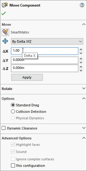
FIGURE 17.2 Using the By Delta XYZ option to move parts
Because this is the first move option that uses an Apply button, shown in Figure 17.2, you can move a selection of parts multiple times just by entering a number in one of the boxes and clicking Apply multiple times. Each time you click Apply, it moves by the amounts listed in the three boxes ∆X, ∆Y, or ∆Z. Remember that you can create selection sets—which can include parts and subassemlbies—to save in the FeatureManager, which include parts in an assembly.
This does not work the same way as the Modify dialog box for dimensions, where if you change the number and click the check mark, the dimension changes from, say, 3 inches to 5 inches. If you have 3 in the ∆X box, and click Apply, it moves 3 inches. If you then change ∆X to 5 and click Apply again, it moves 5 inches for a total of 8 inches. If the second time you used –5 instead of 5, the total movement would be 2 inches in the opposite direction from the original 3 inches.
Also notice that the interface does not have a selection box to tell it which parts you want to move. To select a part to move, you can select a face from the graphics window, or select a part or subassembly in the FeatureManager. Clicking Apply moves all the parts selected.
You can even change selections while the command is active. So you can move one selection of parts and then move a different selection.
USING TO XYZ POSITION
Using the To XYZ Position option is also different from the By Delta XYZ option. You may find that this option has a few quirks. First, it is intended to move the selected point of the selected part to the XYZ location you keyed into the X, Y, and Z boxes.
Again, this PropertyManager does not have a selection box to list parts to move or points to move to the specified XYZ location. That makes this interface a little more limited than some of the other options.
If you do not select a point, SolidWorks assumes you want to move the origin of the part. If you have multiple parts selected, it assumes you want to move the center of gravity (CG) of the combined parts.
If, in a previous move, you did have a point selected on an instance of the part and you then moved a different instance, SolidWorks assumes you wanted to position the same point on the second instance of the part.
The rules for which point gets positioned are not spelled out and are too difficult to follow. If I were to use this option, I would position only origins or points, and if I were to change between origins and points, I would cancel the command and restart it.
You can select multiple parts by selecting them from the assembly FeatureManager; however, it does not appear to allow you to select points to position anymore.
If you select a point on a part and then want to change to a different point on the same part, you can't do that. You have to first select a point on another part, and then select a different point on the original part.
In general, this option appears to be underdeveloped. This means that it may not have all the flexibility you are looking for, or it might appear to have quirks if you don't follow the perfect workflow process every time.
USING MOVE WITH TRIAD
The Move With Triad tool is different from the Move/Copy Bodies feature. Move/Copy Bodies is found in the part environment and is intended to help move individual solid and surface bodies by using a Triad with arrows, wings, and rings, shown in Figure 17.3. Another difference between Move/Copy Bodies and Move With Triad is that Move/Copy Bodies creates a feature in the tree, but Move Component does not.
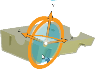
FIGURE 17.3 The Triad for Move Bodies works the same as it does for Move With Triad.
Move With Triad, unlike Move Component, is available only from the RMB menu on parts and subassemblies in the graphics window and the FeatureManager. On some menus (such as RMB in the FeatureManager, but not RMB in a graphics window), you will have to expand the menu if you are using truncated menus.
Move With Triad enables you to move components by dragging along the orange axes, on the wings (transparent planes), or around the rings of a Triad symbol in the display. To select which entity is being used to move or rotate the part, move the cursor around the Triad, and various elements will turn blue. You can reposition the Triad itself (to rotate around a different center) by dragging and dropping the white ball at the origin of the Triad.
Using the For Positioning Only Option
The Mate PropertyManager has an option called Use For Positioning Only, which is shown in Figure 17.4.
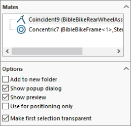
FIGURE 17.4 Using the Use For Positioning Only option
This option has been in the software for a long time, but it may not be taught in the standard SolidWorks reseller class or demonstrated in most tutorials on the market. This option essentially allows you to go through the motions of creating a mate; however, when you are finished, the part you are positioning will be in place, but it will have no mate.
The result is similar to using any of the tools described in the preceding section of this chapter, but you don't have to calculate a position or movement amount; the new position is driven by geometry on another part.
The people I have talked to who use this option tend to use it for visualization—to help see the part in position before they commit to a method of attaching it. Usually, people who use the positioning-only option wind up mating the part completely later, but they may consider multiple mate strategies that achieve the desired goal more efficiently or cleanly.
Why would you want to go through all the work of creating a mate and then not have a mate to show for it? Possibly to avoid deleting it later or to avoid conflicts that it might cause later. For example, when trying to define the initial position between a chain link and a sprocket, you want the link to be concentric to the sprocket tooth gap, but a concentric mate would block the movement of the chain when you are using a Rack and Pinion mate. If you use a concentric mate for positioning and then add a rack and pinion, everything is peachy. If you are working in reverse, the part you are placing without the mate should be the fixed part, so you place it, fix it, and mate other parts to it. Sometimes with animations, you want parts placed correctly without a mate to interfere with the animated motion of the part.
So why wouldn't you create the mate and then just suppress it? Configurations can be complicated enough without adding a configuration just to remove a mate. One case in which the position-only option might be used is with packaging design. You could place the packaging around the product without mates so you can use in-context techniques without ill effects later.
Building Parts in Place
Building parts in place, like the method shown in Chapter 16, “Working with Assembly Sketches and Layouts,” is a relatively easy way to place parts without mating them. This technique might be called top-down, or in-context, and is dealt with in other chapters of this book. I mention it here to introduce the method while pointing to other chapters for the details.
Using Proximity Tools
SolidWorks has several tools that are meant to detect proximity between parts in an assembly:
- Interference Detection
- Clearance Verification
- Collision Detection
- Physical Dynamics
- Sensors
Using Interference Detection
 Interference Detection is available through the menus at Tools ➢ Evaluate ➢ Interference Detection. You can also find it in the Evaluate tab of the CommandManager. It is a stand-alone tool that finds existing interferences in an assembly. The PropertyManager for Interference Detection is shown in Figure 17.5, after detecting interferences in an assembly.
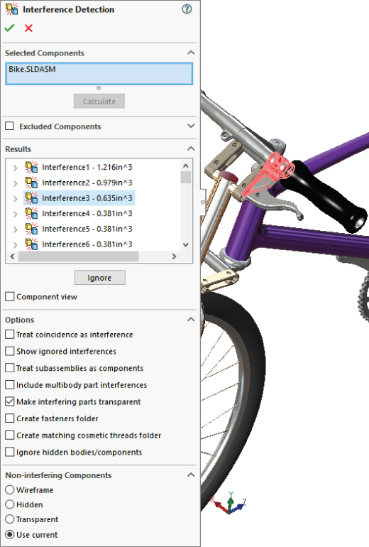
FIGURE 17.5 Finding interferences in an assembly
You can use two different types of selections for Interference Detection. The first type is to simply select the top-level assembly from the assembly FeatureManager. This checks all the parts in the assembly for interference. The second method is to select individual components (parts or subassemblies) from the assembly FeatureManager. In either case, click the Calculate button when you are finished with the selection and ready to see the interferences.
DISPLAYING THE RESULTS
The default result display (shown in Figure 17.6) shows each interference with the pair of interfering components underneath the interference. Interferences are listed with the size (volume) of the interferences.
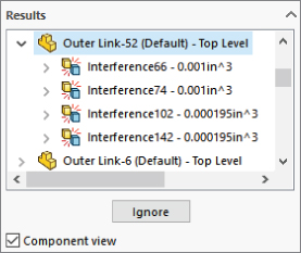
FIGURE 17.6 Displaying interference results with the Component View option
Remember that you cannot judge the size of a number just by looking at the left-most digit. The numbers are listed in scientific notation, so 1.05e-005in^3 means 1.05 × 10^–5 cubic inches (read that as 1.05 times 10 to the negative 5 power), or 0.0000105 cubic inches. Interferences are not listed in any order, but can be sorted by size.
As you click each interference, the interfering volume highlights in red in the graphics window. You can also right-click an interference and select Zoom To Selection if the interference is very small.
IGNORING INTERFERENCES
You can ignore an interference by right-clicking the interference in the Results panel and selecting Ignore from the menu or by clicking the Ignore button in the Results panel. You can also ignore interferences Smaller Than. After an interference is ignored, it is simply removed from the list. You can Shift+select or Ctrl+select to ignore multiple interferences at once. A counter immediately under the Results list keeps track of how many ignored interferences there are. After an interference is ignored, you can get it back into the Results panel by enabling the Show Ignored Interferences option in the Options panel. Ignored interferences are displayed as grayed out. After the grayed-out interferences are shown, you can select them in the list and use the Un-ignore button or select them from the RMB menu.
USING COMPONENT VIEW
The Component View option at the bottom of the Results panel toggles from the default display, where components are listed under each interference, to the component view in which all components are listed. The interference volumes are listed under the component, and under the interference is listed the other interfering part, as shown in Figure 17.6.
SELECTING OPTIONS
The Options panel is shown in Figure 17.5. Most of the options are self-explanatory. There are, however, a couple of items to note: You cannot do body interference checks in multibody parts, but you can include multibodies in the assembly interference detection.
In addition, when the Make Interfering Parts Transparent option is used with the display option in the Non-interfering Components panel, the entire assembly is shown as transparent except the interfering volume, which is displayed opaque. The Make Interfering Parts Transparent option is turned on by default, and the noninterfering-components default option is Use Current.
DISPLAY OPTIONS FOR NONINTERFERING COMPONENTS
The final panel of the Interference Detection PropertyManager controls the display of noninterfering components. You have the option of making them wireframe, hidden, or transparent, or you can leave the display properties alone. I personally prefer the Hidden option because it offers the most contrast with the interfering parts to make the interferences stand out.
You can also eliminate fasteners and cosmetic threads that can create false or unwanted interferences. Note that the software does not give the option to distinguish between screw heads and threads. Interferences from threads may not be significant, while head interferences are.
Using Clearance Verification
 Clearance Verification enables you to check that clearances between parts in an assembly or model faces are at least a certain amount. The tool lists any clearances that are less than the clearance you specify, which means it identifies interferences as well as clearances. This is for clearances between static parts, not between moving parts. For clearances between moving parts, use the Dynamic Clearance option in the Move Component PropertyManager described later in this chapter.
You can find the Clearance Verification tool in the menus at Tools ➢ Clearance Verification or on the Evaluate tab of the CommandManager. The Clearance Verification PropertyManager is shown in Figure 17.7.

FIGURE 17.7 Using the Clearance Verification PropertyManager
The secret to using Clearance Verification is to understand what it measures. Clearance Verification is concerned only with clearances less than the distance you specify. This means that parts that touch or interfere are listed as “Clearances” in the Results box.
If you want to find the minimum clearance between two parts in an assembly, this tool can do that, but you must enter a value in the Minimum Acceptable Clearance box that is larger than the clearance you are looking for. A value of zero will return all interferences. If you are looking for the minimum clearance between two parts, you may get a more intuitive result using the Dynamic Clearance options, which are part of the Move Component tool.
The Clearance Verification PropertyManager shown in Figure 17.7 is in many ways similar or identical to the Interference Detection PropertyManager (refer to Figure 17.5). The results can be fairly similar as well.
Using Dynamic Clearance
The Dynamic Clearance options are part of the Move Component tool. Move Component is on the Assembly toolbar. Dynamic Clearance has a panel of its own in the middle of the Move Component PropertyManager.
To use Dynamic Clearance, activate the selection box shown in Figure 17.8 and pick two parts that can move relative to one another. In this case, I'm using the fork assembly from the Bike model in the download files, selecting the fork and the stem.
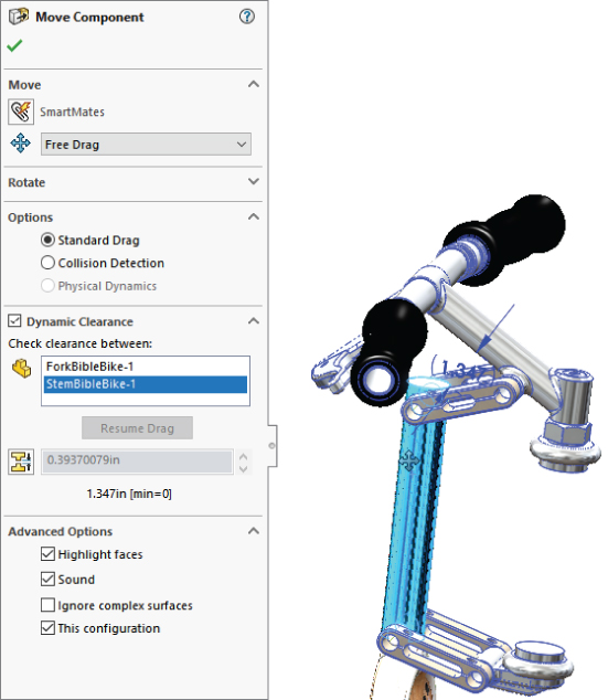
FIGURE 17.8 Using the Dynamic Clearance options in Move Component
The Dynamic Clearance panel has an icon that looks exactly like the Clearance Verification icon, described earlier in this chapter. Clicking the icon enables you to enter a Clearance value. This Clearance value is the minimum clearance that the tool allows when you move the parts around. If the clearance reaches that value, the motion will stop.
Notice the dimension in parentheses (1.347) in Figure 17.8. This is the minimum clearance between the stem and the fork, and it changes dynamically as you move one of the parts. If you specify a minimum clearance value, SolidWorks stops the motion of the part you are dragging when the clearance between the parts reaches that number.
Using Collision Detection
Collision Detection is another tool available in the Move Component PropertyManager, and it can be used at the same time as Dynamic Clearance. You turn on Collision Detection in the Options panel of the Move Component PropertyManager. When you activate it, you get several additional options, shown in Figure 17.9.
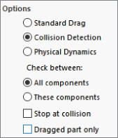
FIGURE 17.9 The Collision Detection option activates other options.
You can use Collision Detection to find collisions caused by dynamic assembly motion (dragging parts on the screen with Move Component) using all the parts in the assembly (All Components) or just selected components (These Components). Obviously, there is a performance (speed) cost to calculating collisions for all parts, so especially for larger assemblies, you should limit the parts used in Collision Detection if possible.
You can also set an option that will stop motion at a collision, which will help you visualize more realistic motion of the mechanism.
The Dragged Part Only option calculates interferences only for the dragged part with those around it.
Activating Collision Detection also activates other options in the Advanced Options panel:
- Highlight Faces: When faces collide, they highlight.
- Sound: When parts collide, you will hear a sound.
- Ignore Complex Surfaces: Faces that are created by loft, boundary, or other complex methods are more time-consuming when calculating interferences. To prevent diminished performance these types of faces can be ignored.
Using Physical Dynamics
The name Physical Dynamics may be a bit misleading. It is essentially unconstrained, free motion, and collision of parts where the parts interact to some extent. It is not any sort of real analytical dynamics. Physical Dynamics does not take into account initial velocity or momentum.
You cannot use Physical Dynamics with Dynamic Clearance. The only adjustment with it is a sensitivity adjustment that controls the resolution of the reactions. Because it is a live tool (all the reactions happen in real time as you drag parts on the screen), calculation speed is a factor.
Physical Dynamics is very useful if you need to find out if a component can be installed in or removed from a confined space. One of my customers modeled an engine in place and wondered if it could actually be installed through the narrow window on-site. I used Physical Dynamics to test the route and guide the engine out.
Using Sensors
 Sensors in SolidWorks keep track of several measurable values and notify you when a value deviates from high and low limits you can specify. You can use sensors in both parts and assemblies. The types of sensors available in assemblies are
- Simulation Data: Select one of a number of common simulation results to act as a trigger. (A simulation study must be available, so this sensor type is not available in SolidWorks Standard—you must have Simulation installed, licensed, and running for this to work.)
- Mass: When the mass satisfies a certain relation, the sensor displays a flag.
- Volume: When the volume satisfies a certain relation, the sensor displays a flag.
- Surface Area: When the surface area satisfies a certain relation, the sensor displays a flag.
- Dimension: You can use reference dimensions or driving dimensions, including dimensions calculated by equations.
- Interference Detection: SolidWorks looks for the interference of static parts in assemblies.
- Measurement: Any value you would normally take from the Measure tool can be tracked.
- Proximity: If you establish a sensor location, direction, and acting distance, the sensor returns a True value if a selected part passes through that sensor.
To add a sensor to an assembly, you must first have the Sensors folder in the assembly FeatureManager, as shown in Figure 17.10. FeatureManager If it is not there, you can activate it at Tools ➢ Options ➢ FeatureManager and make sure the Sensors folder is set to Show.
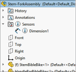
FIGURE 17.10 Activating the Sensors folder in the FeatureManager
To add a sensor, right-click the Sensor folder at the top of the assembly FeatureManager and select Add Sensor. Sensors can also be added through the Measure Tool interface. The Sensor PropertyManager is shown in Figure 17.11, with the sensor-type drop-down list expanded.
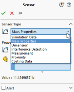
FIGURE 17.11 Adding a sensor to an assembly
After you have selected a type of sensor to add to the assembly, you then select the parts affected, set the options, and set the alert. The alert shows a notification balloon if the value returned by the sensor matches the expression you establish in the Alert panel of the Sensor PropertyManager.
For example, when the reference dimension shown in Figure 17.12 changes and becomes less than a certain value, SolidWorks displays an alert on the Sensors folder.
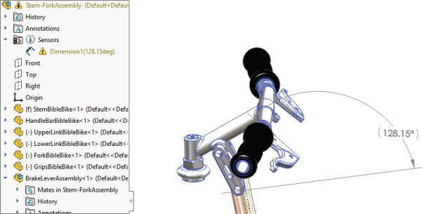
FIGURE 17.12 Sensors display alerts when an established value meets established criteria.
Selecting Components
In the SolidWorks Tools menu for assemblies, in addition to the normal selection methods such as Box, Lasso, Select All, there is an entry called Component Selection that offers a wide range of methods, as shown in Figure 17.13. You can also access these tools by expanding the flyout toolbar from the Select icon in the standard toolbar or other places it is used, such as the Title Bar toolbar.
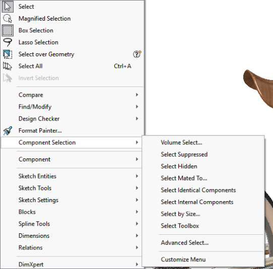
FIGURE 17.13 Selecting a Component Selection method in the SolidWorks Tools menu
SolidWorks does not have icon-driven activations for these tools, but they are available in the Customize ➢ Keyboard interface so you can make hotkey shortcuts to them.
Selecting with a Volume
The Volume Select option has no dialog box or PropertyManager interface. The workflow for this command goes like this:
- Put the assembly into a view orthogonal to a rectangular volume that you would like to create to select parts of the assembly.
- Preselect items to determine where the rectangular volume starts. Preselecting a point makes the face of volume go through the point; preselecting a plane makes the face of the volume coincident with that face.
- Initiate the Volume Selection command through the menus at Tools ➢ Component Selection ➢ Volume Select. Then go on to step 4 even though nothing appears to happen—no interface, no change to the screen, no special cursor.
- With the cursor, drag a rectangle on the screen (as you would to box select items in a sketch). After you drag the rectangle, SolidWorks will display a temporary volume and change to an isometric view. If you draw the original rectangle in an isometric view, the rectangular volume will line up with the screen (not the standard planes), and SolidWorks will rotate the view somewhat to give you access to all three dimensions of the temporary volume. SolidWorks will display arrows on the volume so you can tug and pull the faces to position it to select parts.
- Use the arrows to resize the resulting volume on the screen, as shown in Figure 17.14. SolidWorks will select any part that is completely within the volume. The selection is made when the volume contains the part; you don't have to do anything to activate the selection. Clicking outside the volume will dismiss the temporary display of the volume, but it will retain the selection. While the selection is active, you can use the commands from the RMB menus as usual.

FIGURE 17.14 Sizing the selection volume
Selecting Suppressed Components
To select all the parts in an assembly that are currently suppressed, you can use the command available at Tools ➢ Component Selection ➢ Select Suppressed. This command does not have a toolbar button, but you can assign a hotkey to it through the Tools ➢ Customize ➢ Keyboard interface.
The only indication that parts have been selected is in the FeatureManager. After the parts are selected, you can use RMB options with the selection.
Selecting Hidden Components
You can select hidden components just as you would select suppressed components. Again, this command has no interface or toolbar icon, but it can be linked to a hotkey. Remember that to hide a part quickly, put the cursor over it and press Tab. To show the part, put the cursor where the part should be and press Shift+Tab.
Selecting Subassemblies
The easiest and most traditional way to select a subassembly is to select it from the FeatureManager. You can also right-click any component in the graphics area and select the Select Subassembly option, and SolidWorks will display the assembly context toolbar. Subassemblies can also be selected through the Breadcrumbs interface because the current selection, such as a face, is identified by breadcrumbs as being part of a feature, body, part, subassembly, and so on in the current assembly.
Selecting Parts Mated to Another Part
The Tools ➢ Component Selection ➢ Select Mated To command, as the name suggests, selects any part mated to the part you select after you execute the command. There is no interface and no indication of what to do after you select the Select Mated To menu option, but for whatever part you click next, SolidWorks selects all the parts mated to it.
Selecting Identical Components
Select Identical Components can be activated with either preselection or post-selection methods. With post-selection, it uses a PropertyManager to prompt you to select a component. With preselection, there is no PropertyManager. The identical components are highlighted in the FeatureManager without a count.
Selecting Internal Components
The criteria for what SolidWorks means by “internal components” are not well spelled out. If you run this selection method on the Bike model, it selects a couple of parts that I would not consider to be strictly internal parts (parts under the seat and the small chain-ring on the crank). You may have to experiment with this tool to get the results you expect.
Selecting Toolbox Parts
The tool found at Tools ➢ Component Selection ➢ Select Toolbox selects all the Toolbox parts in an assembly, including parts at different levels in subassemblies.
Using the Advanced Select Options
Advanced Select has been around for a very long time in the software, but it has seen only limited use. It used to stand alone as the only advanced selection method, but now with all the options under the Component Selection heading, it has lots of company.
The interface used for Advanced Select is very old dialog-box style rather than the newer PropertyManager type of interface to which the more commonly used tools have been updated. Figure 17.15 shows the Advanced Component Selection dialog box.
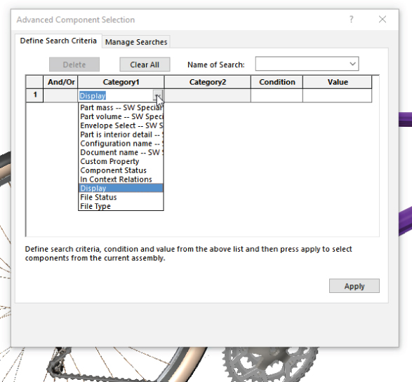
FIGURE 17.15 Using the Advanced Component Selection dialog box
You can use the criteria in the Advanced Component Selection dialog box to set up, save, and reuse queries (searches) based on special categories, conditions, and values. Figure 17.15 shows an example of setting up a search where the display is Shaded With Edges. Clicking the Apply button runs the search and selects the appropriate parts in the FeatureManager.
In this example, Category 2 would be used if Category 1 were File Status; Category 2 could be Read Only, Write Access, User With Write Access, Needs Save, or Out Of Date. The Condition options would be Is, Is Not, Contains, Does Not Contain, and so on.
Selections can be reused by using the Save Selection option, which is available through the RMB, which adds an entry to a folder in the FeatureManager.
Selecting by Size
The Select By Size option allows you to dynamically move the slider and see the parts that are under a certain percentage of the overall assembly size. Figure 17.16 shows the interface used to facilitate this selection. Components that meet the requirement are shaded blue. The dialog also tallies how many parts meet the criterion. Clicking OK leaves the components selected for whatever you choose to do next.
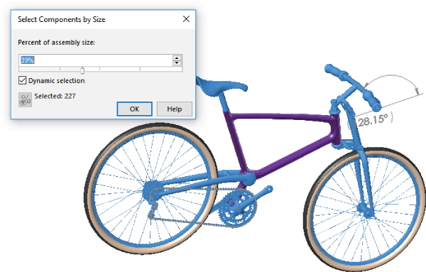
FIGURE 17.16 Selecting components by size
Reading Assembly Performance Evaluation Results
 The Assembly Performance Evaluation (formerly AssemblyXpert) tool provides information about assemblies. It gives statistics about parts, mates, resolved and lightweight components, subassembly depth, and other information. It may offer suggestions for things you might consider to improve assembly performance. The AssemblyXpert presents information in three status categories, displayed on the left side of the AssemblyXpert window:
 Passed
 Warning
 Information Only
A sample Assembly Performance Evaluation result window is shown in Figure 17.17.
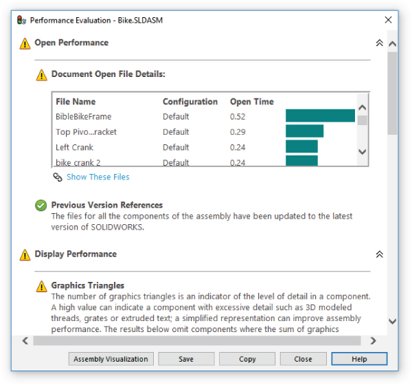
FIGURE 17.17 Assembly Performance Evaluation results can help you discover issues with slow assembly performance.
Assembly Performance Evaluation results are meant to help you speed up the performance of your assemblies by combining them with your knowledge of best practices. Assembly Performance Evaluation will never simply tell you what to do, but it might suggest you use Large Assembly mode, or it might tell you that 386 mates are evaluated when the assembly is rebuilt (which, along with performance problems and best practice knowledge should tell you that you might want to do something to minimize mates at this level of the assembly).
You should also consider using Assembly Performance Evaluation in conjunction with SolidWorks Rx, which can point out many system-level issues.
Using Defeature
 Defeature works in both parts and assemblies. It also works on both imported and native data. The purpose of this tool is to remove geometrical detail to improve performance and security when sharing data. The output of this function can be internally stored simplified geometry or simplified geometry sent to an external file or to 3D Content Central. (3DCC.com is the SolidWorks online sharing library for commonly used data.)
In parts, Defeature removes small features, or selected features, and leaves a folder at the top of the FeatureManager, as shown in Figure 17.18. The Defeature folder is associated with a “dumb” featureless, imported body stored in the file as a separate body. You can save these from the RMB menu for the Defeature folder in the FeatureManager.
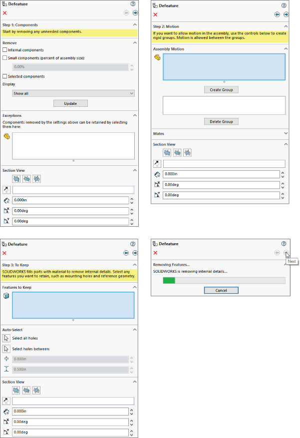
FIGURE 17.18 Defeature in parts
Defeature in the assembly uses a PropertyManager that has several steps:
- The Components step enables you to remove components, simplifying the defeatured assembly. You can allow SolidWorks to use an automatic method, or you can make the selections yourself.
- The Motion step enables you to group the remaining parts into groups that work like subassemblies for the purpose of motion.
- The To Keep step defeatures individual parts, filling in holes, removing small features, and so on.
- The Removing Features step of the process waits for SolidWorks to make all the changes you have asked it to do. This may take some time, depending on your computer and the assembly you are defeaturing.
Using the Hole Alignment Tool
 You can find the Hole Alignment tool through the menus at Tools ➢ Hole Alignment or on the Evaluate tab of the CommandManager. Hole Alignment is a feature-based evaluation tool. It detects misalignment (defined as centerlines that are more than a given distance from one another that you specify yourself) of Hole Wizard holes, simple holes, and extruded cylindrical holes. Figure 17.19 gives a look at the interface of the Hole Alignment tool.
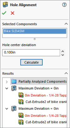
FIGURE 17.19 Using the Hole Alignment PropertyManager
This tool does have some limitations, which are mostly in the kinds of holes for which it can detect misalignment. The unsupported hole types are as follows:
- Multiboundary extrudes (multiple circles in a single sketch used for an extruded cut)
- Imported geometry
- Geometry created with any of the following:
- Move Face
- Move/Copy Body
- Split Part
- Mirror Body
- Mirror Part
- Mirror Component
- Pattern Body
- Insert Part
This list excludes many potential sources for error, and it doesn't leave many items of consequence. If you misalign holes using sketches or Hole Wizard holes, you have other problems.
The Bottom Line
SolidWorks packs lots of powerful and useful tools into the assemblies environment. Even if you are an experienced user, it pays to look through the list now and then because new functions are added frequently, or you may have a new use for an old tool.
- Master It Open the assembly called
Bike.sldasmfrom the downloaded materials for this chapter. Use each of the tools in the Tools ➢ Component Selection list to practice selecting parts in the assembly:- Volume Select—Drag a rectangle and then drag it to create a solid volume.
- Select Suppressed
- Select Hidden
- Select Mated To
- Select Identical Components
- Select Internal Components
- Select By Size
- Master It Use Advanced Select to select any components where the configuration name is not Default. Then invert the selection (RMB on a highlighted item, and it should be the first selection in the list), and then suppress all of the nonconfigured items.
- Master It Use one of the selection methods to select multiple components. Save the selection as a Selection Set.