Chapter 36
Creating Weldments and Weldment Drawings
Weldments are specialized parts that are similar in some ways to sheet metal parts. They are identified as a special kind of part by a Weldment feature in the FeatureManager, and you use a special set of tools to create and edit them. The specialized part enables specialized functionality such as cut lists, special body trimming functions, and gap creation between bodies.
Weldments in SolidWorks are built on structural profiles along sketch entities in a multibody part environment. Weldment members can be straight or curved, you can make them using standard or custom profiles, and you can build them from both 2D and 3D sketches. A cut list within the multibody part keeps track of the length of each profile that is needed to fabricate the weldment.
You can use weldments for round or rectangular tubular structures, structures made from channels, flanged sections, standard or custom shapes, gussets, and end caps. They can also represent weld beads in the part. You can also use weldments to create structures that are bolted together, structural aluminum extrusion frames, vinyl window frames, and wooden frames and structures, and you can put them into assemblies with other parts such as castings, sheet metal, and fabricated plates.
Sketching in 3D
 The 3D sketch is an important tool for creating weldments (and many other features) in SolidWorks. Structural frames are a large part of the work that's typically done using weldment functionality, and frames are often represented as 3D wireframes. You can represent 3D wireframes with a combination of 2D sketches on different planes, with a single 3D sketch, or with a combination of 2D and 3D sketches. If you have confidence in your ability to use 3D sketches, then that's the best way to go. 3D sketches can be challenging, but they're manageable if you know what to expect from them.
Navigating in 3D Space
When drawing a line in a 3D sketch, the cursor and origin initially look like those shown in Figure 36.1. The large red origin is called the space handle, with the red legs indicating the active sketching plane. Any sketch entities that you draw lie on this plane. The cursor also indicates the plane to which the active sketching plane is parallel. The XY graphic shown in Figure 36.1 doesn't mean that the sketch is going to be on the XY plane, just parallel to it.
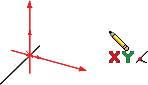
FIGURE 36.1 The space handle and the 3D sketch cursor
Pressing the Tab key causes the active sketching plane to toggle between XY, YZ, and ZX. The active sketching plane indication doesn't create any sketch relations; it just lets you know the orientation of the sketch entities that are being placed. If you want to create a skew line that isn't parallel to any standard plane, you can do this by sketching to available endpoints, vertices, origins, and so on. If there are no entities to snap to, then you need to accept the planar placement, turn off the Line tool, remove any automatic relations, rotate the view, and move one end of the sketch entity in a different plane.
An excellent tool to help you visualize what's happening in a 3D sketch is the Four Viewport view. This view divides the screen into four quadrants, displaying the front, top, and right views in addition to the trimetric or isometric view. You can sketch in any of the viewports, and the sketch updates live in all the viewports simultaneously. This arrangement is shown in Figure 36.2. You can easily access the divided viewport screen by clicking buttons on the Standard Views toolbar. You can also manually split the screen by using the splitter bars at the lower-left and upper-right ends of the scroll bar areas around the graphics window.
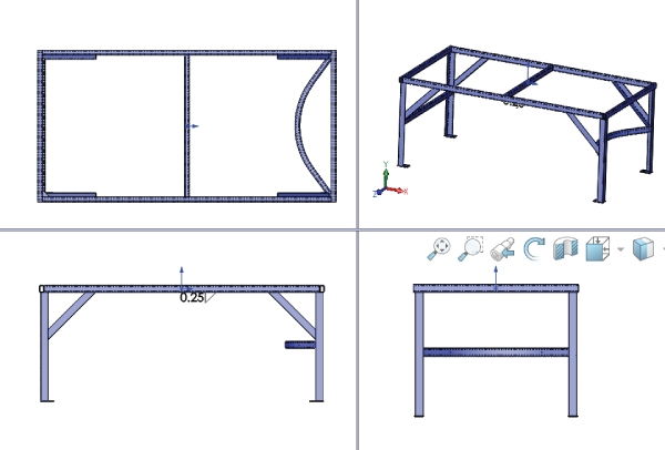
FIGURE 36.2 The Four Viewport view
When you move unconstrained entities in a 3D sketch, they move in the plane of the screen. You can use this to your advantage to create or edit lines in 3D space, but it can also lead to unexpected results. When you view the sketch at an angle, move it, and then rotate the view, you may notice that the sketch has shot off into deep interplanetary space. This is another reason for using the Four Viewport view, which enables you to see what's going on from all points of view at once, thereby avoiding any surprises.
Understanding Sketch Relations in 3D Sketches
Several relations are available in 3D sketches that aren't found in 2D sketches, such as AlongX, AlongY, AlongZ (which act as replacements for horizontal and vertical), and OnSurface.
Relations in 3D sketches are not projected as they are in 2D sketches. For example, an entity in a 2D sketch can be made coincident to an entity that's out of plane. This is because to make the relation, the out-of-plane entity is projected into the sketch plane, and the relation is made to the projection. In a 3D sketch, “coincident” means coincident, with no projection.
Keep in mind that solving sketches in 3D is more difficult than it is in 2D. You'll see more situations where sketch relations fail or flip in the wrong direction. Angle dimensions are particularly notorious in 3D sketches for flipping direction if they change and go across the 180-degree mark. When possible, you should work with fully defined sketches and be careful (and conservative) with sketch relations.
For example, the sketch shown in Figure 36.3 cannot be fully defined without also overdefining the sketch. The main difficulty is that the combination of the tangent arc and the symmetric legs of the end brace cannot be located rotationally, even using the questionable reliability of 3D planes that are discussed next. The only workable answer to this problem is to create a separate 2D sketch on a real 2D sketch plane, where the plane is defined by the elements of the 3D sketch.
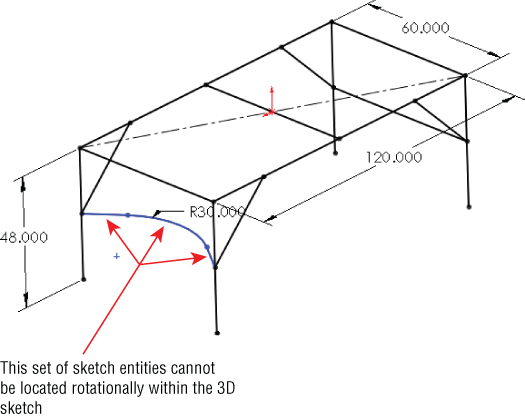
FIGURE 36.3 Three-dimensional sketches may be difficult to fully define.
Creating Planes in Space
 It's possible to create planes directly inside 3D sketches. These planes are defined by constraints and selections rather than selecting a type of method to define a plane. Sketches can be created on these planes and move with the planes. Having planes in the sketch also enables planar sketch entities such as arcs and circles in 3D sketches.
Unfortunately, you must watch out for many things with 3D planes. Be aware that they don't follow their original definition like normal reference-geometry-type planes. Planes inside 3D sketches act more like sketch entities in that if they are underdefined, they can move around inside the sketch. Watching sketch planes move in a sketch is very unsettling for most SolidWorks users. Figure 36.4 shows the PropertyManager interface for creating 3D planes; however, keep in mind that the plane doesn't maintain the original relation to these initial references. The parent-and-child relations that SolidWorks users are used to are suspended for this one function, or they work in the reverse from what you normally expect.
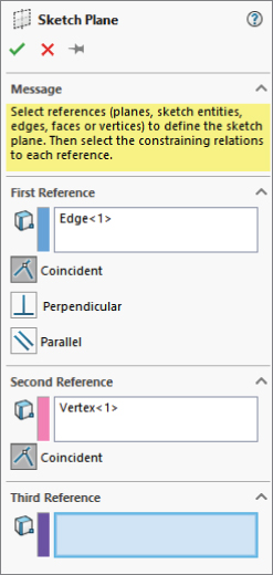
FIGURE 36.4 The PropertyManager for creating 3D planes
A 3D plane cannot be fully defined unless some sketch geometry on the plane is in turn related to something else. Limited types of sketch relations can be applied directly to the actual plane. Horizontal and vertical relations cannot be applied directly to the plane to orient it. Horizontal and vertical relations of entities on the plane are relative only to the plane and not to the rest of the part; therefore, making a line horizontal on the plane doesn't mean anything when the plane rotates (which it's free to do until it's somehow constrained to prevent this).
Beyond this, when a plane violates a sketch relation, the error isn't reported, which severely limits the amount of confidence that you can place in planes that are created in this way. The biggest danger is in the plane rotating, because that's the direction in which it is most difficult to fully lock down. The best recommendation here is to create reference sketch lines with relations to something stable, preferably outside of the 3D sketch.
If you choose to use 3D planes, you can activate them for sketching by double-clicking a plane. The plane is activated when it displays a grid. You can double-click in an empty space to deactivate the plane and return to regular 3D Sketch mode. The main thing that you give up when abandoning 3D sketch planes is the ability to use the Dynamic Drag options when all loft or boundary sketches are made in a single 3D sketch.
Limiting Path Segments
Some of the path segments that are allowed in 3D sketches can be used only if you sketch them on a plane. These entities include circles and arcs, and can include splines, although splines aren't required to be on a plane. To sketch on a 3D plane (a plane created within the 3D sketch), you can simply double-click the plane.
Some sketch entities and tools exist that you cannot create or use inside a 3D sketch, even if a sketch plane is activated. They include the following:
- Autodimension
- Fully Define Sketch
- Modify Sketch
- Sketch Slot
- Ellipse
- Polygon
- Dynamic Mirror
- Offset Entities
- Sketch text
- Sketch Picture
To sketch on a standard plane, planar face, or reference geometry plane, you can Ctrl+click the border of the plane with the Sketch Entity icon active or double-click the plane. The space handle will move, indicating that newly created sketch entities will lie in the selected plane.
Using Dimensions in 3D Sketches
 Dimensions in 2D sketches can represent the straight-line distance between two points, or they can represent the horizontal or vertical distance, depending on the position of the cursor when you place the dimension. In 3D sketches, dimensions between points are always the straight-line distance. If you want to get a dimension that's horizontal or vertical, you should create the dimension between a plane and a point (the dimension is always measured normal to the plane) or between a line and a point (the dimension is always measured perpendicular to the line). For this reason, reference sketch geometry is often used freely in 3D sketches, in part to support dimensioning.
This is one of the differences between 2D and 3D sketches that users find difficult to manage. If you're used to visualizing dimensions within 2D sketches, direction-controlled dimensions in 3D sketches can be difficult to visualize and even more difficult to create.
Using the Weldment Tools
Like the Sheet Metal tools, the Weldment tools in SolidWorks are specialized to enable you to create weldment-specific features in a dedicated environment. Everything starts from a sketch or set of sketches representing the wireframe of the welded structural members.
Using the Weldment Feature
 The Weldment button on the Weldment toolbar simply places a weldment placeholder in the FeatureManager. This placeholder tells SolidWorks that this part is a special weldment part—much in the way that the Sheet Metal feature in sheet metal parts is a placeholder—and denotes a special part type. The Weldment feature moves to the top of the tree, regardless of when you create it in the part history. If you don't create a Weldment feature manually, then one is automatically created for you and placed at the top of the tree when the first Structural Member feature is created. Structural members are discussed in the next section.
This feature offers only a few special default settings: You can set custom properties that transfer to all cut-list items that are created in the current part, and the Merge Result option is deselected by default in weldment parts. The ability to set custom properties is important when multiple weldments go together to make an assembly. To access the Custom Properties interface, shown in Figure 36.5, select the Properties option on the Weldment feature RMB menu.
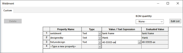
FIGURE 36.5 The Weldment Properties interface
The general workflow for creating weldment parts is as follows:
- Create a new part and insert a Weldment feature.
- Create a structural layout of 2D sketches, 3D sketches, or a combination of 2D and 3D sketches to represent a structure to be fabricated by cutting and welding structural shape stock.
- Ensure that you have a library with appropriate structural shape sketches, properties, materials, and so on.
- Make sure that you have allowed for sketch lines in the structural layout to represent a corner, centerline, or some other reference in the library structural shape sketch. This can greatly affect intersections between structural members.
- Assign structural shapes to individual lines in the structural layout. Be sure you understand the rules on using groups.
- Trim and miter intersections between structural members to suit your design.
- Add plate entities such as end caps and gussets.
- Add weld beads as needed.
- Place the weldment into an assembly, and add castings and sheet metal parts, as well as holes and fasteners to attach nonwelded components.
Introducing the Structural Member Feature
 A structural member is the basic building unit of weldments in SolidWorks. You can create a structural member by extruding or sweeping a profile along one or more path segments, and it may result in a single body or multiple bodies. The path segments may be in the form of 2D or 3D sketches.
When creating the sketch for the weldment, it's important to decide what the sketch represents. For example, does it represent the centerline of the structural elements or does it represent a corner? You can orient and position structural shape profiles relative to the frame sketch in several ways, with positioning at the shape centroid being probably the most intuitive for closed shapes and a corner being most intuitive for angle channels.
Figure 36.6 shows a single 3D sketch of a simple frame and a Structural Member feature in the process of creation. You must select the standard first, then the type, and finally the size. A limited number of profiles come with the software, and although you'll probably need to create some custom profiles, they're fortunately very easy to create.
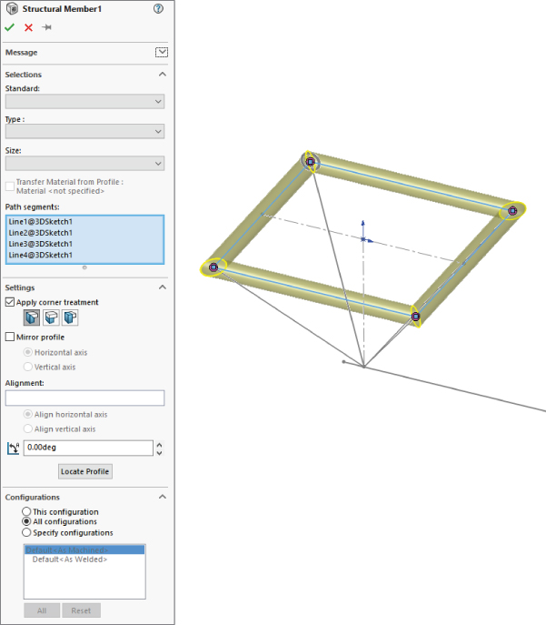
FIGURE 36.6 A 3D sketch of a frame
To access a large number of weldment profiles in various standards, open the Design Library and click the SolidWorks Content icon. Under that, the Weldments folder has several zip files containing weldment profiles. Ctrl+click an icon to download the file, and then extract the contents of the zip file to the library location you have established for your weldment profiles.
GROUPING SELECTED PATH SEGMENTS
The concept of groups is simple. You can organize selected path segments within a structural member feature into two kinds of groups: parallel or contiguous. A single structural member may have multiple groups.
Parallel groups contain parallel path segments that don't touch. Parallel groups also require that you select the structural profile before you can select more than one path segment.
Contiguous groups contain path segments that touch end to end, two segments at a time. A contiguous group cannot have one path segment intersect in the middle of another or more than two path segments intersecting at a corner.
Each group can have only a single orientation of the structural profile. For example, if each frame leg needs the profile rotated to a different orientation, you need to rotate the legs in four separate groups instead of all in a single group.
Given those requirements, if the frame shown in Figure 36.6 were to be created entirely from the same structural profile—say, ANSI (American National Standards Institute) inch, square tube, 3 × 3 × 0.025—it would require a minimum of five groups, as shown in exploded form in Figure 36.7. The file used to create this image is included in the download materials from the website under the name Weldment groups.sldprt.
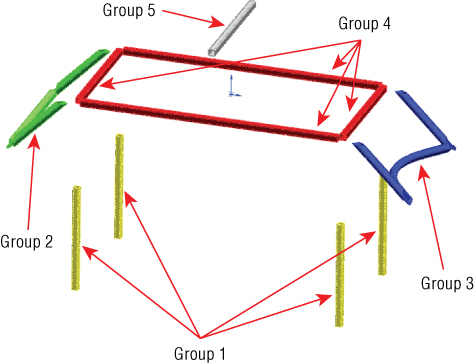
FIGURE 36.7 Using groups to create the welded frame
The main advantages of the groups functionality are that each member within the group is automatically trimmed to other members of the group, and you can control gaps within or between groups. The only trimming you need to take care of separately is the trimming between members of different groups.
LOCATING AND ORIENTING THE PROFILE
When you apply a profile to a path segment in a Structural Member feature, the profile must have some relationship to the path segment. The default point where the path “pierces” the profile is at the sketch origin. To change the pierce point, you can click the Locate Profile button at the bottom of the Structural Member PropertyManager, which zooms the view to present the profile sketch so you can select another sketch point to use as the pierce point. You can select any sketch point on the profile, including endpoints, sketch points, and virtual sharp points if they are present in the sketch.
Profile sketches are generally surrounded by several sketch points, which may seem unnecessary until you consider that you can use any of the points to position the profile. The Settings panel at the bottom of the Structural Member PropertyManager is shown in Figure 36.8 and displays a profile sketch with the interface.
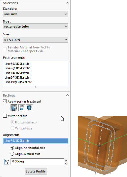
FIGURE 36.8 Locating the profile
In addition to locating the profile sketch, you can also rotate the profile using the Angle field in the Settings panel. This rotates all the bodies that are created by the Structural Member feature at the same time. In the example of the four-legged frame, if the legs are rectangular or circular, they can all be created in the same Structural Member feature because they're all rotated in the same way. However, if the legs are made from an asymmetrical shape such as an angle, then each leg needs to be made using a separate Structural Member feature, with each leg rotated differently.
USING DISJOINT SKETCH SEGMENTS
You can select disjoint sketch segments in a single Structural Member feature if they're parallel to the first segment and use the same profile height location and orientation. For example, in Figure 36.7, notice the four angled supports in the corners attaching to the legs. Because they're parallel in pairs, all four of these supports could not be made in a single group. Later in this section, when those path segments are actually used to place structural members, the additional requirement of using an angle profile will mean that each profile needs to be rotated differently from the other profiles and, as such, cannot be used in a single group.
USING CUSTOM PROFILES
Most of the custom profiles that you will need may be simply new sizes of existing profiles. You can easily create a custom profile by opening an existing profile, editing it, and saving it under a different name using the Save As command. You can also use configurations in the library part to create multiple sizes of the profiles, which can then be selected for use in weldment parts.
Other sources for custom profiles include 3D Content Central, which has a large number of erector-set aluminum extrusion profiles and the accessory hardware for those systems. Toolbox also has a Structural Steel sketch generator, shown in Figure 36.9, which enables you to generate most standard shapes. If you have Toolbox installed on your system, you can find this tool in the Toolbox menu.

FIGURE 36.9 The Structural Steel sketch generator interface
Weldment profiles are great candidates for storing in your special library folder, separate from the SolidWorks installation directory. To establish this library location, you can choose Tools ➢ Options ➢ File Locations ➢ Weldment Profiles. Also keep in mind that if you share design duties with other users, either the library location should be shared among users on a network or the libraries should be copied to each user's local library. You can also share library data through a Product Data Management, or PDM, program.
If you are creating completely new custom profiles, remember that when locating the profile relative to the path segments, you can use any sketch point. As a result, you should provide ample selections for pierce points. Virtual sharps function well around filleted corners, as well as sketch points at the centroid of a shape.
In addition to sketch geometry, the library part files should also contain custom property information about the structural shape, such as part number, supplier, material, and so on. This information propagates to the cut list.
ADDING CORNER TREATMENTS
Any intersection of sketch lines at mutual endpoints within a single group, except as noted in this section, creates a situation that requires that the corners be cut to match. Figure 36.10 shows an example of the options available when lines meet at right angles. Notice that within a group, you have the option to set a weld gap at the intersections.

FIGURE 36.10 Corner Treatment options
To access the toolbar with the Corner Treatment options, you can click the pink dot at the intersection of the path segments. The default Corner Treatment settings are found in the Structural Member PropertyManager, but you may need to adjust them individually.
Two situations don't require corner treatments. The first situation is when a line intersects another line at some location other than an endpoint in the same Structural Member feature—for example, a support meeting the main member in the middle. In this situation, the member that ends in the middle of the other member is trimmed to a butt joint. The second situation is when an intersecting member is created by a later Structural Member feature. You deal with this situation by using the Trim/Extend function, which is described later in this chapter.
USING ARC SEGMENTS
When arc sketch segments are part of the selection for a Structural Member, a Merge Arc Segment Bodies option appears after the selection box in the Selections panel. This means that any tangent arc segment will be joined to the entities to which it's tangent, but any nontangent entities will create separate bodies.
Figure 36.11 shows a tangent arc in the curved leg brace, along with the Merge Arc Segment Bodies option in the PropertyManager.
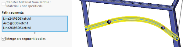
FIGURE 36.11 A tangent arc segment used in a Structural Member feature
If the Merge Arc Segment Bodies option isn't selected, then a separate body is created for arc segments. The Merge Arc Segment Bodies option applies to the whole feature and cannot be set selectively for individual arc segments within the selected sketch entities; it's either selected for all or deselected for all. If some arc segment bodies are merged and others are not, then you should create separate Structural Member features.
It's also a curious limitation that only one arc may be selected if the selected path segments are disjointed. For example, you cannot select the two arcs for two J-shapes that don't touch in the same Structural Member feature. The obvious workaround is to create two separate groups.
PATTERNING BODIES AND SKETCHING WITH SYMMETRY
Bodies created by the Structural Member feature can be patterned and mirrored. Remember that there's a difference between patterning features and patterning bodies. The Move/Copy Bodies feature is also appropriate for creating bodies to be used in the weldment, although the Structural Member feature doesn't create them directly.
This is mentioned here to emphasize the point that sketching with symmetry is still important, although it's more difficult with 3D sketches than with conventional 2D sketches. Symmetry in a 3D sketch can be used only when a plane is activated, and you can activate regular reference geometry planes, not just 3D sketch planes. This is also mentioned because in larger weldments (or when using slower computers), performance may be an issue, and mirroring or patterning bodies is certainly a performance enhancement over building parametric features.
CREATING CONFIGURATIONS
When you start creating a weldment, SolidWorks may automatically create a derived configuration, depending on the setting at Tools ➢ Options ➢ Document Properties ➢ Weldments ➢ Create Derived Configurations. Both configurations are named Default, but they have different descriptions. The parent configuration description is As Machined, and the derived, or indented, configuration description is As Welded.
This arrangement holds true for any additional top-level configurations that you create in the part—they will all get the description As Machined and inherit an identically named derived configuration with the description As Welded. These configurations are meant to help you create drawings where the raw weldment is distinguished from the weldment after it has been machined, ground, and drilled.
Using the Trim/Extend Feature
 In situations where you must create multiple Structural Member features, thereby creating intersecting bodies, you must deal with the interferences using the Trim/Extend feature. An example of this is shown in Figure 36.12. The legs and braces shown are all being trimmed by a single face on the bottom side of the rectangular section of the frame, where a small arrow will appear.
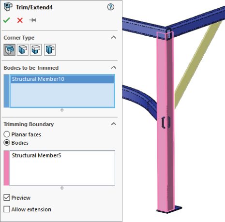
FIGURE 36.12 Using the Trim/Extend feature
Bodies can be trimmed by planar faces or other bodies. Bodies can also be trimmed before they are mirrored or patterned. Although trimming with faces is faster, it may not give the same geometrical results.
The Extend option enables either trimming or extending, as appropriate. If the Extend option isn't selected, then trimming is the only action available.
Using the End Cap Feature
 The End Cap feature closes off an open-ended structural member. You can add multiple end caps in a single End Cap feature. The PropertyManager and the end product are shown in Figure 36.13.
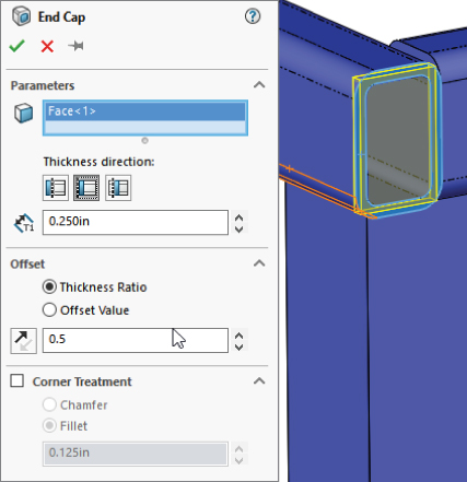
FIGURE 36.13 Using the End Cap feature
The end cap using the Outward option sits on the outside face of the member and overlaps the thickness of the member by the inverse of the thickness ratio that's applied in the Offset panel. If the Use Thickness Ratio option is turned off, it functions as an offset from the outer faces of the member from which it is created. When this option is turned on, the thickness ratio can range from zero to one. For a value of zero, it's flush with the outer faces of the member, and for a value of one, it's flush with the inner faces of the member. Using the Inward option, the cap fits inside the hole in the member.
Working with the Gusset Feature
 The Gusset feature creates a three-, four-, or five-sided gusset in a corner between structural members, as shown in Figure 36.14. You can place the gusset at specific locations along the edge in the corner, or you can offset it by a specific dimension in a specific direction by using the settings in the Parameters panel. You can control the size and thickness of the gusset in the Profile panel. There's no sketch for this feature type; it's simply created from the parameters that you enter in the PropertyManager interface. Again, if you need to make multiple Gusset features in succession, you can use the pushpin icon to keep the interface displayed until you close it by clicking the red X icon.
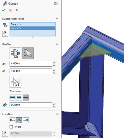
FIGURE 36.14 Using the Gusset feature
Using Nonstructural Components
Nonstructural components are frequently needed in weldments and include items such as feet, plates, brackets, mounting pads, and castings. Simpler items that can be easily modeled in place can be modeled directly into the weldment part. You can also insert parts into the weldment using the Insert Part feature and move them into place by using dimensions or mates. In general, if any item is actually welded into the weldment, you should place it in the weldment part; however, items that are bolted on should probably be placed into an assembly. Of course, this probably depends more on your company's documentation standards, part-numbering standards, and assembly processes than on software capabilities.
When you’re modeling a plate using the standard Extrude feature, except that the Merge option is deselected by default. This ensures that nonstructural components that are manually modeled, such as this part, are created as separate bodies and not merged together with the existing structural items.
Using Sub-Weldments
From a modeling point of view, sub-weldments are generally used for either organizational or performance reasons to group together elements of a weldment or to break a larger weldment into more manageable pieces. This is in much the same way that subassemblies are created for the same purposes within larger assemblies. From a fabrication point of view, sub-weldments are also used to break a large weldment into pieces that can be transported or handled.
To create a sub-weldment, you can select several bodies from the cut list and then select Create Sub-Weldment from the RMB menu. (You can also select the bodies from the graphics window if you use the Select Bodies selection filter.) This creates a separate folder for the sub-weldment bodies. You can then right-click the Sub-Weldment folder and select Insert Into New Part.
Working with Cut Lists
 The cut list that's maintained in the model FeatureManager is simply a replacement for the Solid Bodies folder. It has most of the same functionality as the Solid Bodies folder, as well as a few additional items. The Cut List folder symbol in the FeatureManager can appear in two potential states; these symbols are shown in the left margin. When the cut list requires an update, the top image is shown; and after the update has been performed, the bottom image is shown. Cut lists are updated automatically when you access a drawing that uses the cut list, but you can also update them manually through an RMB option or by the forced rebuild, Ctrl+Q.
You can access the Update command by right-clicking the Cut List folder and selecting it from the RMB menu. Figure 36.16 shows the result of the update. The weldment solid bodies are broken down further into subfolders that reflect quantities of identical bodies. Notice that the weld beads at the bottom of the list are not in a folder.
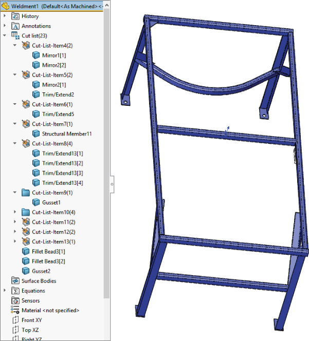
FIGURE 36.16 The cut list in the model FeatureManager
Using Cut-List Properties
In addition to the custom properties for the document, SolidWorks weldments also utilize Cut-List Properties. You can access Cut-List Properties by right-clicking a Cut List Item folder (other than the top-level Cut List folder) at the top of the FeatureManager and selecting Properties. The Cut-List Properties may not be available for a newly created weldment until you have updated the cut list (right-click the top-level Cut List icon and select Update).
Figure 36.17 shows the Cut-List Properties dialog box, which allows users to enter data such as length and material for BOMs and cut lists.
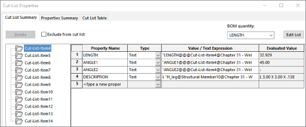
FIGURE 36.17 Use the Cut-List Properties dialog box to enter relevant data for BOMs and cut lists.
Notice the Properties Summary tab, which enables you to look at each property and see the value for each cut-list item. This is where you would select a property such as Description, assign descriptions for each cut-list item, and then go on to the next property—say, Material—and assign values for that property.
The Cut List Table tab shows you a preview of the cut list and enables you to use cut-list templates that might have different default columns established. Figure 36.18 shows the Cut List Table tab of the Cut List Properties dialog box.
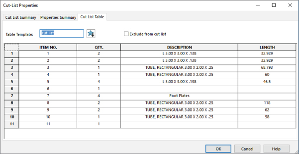
FIGURE 36.18 The Cut List Table tab previews the cut list for you and gives you the opportunity to edit values in the table.
As Figure 36.18 shows, you may need to enter information for items added to the weldment such as end caps or gussets. Cut-list properties are also added when you insert a bounding box for nonstructural members.
Excluding and Reordering Cut-List Items
To exclude a feature in the FeatureManager from the cut list, you can select Exclude From Cut List from the feature's RMB menu. The next time the cut list is updated, the members that were created by that feature will be listed at the bottom of the Cut List folder with the weld beads. To include the item again in the cut list, select Include In Cut List from the feature's RMB menu and update the cut list again. Figure 36.19 shows a folder that has been excluded from the cut list.
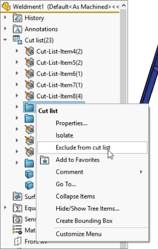
FIGURE 36.19 Excluding an item from a cut list
Only entire Cut List folders can be eliminated from the cut list, not individual bodies. To reorder items in the cut list, just drag and drop the folder to where you want it to be in the list.
Using Weld Beads and Fillet Beads in Weldments and Assemblies
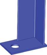
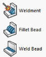 The icons for Weldment, Fillet Bead, and Weld Bead look very similar. The Weldment tool is used to proclaim the part as a Weldment part. The difference between a fillet bead and a weld bead is that the Fillet Bead feature creates actual solid geometry, which shows up in a weldment part as a feature, while the Weld Bead feature creates a cosmetic representation of a weld bead. Figure 36.20 shows the Fillet Bead features in the FeatureManager and the actual fillet bead between a plate and a structural member.
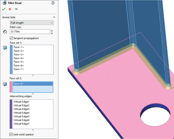
FIGURE 36.20 The Fillet Bead feature in the FeatureManager and on the part
To create a weld in an assembly, you still use the Weld Bead tool. The Weld Bead feature produces a cosmetic display of a weld and keeps track of it in a folder at the top of the assembly FeatureManager or the Weldment Part FeatureManager.
Figure 36.21 shows the Weld Bead PropertyManager and the preview it applies to a weldment part.
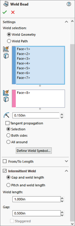
FIGURE 36.21 The Weld Bead feature shows up in the Weld folder and as a cosmetic display on the part.
The Weld Bead feature doesn't show up in the part or assembly FeatureManager as a feature (even though you access the command at Insert ➢ Assembly Feature ➢ Weld Bead), and it doesn't create geometry that adds mass. It does produce a cosmetic weld bead on the part, and it creates a new folder in the FeatureManager right below the Annotations folder. The entries in the folder show how many weld beads of what length are applied to the entire weldment. Fillet beads add nothing to the Weld folder. As a result, the type of information you need to have in your model will help you determine if you want to use the Fillet Bead or Weld Bead feature. If you need to show welds in an assembly, you have to use the cosmetic display of weld beads.
The Weld Bead PropertyManager also gives you the option to define the ANSI weld symbol before the feature is complete. The interface for defining the weld symbol is shown in Figure 36.22. Use the Define Weld Symbol button in the Settings panel of the Weld Bead PropertyManager to access this interface.

FIGURE 36.22 Assigning a weld symbol in the Weld Bead feature
Creating Weldment Drawings
Weldment drawings have a couple of special features that distinguish them from normal part drawings. The first is obviously the cut list. Like a BOM in an assembly, you can place the Weldment Cut List on a drawing by choosing Insert ➢ Table ➢ Weldment Cut List. Figure 36.23 shows a sample cut list on a drawing. In this case, the blank rows represent nonstructural components: the footplates and the gusset. You can manually add data for these parts either directly into the table or by adding it to the properties of the corresponding folder in the cut list in the model document.
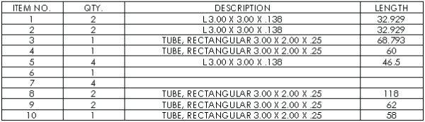
FIGURE 36.23 A cut list on a drawing
Figure 36.23 also shows an auto-ballooned isometric view of the entire weldment. This works the same way that assembly auto-ballooning works, and it corresponds to the cut list in the same way that the assembly corresponds to the BOM.
Weldment drawings can also include views of individual bodies. You can do this by making a relative view, selecting both faces from the same body, and then using the PropertyManager of the relative view in the window of the solid model to control whether the view shows the entire part or just selected bodies. The Relative View PropertyManager is shown in Figure 36.24.
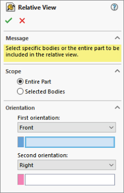
FIGURE 36.24 The Relative View PropertyManager
When you place a drawing view of a weldment, you can also link a cut list to a particular view. This might help you with putting multiple weldments on a drawing or laying out the process for fabricating a weldment, showing the weldment in various stages of completion.
To access the Relative View PropertyManager interface, follow these steps:
- Click the Relative View button on the Drawings toolbar, or choose Insert ➢ Drawing View ➢ Relative To Model.
- Right-click a blank space on the drawing sheet and select Insert From File. Browse to the part file.
- Identify the faces to be shown in the particular orientations, and specify whether the entire part or the selected bodies should be shown in the view.
Tutorial: Working with Weldments
This tutorial guides you through building a section of a tubular truss support. You can create many different types of weldments, from simple small-gauge frames to large architectural designs such as this one. This tutorial also helps you to navigate successfully through some 3D sketch functionality for creating fully defined sketches.
Follow these steps to learn about working with weldments:
- Open a new part. If you have Toolbox, activate it by choosing Tools ➢ Add-Ins ➢ SolidWorks Toolbox. If you don't have Toolbox, simply draw two concentric circles on the Front plane of a new part. The circles should have diameters of 10.02 inches and 10.75 inches. Alternatively, you can copy the library feature from the download material to a path such as
D:\Library\Weldment Profiles\Custom\Pipe\P-Pipe10in.sldlfp. - If you have Toolbox, choose Tools ➢ Add-ins ➢ SolidWorks Toolbox ➢ Structural Steel. If you don't have Toolbox, just select a shape from the installed SolidWorks library.
- Select ANSI Inch, P Pipe, P10. This profile has an inside diameter of 10.02 inches and an outside diameter of 10.75 inches. Click the Create button and then click Done.
- Use Custom Properties to add any properties that you want to have automatically added to the cut list.
- Remembering the techniques on library features, first close any open sketches, select the sketch from the FeatureManager, and then save the part as a Library Feature Part file to the location specified at the end of step 1.
- Choose Tools ➢ Options ➢ File Locations ➢ Weldment Profiles, and add your non-installation directory location to the list of folders. Alternatively, you can remove the Program Files location from the list and copy the files from that location to your own library location.
- Open another new part and open a new 3D sketch in the part. Double-click the Top (ZX) plane to activate it and click the Center Rectangle sketch entity.
- Draw a rectangle around the origin. The sketch should look like Figure 36.25. Apply an Equal relation to two adjacent sides of the rectangle, and dimension any of the lines as 120 inches.
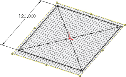
FIGURE 36.25 A centered rectangle in a 3D sketch
- Turn off the rectangle and double-click in a blank space to deactivate sketching on the Top plane.
- Activate the Line sketch tool and press Tab until the cursor indicates the XY plane.
- Draw a line from one corner of the square down, trying to avoid any automatic relations such as Coincident relations to other points and any AlongX, AlongY, or AlongZ relations. Connect the other three corners of the square with the free endpoint of the new line, as shown in Figure 36.26.
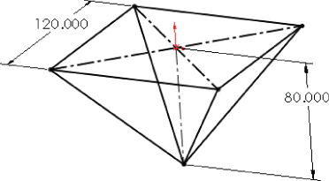
FIGURE 36.26 Adding lines
- Rotate the view slightly. Notice that the first line that you drew in step 10 and one other line are on a plane. Drag a right-to-left selection box around the point where the four lines converge, and assign an Equal relation to all the lines. This makes the shape into an upside-down pyramid.
- Drag the point. Notice that it moves up and down, although it seems a little erratic. Place a dimension between the point and the part origin. Notice that the sketch becomes overdefined and turns red and yellow. Theoretically, this combination should work, but SolidWorks doesn't accept it.
- Using the Display/Delete Relations tool, delete all the Equal relations that you just added to the part. It may be faster to select Undo from the File menu or to press Ctrl+Z.
- Draw a vertical construction line from the part origin to the point where the four lines meet, and assign this line an AlongY relation. Notice that the point drags much more smoothly. This is a good reason for using simpler relation schemes when possible. In this case, the four equal relations that had to be solved simultaneously are now replaced by a single relation that's easier to solve when you drag the sketch. Apply a dimension of 80 inches to the new construction line.
- Draw a new line from the point where the four lines come together AlongX in the positive X direction. Dimension this new line as 120 inches. The sketch should look like Figure 36.27.

FIGURE 36.27 The sketch after step 16
- Exit the sketch. Click the Structural Member toolbar button on the Weldments toolbar. In the Standard drop-down list in the Structural Member PropertyManager, select Custom. In the Type drop-down list, select Pipe. In the Size drop-down list, select P-Pipe10in. This is the name that corresponds to the way you saved the library feature part in step 5.
- In the Path Segments selection box, select the original four sides of the rectangle. In the Settings panel, make sure that the Apply Corner Treatment option is selected and that the End Miter icon is selected. This is shown in Figure 36.28. Accept the command when you are finished.
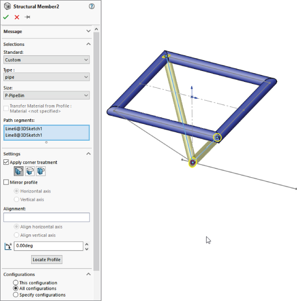
FIGURE 36.28 The Structural Member PropertyManager and the sketch after step 18
- Expand the Structural Member feature. Notice that the four bodies are listed under it. Click the Cut List folder to expand it. The bodies should also be listed there.
- Open the 10-inch Pipe library feature that you created at the beginning of this tutorial. Edit the two dimensions to subtract 2 inches from each dimension, and add a custom property description called Support Leg. Choose File ➢ Save As to save the library feature to the same location as the original, but with the filename
P-Pipe8in.sldlfp. - Initiate another Structural Member feature, this time selecting the 8-inch size of pipe from the Custom folder. In the Path Segments selection box, select two of the angled lines that go to opposite corners. Keep the feature open for the next step.
- Make a second group with the other pair of angled lines. Accept the feature when you are satisfied. The model should look like Figure 36.29.
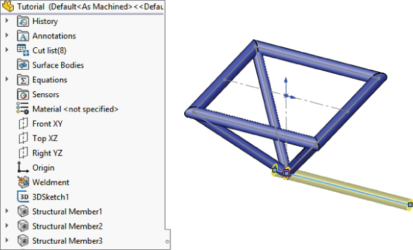
FIGURE 36.29 The model showing the features accepted in step 22
- Apply another Structural Member feature to the 10-foot (120-inch) section, again using the 10-inch-diameter pipe. Notice that this member isn't long enough to cut through the peak of the pyramid.
- Edit the 3D sketch and draw a 12-inch extension to the original line past the peak of the pyramid. Use an additional line rather than extending the existing one. Exit the sketch.
- Edit the Structural Member feature to add the new line.
- The four angled members need to be trimmed on both ends because they extend to the ends of the sketch entities rather than stopping at intersecting members. Initiate the Trim/Extend feature. Select the four angled members in the Bodies To Be Trimmed selection box. Select the four members created by the original rectangle as the Trimming Boundary, and make sure that the Bodies option is selected (as opposed to Face/Planar), as shown in Figure 36.30. Accept the feature when you are finished.
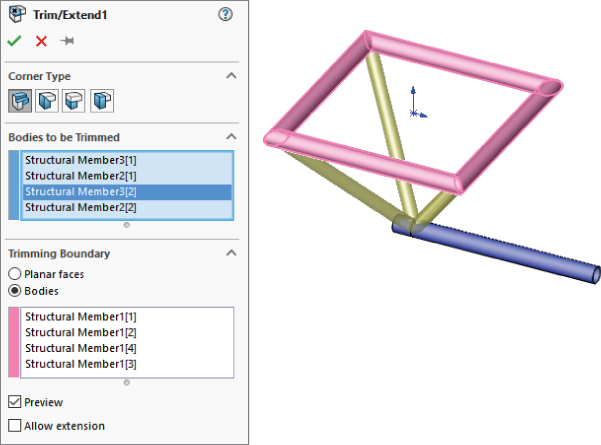
FIGURE 36.30 The model after step 26
- Create another Trim/Extend feature. This time, trim off the point end of the four angled members using the 10-inch horizontal pipe and the small segment as the trimming boundary. Half of the support structure has been modeled to this point.
- Create the rest of the support structure by mirroring the existing bodies. Create a Mirror feature using the free end of the 10-foot-long member as the mirror plane and selecting all the bodies in the Bodies To Mirror selection box. Don't select the Merge Solids option, because you'll need to merge solids manually. Click OK to accept the feature when it's set up properly. The PropertyManager for the Mirror feature is shown in Figure 36.31.
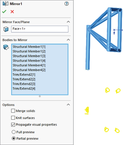
FIGURE 36.31 The PropertyManager for the Mirror feature in step 28
- Select the Combine feature (Insert ➢ Feature ➢ Combine), and set it to Add. Select the two 10-foot sections and the two smaller 1-foot sections to combine them into a single continuous body. Click OK to accept the feature. Also hide the 3D sketch.
- Right-click the Cut List folder and select Update. Figure 36.32 shows before and after images of the Cut List folder.
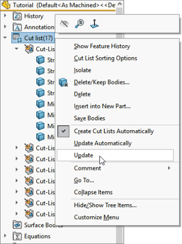
FIGURE 36.32 The Cut List folder in step 30
- Right-click the folder for the large-diameter cross member and select Properties. Change the Description field to read Support Pod Members.
- Use the Create Drawing From Part/Assembly button on the standard toolbar to make a drawing. Place the front, bottom, and isometric views, and then press the Esc key to quit placing views.
- Select one of the views and choose Insert ➢ Table ➢ Weldment Cut List. When the PropertyManager displays, select the options that you want and click OK. Then place the table.
- Click inside the bottom view, and from the Annotations toolbar, click Auto-Balloon. The finished drawing looks like Figure 36.33.
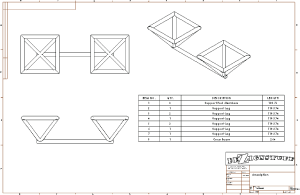
FIGURE 36.33 The finished drawing
The Bottom Line
Weldments are based on either a single 3D frame sketch or a set of 2D sketches, usually denoting the centerlines or edges of the various structural elements. This creates a special type of part in the same way that the Sheet Metal commands create a special type of part. Structural profiles are placed on the frame sketch to propagate and create individual bodies for the separate pieces of the weldment. Custom profiles are easily created as library features; you can add custom properties to the library features, and then the custom properties will propagate to the cut lists.
- Master It The first step in being able to model welded structures effectively is to have access to good libraries of structural section shapes. Whether you use the default installed libraries, use Toolbox libraries, or download individual structural shapes, building your library is key.
Move all of your library data into an area that is not affected by SolidWorks uninstalls or reinstalls—ideally, some location that would even survive an OS reinstall (i.e., not on your C: drive). You may want to have it on a network drive to share it with others. Hint: don't use mapped drives, instead use a UNC path such as
\computer_name\shared_folder.Redirect SolidWorks to look for Weldment Profiles in the local or network location you have specified.
- Master It Build a picnic table using a custom profile (1.5 × 5.5).
- Master It Create a drawing of the picnic table and add a cut list.