4
Forced Convection outside Pipes or around Objects
4.1. Introduction
The previous two chapters presented the correlations to be used to calculate convection heat transfer coefficients for fluids circulating inside any shape of pipe: cylindrical, elliptical, rectangular, square, etc. Despite the differences in geometrical form, all of these various situations relate to circulation inside pipes.
Yet, in practice, we encounter a variety of industrial devices (heat exchangers, catalytic reactors, etc.), where two different fluids circulate, one inside the pipes, the other on the outside of these pipes (Kays and London, 1964; Rohsenow and Hartnett, 1973). The example of the multi-tube exchanger presented in Figure 4.1 shows that the “hot” fluid circulates inside the tubes of the exchanger, whereas the “cold” fluid circulates on the outside of these tubes.
For this type of situation, there are two convection heat transfer coefficients: the first determines the transfers between the “hot” fluid circulating inside the tubes and the inner wall of the latter. A second heat transfer coefficient, meanwhile, governs heat transferring between the outer wall of the tubes and the fluid circulating on the outside.
The correlations presented in Chapters 2 and 3 enable calculation of the convection heat transfer coefficient, h, between a fluid circulating inside a pipe and the inner wall of this pipe. As these correlations are specific, they cannot be applied when calculating the heat transfer coefficients between the outer wall of the tubes and the fluid circulating on the outside.

Figure 4.1. Multi-tube heat exchanger. For a color version of this figure, see www.iste.co.uk/benallou/energy3.zip
This leads us to study flows on the outside of pipes in order to develop correlations used to determine the corresponding convective heat transfer coefficients.
4.2. Flow outside a cylindrical pipe
Let us consider a fluid circulating in the vicinity of a cylindrical pipe (see Figure 4.2), with an approach velocity, v∞.
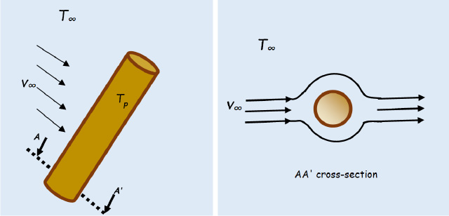
Figure 4.2. Flow outside a pipe: v∞. is in fact the flow velocity far from the pipe. For a color version of this figure, see www.iste.co.uk/benallou/energy3.zip
Analysis of this type of flow in fluid mechanics shows that the pressure distribution in the fluid is not uniform, particularly in the vicinity of the pipe (Knudsen and Katz, 1958; Schlichting, 1987; Landau and Lifshitz, 1989). We thus define a stagnation region, that is, the area in the vicinity of the pipe where the pressure increases as the velocity tends towards zero.
Thus, given that flow conditions to a large extent determine heat transfer by convection, the heat transfer coefficients in the vicinity of the pipe will not be the same as those obtained further away from the pipe. Two situations will therefore need to be distinguished for the calculation of h: in the stagnation region and beyond this region.
4.3. Correlations for the stagnation region
It is in this region that heat transfer between the fluid and the tube wall occurs. Consequently, we will be interested in calculating the convection heat transfer coefficient between the tube and the fluid sweeping it in the stagnation region.
The Nusselt number in this zone is a function of Re and Pr. It is provided in different forms by different authors (Jakob, 1949; Eckert and Drake, 1959; Knudsen and Katz, 1958; Jakob and Hawkins, 1957; Zukauskas, 1972). We will retain the following form, which is valid for both liquids and gases (Jakob, 1949; Zukauskas, 1972):

where:  , where D is the external diameter of the pipe.
The fluid’s physical properties are expressed at average temperature,  , with T and Tw the average temperatures of the fluid and of the pipe wall, respectively.
Constants C and m are given in Table 4.1 for different intervals of the Reynolds number.
Table 4.1. Values of constants C and M for flow through a cylindrical pipe
| Re interval | 0.4–4 | 4–40 | 40–4,000 | 4 x 10³–4 x 10⁴ | 4 x 10⁴–4 x 10⁵ |
| C | 0.989 | 0.911 | 0.683 | 0.193 | 0.027 |
| M | 0.330 | 0.385 | 0.466 | 0.618 | 0.805 |
4.4. Correlations beyond the stagnation zone
In certain applications, we are interested in heat transfer occurring beyond the stagnation area. For situations such as this, the Whitaker relation is used:

All of the physical properties are expressed at the temperature of the fluid and μw is expressed at the temperature of the wall.
4.5. Forced convection outside non-cylindrical pipes
Certain practical applications use pipes with square, elliptical or hexagonal shapes. This type of pipe is encountered above all in air-conditioning systems and in electronic-card cooling systems. For the different geometries considered in the literature, we will retain the following relations, which are valid for gases (Jakob, 1949; Zukauskas, 1972).
4.5.1. Pipes with a square cross-section area
4.5.1.1. Straight square
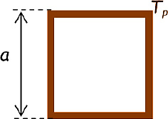
The Nusselt number is given by:  , where:
 being the side of the square.
The fluid’s physical properties are expressed at average temperature,  , T∞ and Tw the average temperatures of the fluid and of the pipe wall, respectively.
This relation is applicable for: 5 × 10³ ≤ Re ≤ 105.
4.5.1.2. 45°-inclined square

The Nusselt number is given by:  , where:

δ is the diagonal of the square
The fluid’s physical properties are expressed at average temperature  , with T∞ and Tw the average temperatures of the fluid and of the pipe wall, respectively.
This relation is applicable for: 5 × 10³ ≤ Re ≤ 105.
4.5.2. Pipes presenting an elliptical cross-section area
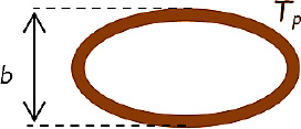
The Nusselt number is given by:  , where:

b is the minor axis of the ellipse, measured from the outside
The fluid’s physical properties are expressed at average temperature,  , with T∞ and Tw the average temperatures of the fluid and of the pipe wall, respectively.
This relation is applicable for: 5 × 10³ ≤ Re ≤ 105.
4.5.3. Pipes presenting a hexagonal cross-section area
4.5.3.1. Hexagonal pipe with two horizontal sides

Figure 4.6. Hexagonal cross-section with two horizontal sides
The Nusselt number is given by:  , where:

δ is the outer height of the hexagon
The fluid’s physical properties are expressed at average temperature,  , with T∞ and Tw the average temperatures of the fluid and of the pipe wall, respectively.
This relation is applicable for: 5 103 ≤ Re ≤ 105.
4.5.3.2. Hexagonal pipe with two vertical sides
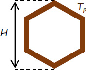
For this configuration, the correlation to be used in order to calculate the Nusselt number depends on the interval in which the Reynolds number is situated:
- – For
 ;
; - – For
 ;
;
where:

H is the hexagon’s highest length, measured from the outside
The fluid’s physical properties are expressed at average temperature,  , with T∞ and Tw the average temperatures of the fluid and of the pipe wall, respectively.
4.6. Forced convection above a horizontal plate
4.6.1. Plate at constant temperature
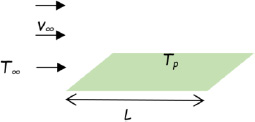
In practice, we often encounter situations where a fluid flows along a horizontal plate with constant temperature Tp. In such situations, the transfer coefficient depends on the flow regime and the distance, x, from the inlet. The local Nusselt number is given, as a function of x, by:
- – In laminar state: Re < 5 × 10⁵:

- – In turbulent state: 5 × 10⁵ ≤ Re ≤ 107 and 0.6 ≤ Pr ≤ 60:

The average Nusselt number for the entire plate is given by:
- – laminar state: Re < 5 × 10⁵:

- – turbulent state: 5 × 10⁵ ≤ Re ≤ 107 and 0.6 ≤ Pr ≤ 60:

where:

L is the total length of the plate in the flow direction.
The fluid’s physical properties are expressed at average temperature,  , with T∞ and Tw the average temperatures of the fluid and of the plate, respectively.
When the flow can be considered laminar across the entire plate, we then use the first relation to calculate Nu, and therefore h.
In general, where the value of L is sufficiently high and turbulent flow prevails across the entire plate, with a fairly limited laminar area, we use the turbulent flow relation to calculate the average heat transfer coefficient for the entire plate.
Yet, in reality, flow is laminar across part of the plane (at the start) and turbulent across the rest. We then use the following correlation, which gives an average Nusselt number, to be used for the entire plate:

where:  and
and  .
.
4.6.2. Plate with constant flow density

Figure 4.9. Plate with constant flow density. For a color version of this figure, see www.iste.co.uk/benallou/energy3.zip
Certain configurations, encountered fairly frequently in practice, correspond to the flow of a fluid of temperature T∞ across a horizontal plate, which generates a constant thermal flux density, φ.
In such situations, the transfer coefficient depends on the flow regime. The local Nusselt number, at distance x from the inlet, is given by:
- – In laminar state: Re < 5 × 10⁵:

- – In turbulent state: 5 × 10⁵ ≤ Re ≤ 107 and 0.6 ≤ Pr ≤ 60:

where:

and x is the distance considered, starting from the plate entry
The fluid’s physical properties are expressed at average temperature,  , with T∞ and Tw the average temperatures of the fluid and of the plate wall, respectively.
For the two flow regimes, the heat flux exchanged between the plate and the fluid is given by: ϕ = φ Ax, where Ax is the transfer area on the x-axis: Ax = bx.
The average temperature of the plate on the x-axis is then calculated based on the convective flux equation, namely:

Hence:  .
.
4.7. Forced convection around non-cylindrical objects
One of the most commonly-used heat treatments of solids consists of cooling objects by immersing them into a stream of cold fluid. That is why in this subsection, we will be focusing on scenarios where objects of various shapes (spheres, flat plates, etc.) are immersed in fluids that are in forced motion. In such cases, heat transfer occurs in the laminar boundary layer, even in cases where the flow beyond the stagnation area is very clearly turbulent (Schlichting, 1987). The calculation of transferred fluxes, and therefore convection heat transfer coefficients, is thus of significant importance in such situations. The following sub-sections present the relevant correlations.
4.7.1. Forced convection around a plane parallel to the flow

Figure 4.10. Forced convection around a plane parallel to the flow
In this case, heat transfer between fluid and plate takes place on either side of the latter. The summaries presented concerning the Nusselt number, by Eckert and Drake (1959) and Jakob (1949 and 1957), enable us to estimate the Nusselt number in the stagnation area:

where: 
δ is the length of plane in the flow direction
All of the physical properties are expressed at the temperature of the film,  , with θp the temperature of the wall and θ∞ the fluid approach temperature, i.e. far from the plate.

4.7.2. Forced convection around a sphere
The case of spheres immersed in a fluid in motion is often encountered in practice for situations involving the tempering or cooling of spherical pellets. Generally, a sphere of diameter δ is subject to a fluid flow at v∞, with approach temperature θ∞.
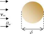
The Nusselt number, in the stagnation area, is a function of Re and Pr, given by (Jakob and Hawkins, 1957; Knudsen and Katz, 1958; Eckert and Drake, 1959):

where:

δ is the diameter of the sphere
All of the physical properties are expressed at the temperature of the film,  , with θw the temperature of the wall and θ∞ the fluid approach temperature, i.e. far from the sphere.

4.8. Convective transfers between falling films and pipes
This is the case for liquids streaming in a thin layer, by gravity inside or outside the wall of a vertical or horizontal tube. In such situations, the liquid flows as a film along the periphery of the tube, under the influence of gravity. We then speak of gravitational flows, or falling films.
The hydraulic diameter is defined by:  .
.
But, in this case:
- – A is the cross-section area of the streaming film;
- – P is the wetted perimeter involved in the exchange: P = πD;
- – D = De if the flow occurs outside the tube;
- – D = Di if the flow occurs inside the tube.
The Reynolds number related to the hydraulic diameter is then obtained as follows:

Yet, the term Avp represents the mass flow rate, which we will note W:
W = Avρ. Hence:  .
.
By writing  , we have:
  .
.
4.8.1. Vertical tubes
The following correlations were developed on the basis of works conducted by Bays and McAdams (1937). They lead to correct orders of magnitude for all liquid types:
- – For a barely viscous liquid (water): ReH > 2,100:

- – For a viscous liquid (oils): ReH ≤ 2,100:

Be sure to note that in the previous correlations:
- – L is the length of the tube;
- – The term
 is dimensionless;
 - – The relations themselves are not dimensionless; h has the same unit as
 ;
; - – The physical properties of the liquid are taken at the average temperature of the film, defined by:

with:
θwm is the average temperature of the wall
θm is the average temperature of the fluid
4.8.2. Horizontal tubes
For horizontal tubes, the correlation specific to barely-viscous liquids remains applicable, but that relating to viscous liquids needs to be changed. Thus, we will use:
- – For a barely viscous liquid (water): ReH > 2,100:

- – For a viscous liquid (oils): ReH ≤ 2,100:

4.9. Forced convection in coiled pipes
Coils are very commonly used to cool liquids as they exit their production units. Generally, the fluid to be cooled flows inside a coil, which itself is placed in a tank having a large volume. Using this helical shape for the tube (coil) aims at having a large transfer area in contact with the tank liquid.

Figure 4.12. Coil tank. For a color version of this figure, see www.iste.co.uk/benallou/energy3.zip
Consider a pipe of internal diameter di and external diameter do. This pipe is rolled into a coil of a helical form of diameter Dcoil. The coil is placed in a tank of diameter Dtank, stirred with a turbine of diameter δ.
For the flux calculations, the following three heat exchange situations need to be differentiated between:
- – Transfer between the fluid circulating inside the coil and its wall, hi;
- – Transfer between the external wall of the coil and the cooling fluid, he;
- – Transfer between the cooling fluid and the tank wall.
4.9.1. Convection heat transfer coefficient inside the coil
The heat transfer coefficients between the inner wall of a coil and the fluid circulating therein, hi, are estimated based on the same correlations presented in Chapter 2 for straight pipes, but with some modifications, to which great attention needs to be paid. These modifications involve the diameter of the coil, Dcoil (see Figure 4.12) and the inner diameter of the tube, di. The calculations are operated in two steps:
- – Step 1: we calculate the Reynolds number:
 ;
; - – Step 2:
- - If Re > 104, then:

- - If 2,300 ≤ Re ≤ 104, then:

- - If Re < 2,300, then:

- - If Re > 104, then:
Be sure to note that in the previous correlations:
- –
 ;
; - – The physical properties are taken at
 and T2 being the fluid temperatures at the coil inlet and at the coil outlet, respectively.
4.9.2. Convection heat transfer coefficient with the outer wall of the coil
To estimate the heat transfer coefficients he between the outer wall of a coil and the fluid in which it bathes, we use the following correlations, which take into account the turbine type used to stir the tank.
4.9.2.1. Blade-disk turbine
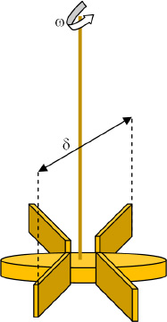
Figure 4.13. Turbine with blade disk
For a turbine of diameter δ (see Figure 4.13), the following correlation (Oldshue and Gretton, 1954) is used when a coil of external diameter, de, is placed in a tank of inner diameter, Dtank:

where:
Nue is the Nusselt number attached to the outer diameter of the coil. It is given by:

Rem is the Reynolds number attached to the mixer defined by:  :
:
δ is the diameter of the turbine
ω is the rotational velocity of the turbine (in revolutions per second)
μ is the viscosity of the fluid in the tank
ρ is the density of the fluid in the tank
This relation is applicable for 400 ≤ Rem ≤ 2 × 10⁵
4.9.2.2. Straight-blade turbine

Figure 4.14. Straight-blade turbine
For this type of turbine (Figure 4.14), the following correlation (Chilton, Drew and Jebens, 1944) is used for a coil tube of external diameter, de, placed in a tank of inner diameter, Dtank:

where: Nue is the Nusselt number attached to the outer diameter of the coil. It is given by:  .
.
The definitions of the remaining parameters are the same as in the previous case.
This relation is applicable for 300 ≤ Rem ≤ 4 × 10⁵.
4.9.3. Convection heat transfer coefficient between the fluid and the tank
As for the previous scenarios, the heat transfer coefficient, hTank, between the cooling (or heating) fluid contained in the tank and the inner wall of this tank depend on the type of turbine used for mixing (Chilton, Drew and Jebens, 1944; Brooks and Su, 1959; Uhl, 1959)
4.9.3.1. Blade-disk turbine
For this type of turbine (see Figure 4.13), the following correlation (Brooks and Su, 1959) is used for a tank of inner diameter Dtank:

where:
Nutank is the Nusselt number attached to the inner diameter of the tank, Dtank. It is given by:  , where htank is the convection heat transfer coefficient between the fluid of the tank and its wall.
Rem is the Reynolds number attached to the mixer defined by:  :
:
δ is the diameter of the turbine
ω is the rotational velocity of the turbine (in revolutions per second)
μ is the viscosity of the fluid in the tank
ρ is the density of the fluid in the tank
This relation is applicable for 400 ≤ Rem ≤ 3 × 10⁵.
4.9.3.2. Straight-blade turbine
For straight-blade turbines, such as that represented in Figure 4.14, it will be necessary to use the Uhl correlation (1959) for a tank of inner diameter Dtank and a turbine of diameter δ.

where:

htank is the convection heat transfer coefficient between the inner wall of the tank and the fluid it contains.
δ is the diameter of the turbine
ω is the rotational velocity of the turbine (in revolutions per second)
μ is the viscosity of the fluid in the tank
ρ is the density of the fluid in the tank
This relation is applicable for 300 ≤ Rem ≤ 3 × 10⁵.