6
Convection in Nanofluids, Liquid Metals and Molten Salts
6.1. Introduction
In recent years, there has been growing interest in a specific class of heat-transfer fluids: nanofluids. These are generally liquids which carry, in suspension, solid particles of nanometric size, consisting of metals or metal oxides. What benefit do they offer? A significant improvement in the thermal characteristics of the fluid thus formed. This improvement justified their use, among others, in refrigeration machines (Bouton, 2012), in solar collectors and in circuit-boards cooling systems (Minkowycz et al., 2013).
Moreover, the term “liquid metal” is used for metals that are in liquid state under ordinary pressure. They are often used in industry to ensure heat transfers at very high temperatures, but under ordinary pressures. Indeed, at such pressures, very few materials remain liquid when temperatures exceed 200°C. Yet, several practical applications involve heat transfers at temperatures that can even exceed this order of magnitude. This is the case in metallurgy, where heat treatment of materials requires high-temperature tempering. This is also the case for nuclear reactors, where energy produced in the core needs to be conveyed towards primary heat exchangers (Sandeep, 2012). Thus, for fast-neutron reactors (which operate at low pressure and at high temperature), the cooling fluid used can be liquid sodium. It can also be made up of certain alloys, which have lower melting points than those of the materials of which they are composed, such as the eutectic formed by lead and bismuth (Cheng and Nam-il-Tak, 2006). In this field, lithium is also used to cool fusion reactor blankets.
Another class of heat-transfer fluid that has been of particular interest over the last few years is that of molten salts. The latter are used in concentrating solar power stations, where the energy collected in cylindro-parabolic collectors or in towers must be transferred, at ordinary pressures, to storage tanks supplying steam generators: see Volume 7 (Solar Thermal Engineering) and exercise 3.36 at the end of Chapter 7.
6.2. Transfers in nanofluids
One way to improve the performance of heat-transfer fluids is to introduce metal oxide particles (Fe3O4, Al2O3, CuO, magnetite, SiO2, TiO2, etc.) in order to significantly increase the heat conductivity (Minkowycz et al., 2013). The particles need to be very small in size, however, so as not to hamper the flow, and to avoid creating erosion on the walls of the conveyor tubes. Their size needs to be of the order of thousandths of a micron. We then speak of nanoparticles and the resulting suspensions are nanofluids (Das et al., 2007). Table 6.4 gives orders of magnitude for the average diameters of several nanoparticles.
| Nanoparticles | Average diameter |
| Silver | 10 nm |
| Copper | 25 nm |
| Synthetic diamond | 6 nm |
| Aluminum oxide | 25 nm |
| Zinc oxide | 20 nm |
| Carbon nanotubes | 1-2 nm |
A nanofluid is thus a liquid (water, ethylene glycol, glycolated water, oil, etc.) in which we mix a low percentage of nanosized particles.
Incorporating nanoparticles into a given fluid modifies its physical properties (Chen et al., 2009). This is also easy to see when we compare the thermal conductivities of metals or metal oxides with those of liquids (see Table 6.2).
Table 6.2. Comparison of thermal conductivities
| Material | Water | Glycolated water (50%) | Engine oil | Al2O3 | Cu | Al |
| (Wm-1°K-1) | 0.60 | 0.41 | 0.14 | 40 | 401 | 237 |
This change is taken advantage of in specific applications, notably in heat transfer (Maiga et al., 2005). As such, nanofluids are used in processes to cool electronic power circuits, in new domestic refrigerators, in plate heat exchangers (Minkowycz et al., 2013), etc. This is thanks to improved thermal conductivity and dispersion of the nanoparticles in the fluid, which lead to greater convection heat transfer coefficients (Philip et al., 2006). Other significant advantages can be drawn from the use of nanofluids, noting in particular that the application of a magnetic field can considerably improve heat transfer in a given direction (Shima and Philip, 2011). It is thus possible to “dose”, in a variable manner, the amount of energy to be transferred in a given direction. This is called smart cooling. Within this context, the explorations conducted by Azizian et al. showed that the application of an external magnetic field to the convection transfer in a nanofluid consisting of water and magnetite, in laminar flow, leads to a transfer that is up to three times greater (Azizian et al., 2016).
Moreover, one of the most promising applications at present is the use of nanofluids as coolants in solar collectors (Otanicar et al., 2011; Phelan et al., 2013). In this case, the nanoparticles make it possible not only to improve the transfer (Khullar et al., 2014; Taylor et al., 2015) thanks to the best convective coefficients, but also to increase the capture of incident radiation, thanks to the absorptions and reflections of radiation by the nanoparticles. This leads to significant increase in solar collector efficiency (Taylor et al., 2011; Khullar et al., 2017).
6.2.1. Physical data
Suspending nanoparticles in a fluid inevitably changes its physical properties. The properties of the mixture obtained (nanofluid) can be estimated based on those of its components (liquid + solid).
Appendix 1 , at the end of this volume, groups together the different correlations aimed at calculating the physical properties of nanofluids. The following subsections give the correlations for calculating the heat conductivity, viscosity, density and heat capacity of nanofluids.
6.2.1.1. Heat conductivity
Given that particulates contribute to heat transfer, the heat conductivity of a given nanofluid will depend on the amount of nanoparticles used. This amount tends to be characterized by the nanoparticle volume fraction, defined by:

where:
VP is the volume of the nanoparticles
Vnf is the volume of the nanofluid
Several models are proposed in the literature for calculating nanofluid heat conductivity (see Appendix 1). We will retain the Udawattha and Narayana model, which seems to best correspond to the experimentation results:

where:


ω is the volume fraction of the nanoparticles
VP is the volume of the nanoparticles
Vnf is the volume of the nanofluid
ρf is the density of the fluid (in kg·m−3)
Cpf is the sensible heat of the fluid (in J·kg−1·K−1)
μf is the viscosity of the fluid (in kg·m-1·s-1)
kB is the Boltzmann constant
T is the temperature (in °K)
dP is the average diameter of the particles
δ is the thickness of the boundary layer of the nanofluid (around 1 nm)
r is the average radius of the particles, 
λ is the heat conductivity (in W·m−1·K−1), with the following system of indices:
nf for the nanofluid
f for the fluid
P for the particle
6.2.1.2. Viscosity
Several models are proposed in the literature for calculating nanofluid viscosity (see Appendix 1). We will retain the Udawattha and Narayana model, which seems to best correspond to the experimentation results:

where:


ω is the volume fraction of the nanoparticles, 
ρP is the density of the nanoparticles (in kg·m−3)
kB is the Boltzmann constant
T is the temperature (in °K)
dP is the average diameter of the nanoparticles
δ is the thickness of the boundary layer of the nanofluid (around 1 nm)
r is the average radius of the particles, 
e is the average distance between two nanoparticles, 
μ is the viscosity (in kg·m−1·s−1), with the following system of indices:
nf for the nanofluid
f for the fluid
6.2.1.3. Density and heat capacity
Nanofluid density has been expressed in simple terms, as a function of the nanoparticle volume fraction (Xuan and Roetzel, 2000):

where:
ω is the nanoparticle volume fraction, 
the indices nf, f and P refer to the nanofluid, the liquid considered and the nanoparticle, respectively.
The same type of expression was recommended for calculating the nanofluid sensible heat, based on the properties of the liquid and the particle (Pak and Cho, 1998):

6.2.2. Nanofluids circulating in tubes
6.2.2.1. In turbulent flow
As could be expected, the nanofluid Nusselt number increases with the volume fraction (Vajjha et al., 2010):

This relation has been established with nanoparticles of silica and copper oxide, with Reynolds numbers within the following range: 3,000 < Re < 16,000.
Works conducted recently (Jafarimighaddam and Aberoumand, 2016) have shown that this correlation enables representation of the experimental results with an average deviation less than or equal to 2% and a maximum deviation of the order of 10%.
A very good match between the experimental results and those of the following correlation was also reported (Xuan and Li, 2011):

where:

VP is the volume of the nanoparticles
Vnf is the volume of the nanofluid
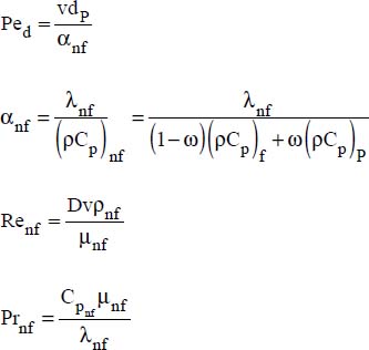
D is the pipe diameter
v is the average flow velocity
nf and P refer to the nanofluid and the nanoparticles, respectively.
6.2.2.2. In laminar state
Several authors have explored the determination of convective heat transfer coefficients (Wu et al., 2009; Chandrasekar et al., 2010).
For a constant flux at the wall, the following correlation is recommended:

where:

VP is the volume of the nanoparticles
Vnf is the volume of the nanofluid

D is the pipe diameter
v is the average flow velocity
nf refers to the nanofluid
200 < Re < 1,300 and 4.6 ≤ Pr ≤ 5.8
6.2.3. Nanofluids circulating within annular pipes
The study of heat transfer within annular pipes has recently been carried out, in laminar flow, for nanofluids consisting of copper particles suspended in an oil (Jafarimighaddam and Aberoumand, 2016). The following correlation is recommended. It enables us to find experimental results up to around 10%:

where:

VP is the volume of the nanoparticles
Vnf is the volume of the nanofluid
D1 is the external diameter of the inner tube and D2 the internal diameter of the outer tube:

where:
v is the average flow velocity
DH is the hydraulic diameter for calculations relating to the flow:

DH1 is the thermal hydraulic diameter, relative to the transfer with the inner tube:

DH2 is the thermal hydraulic diameter, relative to the transfer with the outer tube:
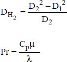
nf and f refer to the nanofluid and the fluid, respectively.
6.2.4. Superposition of natural and forced convections in nanofluids
An adaptation of the Proctor–Eubank correlation was proposed recently (Hekmatipour et al., 2017):

where:
μ is the fluid viscosity at bulk temperature
μw is the fluid viscosity at the wall temperature


6.3. Transfers in liquid metals
6.3.1. Physical data
Liquid metals and molten salts are practically the only fluids capable of performing heat-transfer tasks at very high temperatures. Liquid metals are appreciated for their high heat conductivities, which enable significant reductions in the overall thermal resistance. They also present fairly high boiling points, which prevent vaporization of the heat-transfer fluid. Appendix 1 (Database), at the end of this book, gives the physical properties of the liquid metals most commonly used in industry. Table 6.3 presents a sample of these.
Table 6.3. Fusion and boiling temperatures and heat conductivities of several metals
| Metal | TF (°C) | Tb (°C) | λ (W/m°C) at 20°C |
|---|---|---|---|
| Hg | -39 | 361 | 8 |
| Cs | 29 | 690 | 36 |
| K | 63 | 776 | 100 |
| Na | 98 | 914 | 140 |
| In | 157 | 1,450 | 82 |
| Li | 181 | 1,372 | 85 |
| Sn | 232 | 2,602 | 64 |
| Pb | 327 | 1,755 | 36 |
| Al | 660 | 2,057 | 240 |
| Cu | 1,083 | 2,300 | 394 |
In addition, liquid metals present the advantage of being non-volatile and enabling efficient pumping owing to their low electrical resistivity.
However, some liquid metals, such as sodium, are highly reactive with oxygen, which presents a significant fire hazard. Others, such as mercury, are highly toxic. As a result, their use should only be recommended under strict safety precautions and avoiding contact with air and water.
When the fluid in motion is a liquid metal, the relations presented in the preceding chapters, developed for fluids with a Prandtl number greater than 0.6, are no longer valid. Indeed, liquid metals have Prandtl numbers below 0.1. They constitute specific media in which the flow and therefore the heat transfer must be treated separately.
Moreover, in liquid metals in motion, conduction can be substantial enough to modify thermal fluxes transferred by convection (Seban, 1950; Hsu, 1964; Skupinski, Tortel and Vautrey, 1965; Kalish and Dwyer, 1967). These situations have been studied by several authors (Seban and Shimazaki, 1951; Lyon, 1952). In the following sections we will distinguish between the correlations obtained for circulation within tubes, between parallel planes and within annular spaces.
6.3.2. Liquid metals in forced convection within cylindrical pipes
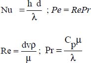
The literature distinguishes between two situations: constant wall flux and constant wall temperature:
- – constant wall temperature (Lyon, 1952): Nu = 7 + 0.025 0.8 0.8;
- – constant flux density at the wall (Seban and Shimazaki, 1951):

where:
6.3.3. Liquid metals in forced convection within an annular space
We need to differentiate between heat transfers with the inner tube and those with the outer tube.
6.3.3.1. Exchanges with the inner tube
- – Constant wall temperature:
 , where:

- – Constant flux density at the wall:
 ,
,
where:

6.3.3.2. Exchanges with the outer tube
- – Constant wall temperature:
 , where:

- – Constant flux density at the wall:
 ,
,
where:


6.3.4. Liquid metals flowing along a horizontal plane
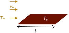
Figure 6.1. Flow on a plate. For a color version of this figure, see www.iste.co.uk/benallou/energy3.zip
The average Nusselt number is calculated from the relation:

where:  .
.
6.3.5. Liquid metals in forced convection between two parallel planes
Seban (1950) proposes the following correlation: Nu = 5.8 + 0.020 Pe0.8 , where:

6.3.6. Liquid metals subject to natural convection
For liquid metals flowing in natural convection along vertical plates, the relation to be used depends on the boundary condition:
- – for a uniform wall temperature:

where the “+” sign is used when the overall motion is in the direction of gravity; the “−” sign is used in the opposite case;
- – for a constant flux density at the wall: Nu = 0.73(Gr Pr2)0.20.
In the previous two correlations:
 .
.
6.4. Transfers in molten salts
6.4.1. Physical data
These are most often nitrates or fluorides of lithium, potassium or sodium, which have relatively high melting points (above 150°C), making them suitable for heat transfer at high temperatures. Very often, they are used in the form of mixtures, with the perspective of producing eutectics presenting wider areas of use in terms of temperature. Appendix 1 (Database) gives the most commonly used molten salts, along with their available physical properties (Sohal, Ebner, Sabaharwall and Sahrpe, 2010), whilst Table 6.4 presents the physical properties of a mixture, HTS (Heat Transfer Salt), marketed by DuPont de Nemours under the name HITEC, which is a mixture of KNO3 (53% mass), NaNO2 (40% mass) and NaNO3 (7% mass) (Roche, 1980). Furthermore, Table 6.7 presents the fields of application and the heat capacities for two common molten salts (HITEC and draw salt), compared to the same properties for liquid sodium and rock beds, which are traditionally used as storage for high temperatures (Lahmidi, 2005). It can be observed that for a given volume, the heat capacity of the molten salts is almost three times that of rock beds or liquid sodium.
Table 6.4. Physical properties of HTS
| T (°C) | 250 | 450 |
| (kg/m3) | 1,895 | 1,748 |
| Cp (kJ/kg°C) | 1.56 | 1.56 |
| (W/m°C) | 0.43 | 0.30 |
| (Ns/m2) | 4.57 × 10⁻³ | 1.53 × 10⁻³ |
| Pr | 15.3 | 7.3 |
Table 6.5. Draw salt and HTS compositions and fields of application
| Material | Weight composition (%) | Fields (°C) | Cp (J/kg°C) | ρ (kg/m3) | Cp (kWh/m3°C) |
| Draw salt | 50 NaN03/50 KNO3 | 220–540 | 1,558 | 1,733 | 0.75 |
| Draw salt | 60 NaN03/40 KN03 | 260–550 | 1,555 | 1,730 | 0.74 |
| HTS | 7 NaN03/53 KN03/40NaN02 | 142–540 | 1,543 | 1,680 | 0.72 |
| Liquid sodium | Na | 100–760 | 1,248 | 750 | 0.26 |
| Rock bed | - | - | 300 | 2,883 | 0.24 |
Molten salts are used for storing solar energy, where part of the energy received during the day is reserved in the form of latent heat, by melting a salt. This latent heat can then be recovered during the night by enabling the salt that is in molten state at the end of the day to solidify again during the night, releasing its latent heat.
Molten salts are also used as an energy-transfer (heat-transfer) fluid in concentrated solar power plants, where they transport energy between solar receivers (parabolic, cylindro-parabolic or towers) and steam generators (Pincemin, 2007).
Another important use of molten salts is to be found in fourth-generation nuclear reactors (Serp et al., 2014), where they are used as heat-transfer fluids (McPherson, 1985; Williams, 2015); notably “FLiNaK” (46.5% LiF, 11.5% NaF and 42% KF), and “FLiBe” (67% LiF, 33% BeF2).
Moreover, molten salts play three essential roles in thorium reactors, which seem to represent the future option of nuclear energy production (Clark, 2011; Halper, 2016). Indeed, they are used not only as coolants, but also as moderators of fission reactions and as an effective containment barrier.
The following sub-sections present the correlations that govern heat transfer in molten salts.
6.4.2. Molten salts under forced convection in laminar flow within cylindrical pipes
Several authors have studied heat transfer in molten salts in laminar flow. The correlations developed depend on Reynolds number.
6.4.2.1. Kays correlation
For Re ≤ 100 and smooth tubes (Kays and Leung, 1963): Nu = 4.364,
where:

d is the inner diameter of the pipe
v is the flow velocity of the molten salt within the pipe
The physical properties are expressed at the average temperature of the molten salt.
This correlation is valid for Re ≤ 100.
6.4.2.2. Skupinsky correlation
For 100 < Re ≤ 2,000, various studies have shown that the Nusselt number depends on the Péclet number alone (Dwyer, 1963; Skupinski, Tortel and Vautrey, 1965): Nu = 4.82 + 0.0185(RePr)0.827, where:

d is the inner diameter of the pipe
v is the flow velocity of the molten salt in the pipe
The physical properties are expressed at the average temperature of the molten salt.
This correlation is valid for 100 < Re ≤ 2,000.
6.4.3. Molten salts under forced convection in the transition zone within cylindrical pipes
For Reynolds numbers between 2,000 and 10,000, we can use the Wu correlation (Wu, Liu, Ma and Guo, 2009):

where:

d is the inner diameter of the pipe
v is the flow velocity of the molten salt in the pipe
The physical properties are expressed at the average temperature of the molten salt.
Prw is the Prandtl number, where the physical properties are expressed at the wall temperature.
This correlation is valid for 2,000 < Re ≤ 10,000.
6.4.4. Molten salts under forced convection in turbulent flow within cylindrical pipes
For Reynolds numbers greater than 10,000, we can use the correlation of Liu et al. (Liu, Wu, Ma, Ye and Guo, 2009): Nu = 0.024Re0.807Pr0.301, where:

d is the inner diameter of the pipe
v is the flow velocity of the molten salt in the pipe
The physical properties are expressed at the average temperature of the molten salt.
This correlation is valid for Re > 10,000.
6.5. Reading: Eugène Péclet and Lord Rayleigh
6.5.1. Eugène Péclet
Considered to be one of the greatest French physicists, Eugène Péclet was born on February 10, 1793 in Besançon, France. He was one of the first students to attend the prestigious École Normale, where he had great scientists as professors: Gay-Lussac, Ampere and Dulong. He graduated at the top of his class in 1812.
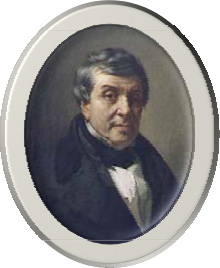
Figure 6.2. Eugène Péclet (1793–1857)
(source: Wikipedia1)
He was then appointed as Professor of physics at the Collège Royal, Marseille, in 1815. It was at this very college that he taught classes of what today would be called chemical engineering, which he came to call, over time, “classes in the application of chemistry to the arts”. As a result of these classes, which were greatly appreciated by industrialists, he established numerous contacts with the economic world and started to make a name for himself.
Thus, as well as being a brilliant scientist, Péclet was well known both to the industrial world and within the economic and commercial circles of the time.
Moreover, in addition to his many scientific activities, including teaching and research, Eugène Péclet was interested in the evolution of political life, government decisions and the actions of the opinion shapers of the time.
But his scientific rigor was often incompatible with the naturally “foggy” political practice. This led to his being removed from his position as Professor of physics at the Collège Royal in 1822, owing to his anti-government stance.
He then left Marseille for Paris, where in 1828 he founded, along with Jean-Baptiste Dumas and Théodore Olivier, the École Centrale des Arts et Manufactures, which is presently one of the leading engineering schools in France.
There, he taught general physics and industrial physics and held the role of Vice-Chairman of the Studies Council.
Above all, he is to be credited with the work he developed from 1828: his Traité élémentaire de physique (Elementary Treatise on Physics) and his Traité de la chaleur (Treatise on Heat).
6.5.2. Lord Rayleigh
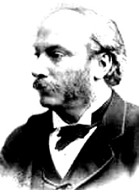
Figure 6.3. John William Strutt, Lord Rayleigh (1842–1919)
(source: Nobel Prize website2)
The discovery of convection as a heat transfer process can be attributed to Rumford in 1797, but true experimental and theoretical investigations only date back to the beginning of the twentieth century.
The decisive experiments were carried out in 1900 by Bénard, who studied the organization of convection in layers of viscous fluids heated by the base.
Bénard shows that when heating exceeds a certain critical value, conduction is no longer effective enough to evacuate all of the heat, and convection takes over: the bottom mass, which is hotter and more lightweight, rises. It then cools at the upper surface, becomes denser and falls back down. These mass movements create organized circulation of matter with upward hot currents and downward cold currants. Heat transfer occurs simply through these matter circulations.
In 1901, Boussinesq drafted a first theory of convection, completed by Lord Rayleigh in 1916.
The latter showed that the driving forces of convective motions are Archimedes forces, due to differences in density which are themselves due to temperature differences. In order for convection to be established, the driving forces must be greater than the viscous frictional forces. The condition is fulfilled if the ratio of driving forces (Archimedes forces) to viscous forces, a ratio known as the Rayleigh number, exceeds a certain value, called the critical Rayleigh number.