Goal Confirm the size and location of your PV array
Now that you’ve taken the first steps of estimating your energy needs and thinking about where your PV system might go, it’s time to take a closer look at both to determine the best location for the array and, ultimately, how big it needs to be. You’ll determine the size and output with PVWatts, the free online calculator provided by the National Renewable Energy Laboratory (NREL). PVWatts uses your home’s location and several other factors to estimate the amount of electricity you can expect to produce with a given system size. What it can’t do is visit your site, so it’s your job to measure your installation area, your roof slope, and your azimuth (not as bad as it sounds) and to consider additional factors, like shade, to come up with an accurate, realistic system size.

Area, slope, and azimuth are the measurements that describe the placement and position of your future array. They are the primary design factors that are specific to your site, and you will need them in order to use the PVWatts calculator.
Area: The usable square footage of roof space or ground area for installing the PV modules.
Slope: The angle, or pitch, of your roof. The slope determines the tilt of the modules.
Azimuth: The direction your roof or ground-mount array faces (south, southeast, west, etc.), measured in degrees.
With a rooftop system, all three of these factors are limited by what you already have or are planning to build. With a ground-mount system, you get to choose the slope (the module tilt angle) and azimuth, provided there is sufficient area in a suitable location with minimal shade.
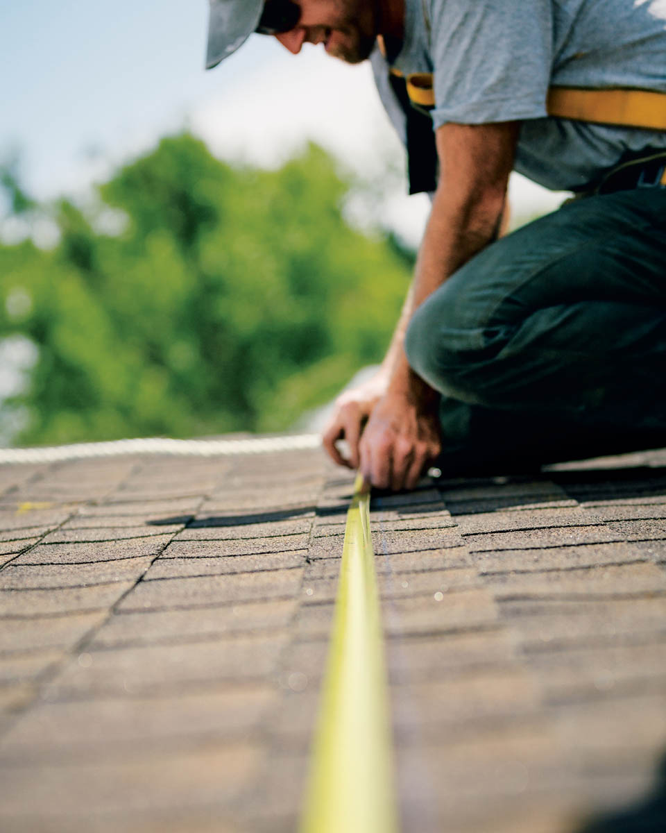
Accurate measurements are easiest with a helper and a 25-foot or longer tape measure. If you like, you can record your measurements on a simple map. The following steps apply to rooftop arrays. For ground-mount arrays, simply measure the available open space in the most likely installation area of your yard or property.
There are several methods for measuring roof slope. If you have a smartphone, see if it includes a level app (measures for levelness). This may be part of the compass app, which you’ll use to measure azimuth. Open the level app; set the phone, on edge, on the roof; and read the degree of angle given.
Another method is to use an inexpensive tool called an inclinometer. This works like an analog version of the phone app: set it on the roof and read the degree angle indicated by the arrow.
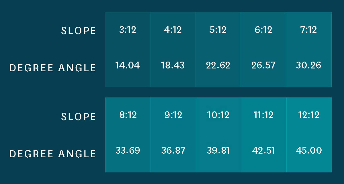
Then there’s the old-school method, which requires a little background. In builder’s parlance, the slope (or pitch) of a roof plane is expressed in a rise-run ratio. A 5-in-12 (or 5:12) roof pitch rises 5 inches for every 12 inches of horizontal run. The chart below shows that a 5:12 roof is angled at 22.6 degrees.
You can measure the rise and run with a framing square (carpenter’s square) and a small level, such as a torpedo level or 2-foot level (see the image below).
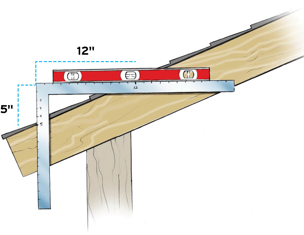
This roof has a 5-in-12 (22.6-degree) slope.
If you don’t have a square, use any level that’s at least 12 inches long (or attach a small level to a foot-long board) and a tape measure. Mark the level 12 inches from one end. Position that same end of the level against the roof and hold it level. Measure straight down from the 12-inch mark to find the rise.
Azimuth is the compass direction the PV array faces. For most rooftop arrays, this is also the direction the roof faces. An array facing due north has an azimuth of 0 degrees; due east is 90 degrees, due south is 180 degrees, and due west is 270 degrees. You can measure azimuth with a smartphone or an old-fashioned compass. Smartphones are easier because they calibrate themselves to your location so you don’t have to account for magnetic declination (the variation between true north and magnetic north). Compass apps also work on tablets, and you can download free versions for any compatible device.
To use a compass app, simply open the app and follow the instructions for calibration. When the app is ready, stand with your back to the roof where the array will go, and hold the phone flat in your hand and directly in front of you. The app gives you the precise angle the roof plane faces; this is the azimuth for your roof.
You can use an old-fashioned compass the same way. Just remember to account for magnetic declination for your location. If you don’t know that information off the top of your head, you can look it up with the online calculator provided by the National Oceanic and Atmospheric Administration (NOAA). Also, make sure there are no metal or other magnetic objects nearby, as this can throw off the compass needle. Don’t forget your metal watch or belt buckle!
For those of you planning a ground-mount array, it’s generally best if the array faces due south, an azimuth of 180 degrees.
PV arrays on sloped roofs typically mount to a “flush-mount” (parallel to the roof slope) racking system that is anchored into the roof framing. Arrays on houses with flat roofs use special supports that are held in place by weights (called ballast); the arrays are usually not fastened to the roof. Mounting structures are available with a variety of tilt angles, typically ranging from about 10 to 20 degrees and almost always less than 20 degrees. Modules at steeper angles are subject to higher wind loads and often must be mechanically anchored to the roof. Otherwise, the higher the tilt and/or wind loads, the more ballast is required. See Mounting Structures for Flat Roofs for more information.
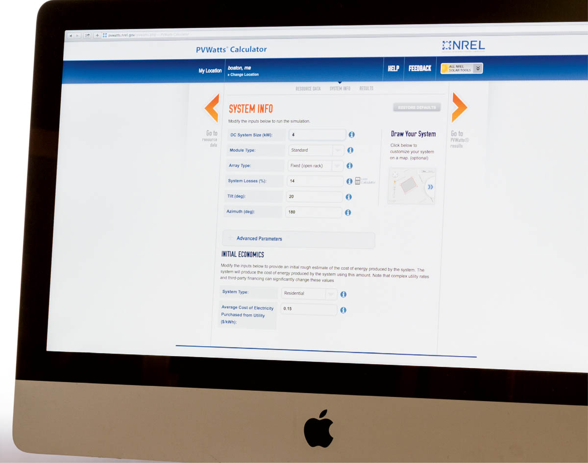
Just for fun, take a minute to go online to the PVWatts calculator (pvwatts.nrel.gov). Enter your city and state, then click “Go.” On the next page, click on the map location closest to your house, or stick with the default location selected for your city, then click on the big orange arrow labeled “Go to system info.” On the next page, click on the big orange arrow labeled “Go to PVWatts results.” Boom. The number in large type at the top is how much AC electricity you can produce per year at your location with a 4 kW (DC) system facing due south. The system size and other default inputs are already in the calculator.
Of course, your system may not face due south and it may not be 4 kW, but this 60-second exercise shows you how easy it is to start using PVWatts. No log-in or registration required, no cost, and no ads for treating toenail fungus. Now, that’s the government doing something right.
PVWatts is incredibly simple on the surface, but there’s much more you can do with it to improve accuracy. It’s designed for trial and error, so you can easily click back and forth between the pages, plug in different data, and immediately review the results. The “System Info” page is where you’ll enter your specific data.
The PVWatts “System Info” page includes six basic design parameters for sizing your PV system. We’ll briefly discuss each one here, and you can refer to PVWatts for more detail, as needed; just click on the “i” button to the right of each parameter. There’s also a button labeled “Advanced Parameters.” You can ignore this for now and rely on the system default inputs; chances are, you’ll never need to tweak these values.
System size is the rated output of DC power for the entire solar array (see STC Ratings). A system with an array of 20 PV modules rated at 250 watts each is a 5 kW system (20 × 250 watts = 5,000 watts). The default system size on PVWatts is 4 kW, but you can change this to any size you like. Don’t worry about entering a size at first; when all of your other parameters are in place, you can play around with different sizes and quickly check the results until you find a system size that yields your target power output.
Note that your target output is in AC and represents the amount of usable electricity produced annually by the system. The DC system size is not the same thing as the annual AC production. It’s easy to get confused here because, depending on where you live, the DC system size and the annual production may have similar numbers attached to them. For example, a 5 kW (5,000-watt) system may produce around 5,000 kilowatt-hours (kWh) of electricity annually. But for all intents and purposes you can consider this a coincidence. A 5 kW system is capable of producing 5,000 watts of DC electricity at a given moment under ideal conditions and peak sunlight. How much usable energy the same size system can provide your home each year is based on many factors, and that’s what PVWatts calculates for you. Using your location and your roof’s (or ground-mount’s) azimuth and tilt, it estimates how much sunlight your system will receive year-round and therefore how much electricity it is likely to produce.
This parameter lets you select one of three types of PV modules: standard or premium conventional crystalline-silicon (c-Si) modules or thin-film modules. Conventional c-Si modules are typical for home power systems, so you’ll likely either use standard modules (with an efficiency of about 15%) or you’ll pay more for premium modules (with efficiencies up to about 20%). If you know the exact modules you’ll be using, you can refer to the manufacturer’s data sheet to help choose standard versus premium. Otherwise, use the default type: standard. If you are using modules made from a-Si, CIGS, or CdTe solar cell material, then you will select “Thin-film” as your module type.
The array type is the module-mounting type: rooftop or ground-mount. If you’re installing a standard flush-mount rooftop system, select “Fixed (roof mount)” in the drop-down menu. If you’re doing a ground-mount system or a flat-roof system (where the modules are tilted up on a flat roof surface), select “Fixed (open rack),” unless you’re keen on using a tracking system (see What’s Tracking?, below). The fixed (open rack) option gives you a slight performance advantage due to the lower average temperature of a ground-mount (or flat-roof) array versus a flush-mount rooftop system. Most PV modules are slightly less productive in temperatures over 77°F (25°C), a temperature that’s easy for the solar cell material to hit on a rooftop. If you are using tracking, choose either “Single-axis” or “Dual-axis” for your array type.
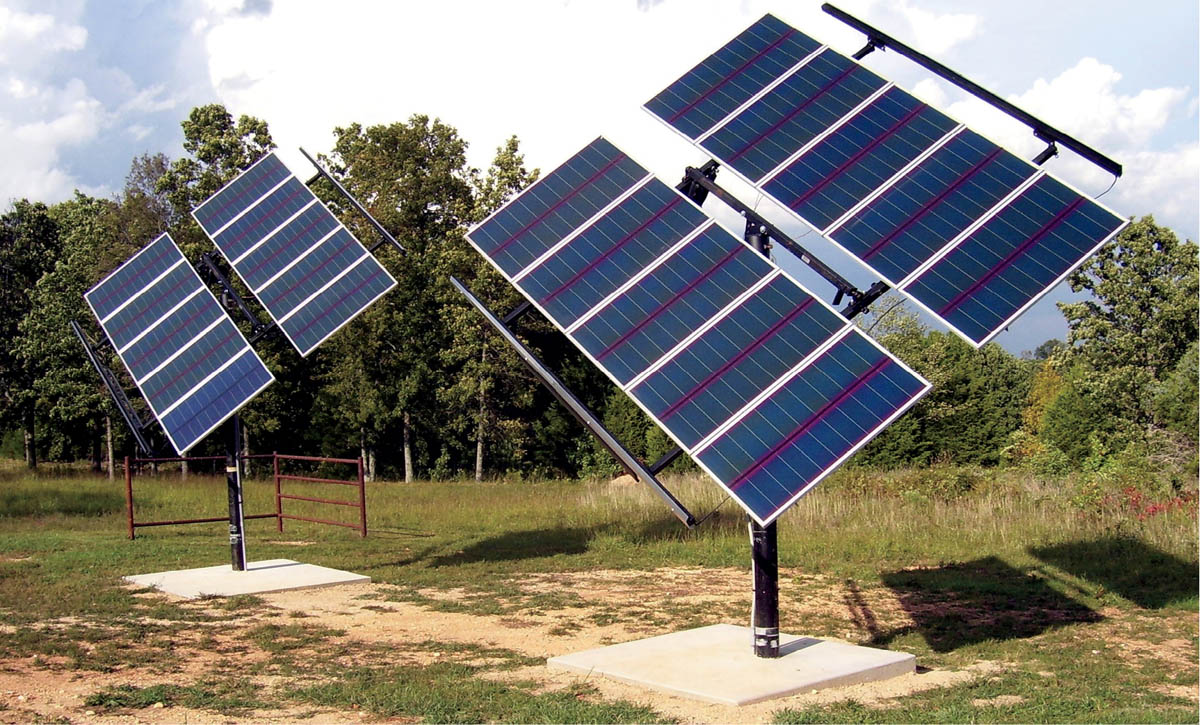
Tracking is usually an option for ground-mount systems only. It works by way of a motor or other device that automatically moves the PV array throughout the day to maximize solar irradiance (how much sun is captured by the modules). Single-axis tracking rotates the array from east to west, following the sun across the sky over the course of the day. Dual-axis tracking rotates and tilts the array so that it always faces the sun directly.
Residential systems with tracking typically involve single-pole mounts holding about 8 to 12 full-size modules. Larger systems require multiple mounts, each with its own tracking device. Given the added cost of tracking, most home power systems use a fixed ground-mount instead. Tracking also introduces moving parts and their maintenance needs. If you’re interested in tracking, it’s a good idea to consult a solar pro for design and installation advice.
Some fixed ground-mount array supports are adjustable and can be tilted manually to face the sun in different seasons. This offers some of the benefits of tracking without the added cost and maintenance issues. Alternatively, if you have the space, simply adding a few more modules to a fixed ground-mount array may offer the same output boost you would get with a tracking system but would do so more cheaply and, again, without moving parts and added maintenance.
In short, system losses are the total of all the little reductions in efficiency due to equipment inefficiencies and real-world operating conditions. The losses account for the difference between the maximum rated DC power of the array and the actual AC power that is fed to your house or the utility grid.
The default system loss value in PVWatts is 14%, giving you an overall system efficiency of 86% (100% – 14% = 86%). This means that if your array is rated for 5 kW of DC power, it would produce 4.3 kW of usable AC power (5,000 watts × 0.86 = 4,300 watts). However, we recommend a somewhat higher loss value of 18%; see the PV System Losses chart (below) for a breakdown. This is based on decades of experience with PV systems. Alternatively, you can learn about each loss category in PVWatts and enter your own values into the loss calculator to come up with a system losses percentage.
When converting DC ratings to AC output, we recommend an average loss value of 18%, based on the following ranges.
Soiling
2%–3%
(Dust/debris on modules, reducing current)
PV module mismatch
2%–3%
(Slight performance differences among modules can reduce overall efficiency)
Line losses
2%–3%
(Voltage drops as electricity travels through wires)
DC–AC inverter efficiency
2%–3%
(Losses in converting from DC to AC)
System availability
2%–3%
(Times when system is down due to equipment problems/maintenance)
Shading
2%–3%
(Production losses due to shading of modules)
PTC vs. STC rating
2%–3%
(Allowance for lower performance ratings; see here)
Total
14%–21%
(We recommend using 18%)
Tilt is the angle of your PV modules, measured in degrees: 0 degrees is horizontal; 90 degrees is vertical. For standard flush-mount installation on a sloped roof, enter your roof slope in degrees. For a ground-mount system, remember that you get to choose the tilt. A tilt equal to the latitude of your location is the standard compromise for year-round production. (A lower tilt yields higher production in summer; a steeper tilt is more productive in winter.) As an example, Denver, Colorado, is at 40 degrees latitude, so the standard tilt angle for ground-mount systems is 40 degrees; however, a tilt anywhere from 30 to 45 degrees will work fine in Colorado. You can look up the latitude of your location with an online latitude/longitude finder.
You can also plug in different tilt angles in PVWatts and compare the results. Note that the “Results” page gives you the array output for each month of the year, allowing you to see how a change in tilt affects output during different seasons. Also note that while the summer and winter values may change significantly as you vary the tilt, the total annual energy output may change by only a few percentage points. In other words, it usually balances out over the year.
Simply enter the degree value you calculated earlier. If you’re planning a ground-mount system and have some flexibility in positioning the array, you can play around with different azimuth values to confirm the ideal position for your location.
Once you’ve entered your basic parameters in the “System Info” page, click on the orange arrow labeled “Go to PVWatts results.” The number you get is the average annual kilowatt-hour production (again, in AC power) you can expect with a 4 kW system (the rated DC system size), unless you entered a different system size. This may be too low to meet your electricity needs (since the national average is about 11,000 kWh per year). If so, click the left arrow to go back to the “System Info” page, and enter a higher number for the “DC System Size.” Click the right arrow again for your results. Repeat as needed until you hit the magic number.
This is assuming your goal is to cover a typical year’s total electricity usage with PV power. You can certainly choose to cover more or less than that, but there are some important considerations with either route. If you go with a smaller system that produces less than your overall usage, the difference (for grid-tied systems) will be made up by utility power. This alone is not a problem; in fact, all grid-tied systems pull utility power on and off throughout the year and even throughout most days of the year. But keep in mind that the more utility power you use, the more you’ll be affected by rate increases over the years.
If you choose to install a bigger system that produces more power than you’re likely to use, be aware that utilities commonly put a cap on the amount of excess power residential PV systems can produce. For example, you may be limited to 120% of your annual usage. So if your annual household consumption is 10,000 kWh, you can’t install a system that’s capable of producing more than 12,000 kWh per year. (Utilities are forced to play nice with renewable energy producers, but they don’t have to be that nice.)
Here’s another consideration with large systems: Don’t assume that you’ll get full retail value for excess power that you sell back to the utility. In fact, it’s safer to assume that you’ll get much less. For example, you might pay the utility $0.10/kWh for grid power, but the utility might pay you only $0.05/kWh for your solar-generated electricity. And, because the pricing program is controlled by the utility, there’s no guarantee that you’ll get the same price (or any payback at all) indefinitely. Buyback rates, rules, and regulations, often generically referred to as net metering, are the subject of ongoing discussion among consumers, utilities, and regulatory commissions throughout the United States.
Designing anything for the outdoors comes with special challenges. In the case of PV systems, manufacturers have eliminated most of the usual concerns by making their modules and other exposed components tough and highly weather-resistant. So you don’t have to worry about things like rain, hail, and of course sun exposure. But snow, wind, and shade are site-specific factors that must be considered.
PV modules don’t produce electricity when they’re covered with snow. However, this is a minor concern in most snowy climates. For one thing, when it’s snowing it’s also very cloudy, so the modules wouldn’t produce much power even without the snow blanket. When the sun comes out, snow cover on solar arrays tends to melt relatively quickly because the modules heat up with solar radiation. If you want to speed up the process by clearing off some of the snow, use a wood-handled broom or mop that won’t scratch the module glass. The wood handle is for electrical safety. Do not use a shovel, which might damage the modules. Otherwise, just wait for the sun to take care of it.
If you have a ground-mount array, you don’t want ground snow or drifts covering or shading your modules. Simply install your array so that the lower edge is higher than the typical snow level. If you get an unusually heavy snow or drifting, you can shovel away the ground snow and wipe off the modules.
Rooftop systems require a couple of special considerations. The first is weight. Your roof and module mounting structure must be able to support the extra weight of snow loads (measured in pounds per square foot) in your area. You can learn about snow loads from the local building department, and they will surely be part of your design and permit approval.
The second consideration is avalanche. A PV array is essentially a big, smooth panel of glass. A heavy blanket of snow can lose its grip during melting, and everything slides down at once, dropping onto a deck, roof, walkway, or whatever else might be waiting innocently below. The standard way to minimize this risk is to keep the bottom edge of the array 2 feet or so above the bottom edge of the roof. Ask the local building department for specific recommendations. Also, you can install snow guards along the eave to break up the snow after it slides off the modules.
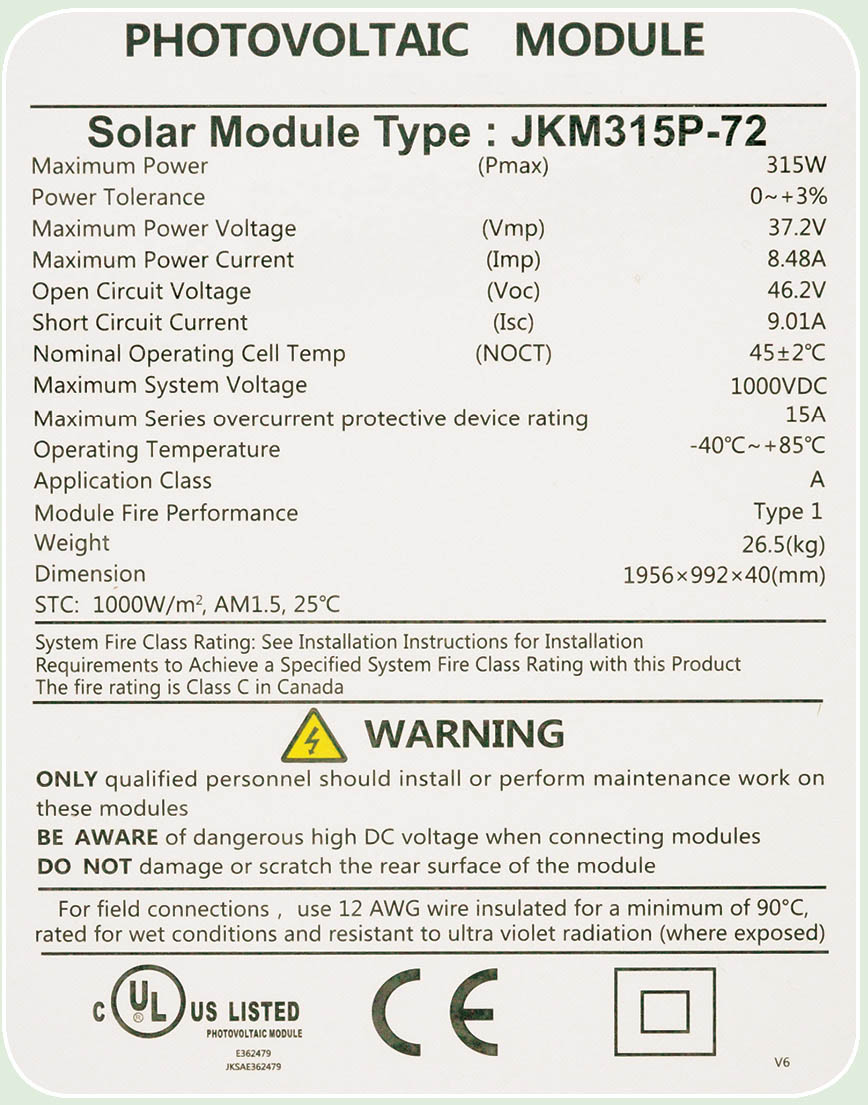
The rating of a PV module refers to its performance under standard test conditions (STC). This is essentially a car-mileage test for solar panels (as you might guess, actual mileage may vary). Modules carry a nameplate listing several STC criteria, such as voltage, current, and wattage. You will refer to some of these nameplate values when choosing your modules and other equipment during the design phase. The basic system is based on STC ratings, but you’ll also perform some calculations using “extreme” (non-STC) values.
For those who are interested in the scientific data behind STC, the testing conditions for measuring PV module performance include the following:
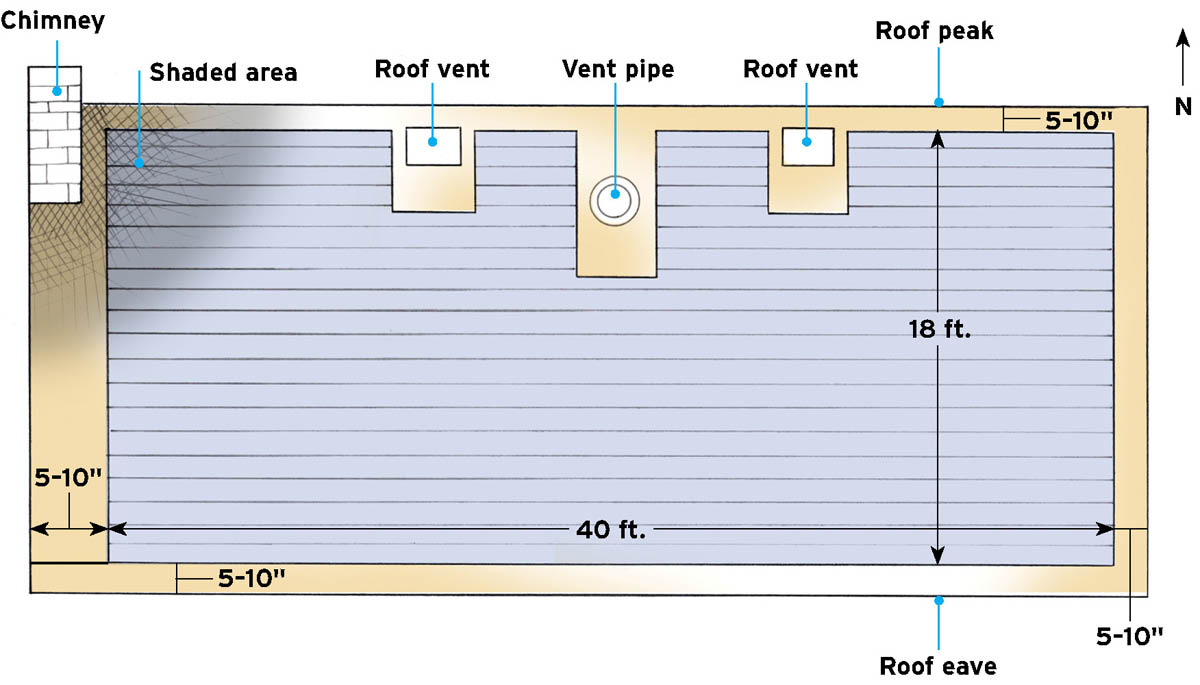
Wind is a standard design load that is established by the local building authority. Whether you’re installing a rooftop system or constructing a support system for a ground-mount, the building department will make sure your plan includes sufficient structural strength to resist wind forces at your location. Follow these specifications to the letter; you can imagine what might happen when a sail-like array isn’t properly secured. Wind is the reason rooftop modules are kept at least 5 to 10 inches from the roof peak and all edges, and why ground-mount structures are anchored in concrete or other equally secure foundations. Note: The local building department may require a letter with an engineer’s stamp verifying that your PV design (and roof) meets the local requirements for both wind and snow loads.
Shade has a compounded effect on PV module output. If a single leaf falls onto a module, shading even a single cell, the electrical output of that cell is reduced proportionately to the amount of shading. And because the cells are wired together in series, all of the other cells in that module have their outputs reduced equal to the reduction of the shaded cell, lowering the output of the entire module.
If the system has a traditional string-inverter setup, the problem gets worse. String inverters treat module strings as single units, not as individual modules. Therefore, shading of a single module results in a downgrade for the entire string, which might be up to half of your array. Newer string inverters have electronics that reduce shading losses. Additionally, most modules are now wired with bypass diodes, which bypass the shaded cell (or module), allowing the rest of the string to behave normally.
Microinverters treat modules individually, since each module (or module pair) has its own microinverter. This limits the effect of shading to a single module. Even so, if a tree limb or chimney casts a shadow across several modules, the production losses add up.
The bottom line is, shade is not good, so it’s important to install modules in areas with minimal shading.
So how do you know when an obstacle will shade your array/installation area? Apply the 21⁄2 times rule: The length of a shadow can be 21⁄2 times the height of the obstacle (when the sun is at its lowest position in the sky). For example, a 20-foot-tall tree can cast a shadow up to 50 feet long, depending on the sun’s position in the sky. (The longest shadows in the Northern Hemisphere occur on the winter solstice, between December 20 and 23.) With a rooftop array, you need to be concerned only with the relative height of the tree, that is, the portion of the tree that extends above the roof level. With a ground-mount array, you need to consider the full height of the tree, minus the array’s distance above the ground. Also, with ground-mount arrays with multiple rows, you must space the rows so that they don’t shade one another.
The easiest way to assess shading potential at your site is with your eyes: check the installation area at different times throughout the day (and throughout the seasons, if possible) to see whether, when, and where shadows appear. Combining visual inspection and the 21⁄2 times rule is sufficient for most situations. For a more detailed assessment, some solar pros use a Solar Pathfinder, a simple but expensive instrument that is set up on-site and provides data on year-round sun exposure and potential shading. If you choose this route, it’s probably best to have an expert do it for you. The Solar Pathfinder unit costs about $300, and while some installers swear by them, others find them too finicky or difficult to use and not worth the trouble.
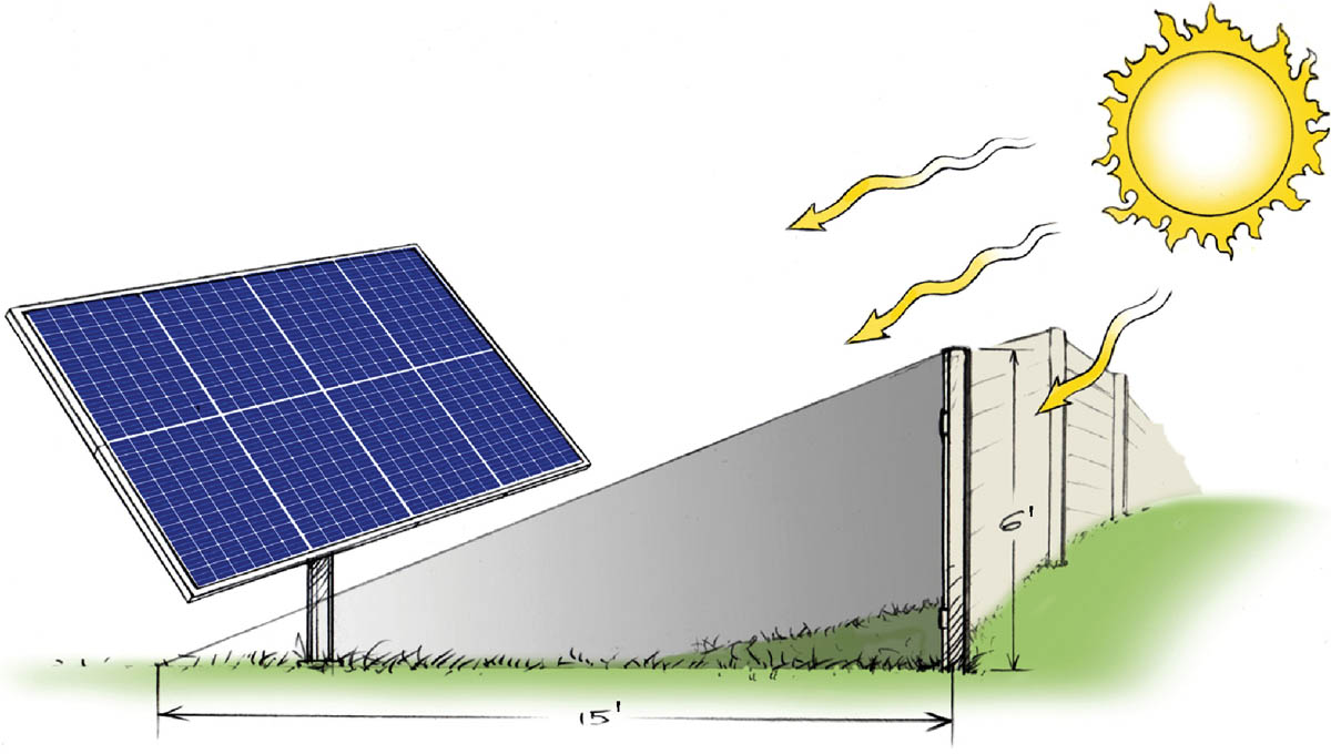
Obstacles can cast a shadow 21⁄2 times their height when the sun is low in the sky. The higher the sun’s angle, the shorter the shadow.