Chapter 12. Artificial Intelligence: BatBot
Have you ever wondered if robots will take over the world? If so, you’re not alone. Hollywood and the media have done an excellent job of trying to convince us of an impending robot revolution.
To complete such a mission, robots would need to be smart enough to work together and develop a plan to take over the world. To accomplish this, however, they would need some human-enabled intelligence, also known as artificial intelligence. Fortunately, we are a long way off from enabling robots to work together at such a large (and certainly scary!) scale, but artificial intelligence is still very useful for all sorts of applications, and that is why we’re going to spend this chapter playing with it!

Figure 12-1. BatBot
In this chapter, I’m going to talk about artificial intelligence (AI) and three categories of artificially intelligent robots (remote-controlled, semi-autonomous, and fully autonomous). And then you’re going to build BatBot, as shown in Figure 12-1, a semi-autonomous robot.
Artificial Intelligence: The Basics
As humans, our ability to make decisions and act on them is what has propelled us to the top of the intellectual food chain. Our abilities to reason, rationalize, and remember give us the leg up on other species who can’t do it quite as well.
When we talk about artificial intelligence, all we really mean is using algorithms to simulate decision making. An artificially intelligent being (i.e., a robot) relies entirely on these algorithms to know what to do in certain situations. In most circumstances, robots don’t learn like humans do; they have to be taught absolutely everything.
Machine learning is the one exception to the AI rule. To be clear, however, even machine learning has its limitations. Machine learning is simply a series of increasingly complex algorithms (like Haar Cascades in neural networks) that can be used to “teach” a robot how to discern different pieces of its environment, to which it can apply other decision-making models.
I like to group robots into one of three categories, ranging from least to most artificially intelligent: remote-controlled, semi-autonomous, and autonomous.
Remote-Controlled Robots
Remote-controlled (RC) robots have no artificial intelligence. They are completely controlled by a human, and thus their decision making is non-existent. Humans make every decision for the robot.
Examples of remote-controlled robots include RC cars, simple circuits, and computer numerical control (CNC) machines. There is a direct correlation between what the human wants to do and what the robot does, for better or for worse (if a human makes a mistake, the robot makes a mistake, too!).
Semi-Autonomous Robots
Semi-autonomous robots have some artificial intelligence. They get most of their instructions from a human, but also make some of their own decisions based on factors in their environment about which the human either doesn’t know or doesn’t care to know.
Examples of semi-autonomous robots include the Mars rovers, da Vinci surgical robots, and Parrot AR drones. Humans give the robots the important instructions (“go explore that area”), but the robot has enough sensors and artificial intelligence to make its own decisions within those parameters (like avoiding obstacles or dampening subtle movements due to shaking or wind turbulence).
Autonomous Robots
An autonomous robot is controlled entirely by artificial intelligence. After receiving some initial instructions from a human, it makes all of its own decisions. Many people like to argue that there are no fully autonomous robots in existence yet, as most robots still require a significant amount of human intervention. However, subsystems of semi-autonomous robots can be fully autonomous.
Examples of semi-autonomous robots with autonomous components include the Google self-driving car, the Nest thermostat, and commercial airplanes (think autopilot). After being given a mission (“drive to X” or “keep my house at Y degrees”), they use their sensors and artificial intelligence to figure out how to complete their task.
BatBot
To really play with artificial intelligence, we’re going to teach BatBot how to find its way out of a paper bag. It’s a silly challenge, yes, but the lessons that result from this exercise are the foundations for any artificially intelligent robot.
BatBot is a semi-autonomous robot: we’ll remotely control it (so that we can put it in the bag), and then tell it to find its own way out using its ultrasonic (sonar) sensor. As hinted by its name, BatBot will use sonar to navigate its way out of the paper bag. To add a bit of fun, we will use a Playstation DualShock Controller to navigate it remotely via Bluetooth, and use XBee radios to keep the robot separate from the computer.
Bill of Materials
| Count | Part | Source | Estimated price |
|---|---|---|---|
1 |
MaxBotics Ultrasonic Rangefinder LV-EZ2 |
AF 980; SF SEN-08503 |
$25 |
1 |
Generic high-torque standard servo |
SF ROB-11965; AF 155 |
$12 |
1 |
100 ohm resistor |
Electronics retailers |
$10 for a variety pack |
1 |
100 uF capacitor |
Electronics retailers |
$1.50 |
Headers |
Online Electronics retailer |
$2 for a variety pack |
|
Jumper wires |
MS MKSEEED3; SF PRT-11026; AF 758 |
$2 for a variety pack |
|
1 |
XBee wireless kit |
SF KIT-13197 |
$100 |
Glue gun and glue sticks |
Online retailer |
$10 |
| Count | Item | Source | Estimated price |
|---|---|---|---|
1 |
Arduino Uno |
MS MKSP99; AF 50; SF DEV-11021 |
$25 |
1 |
BOE Bot Robotics Shield Kit for Arduino Uno |
MS MKPX20; SF ROB-11494 |
$130 |
5 |
AA batteries |
Online retailer |
$5 |
1 |
PS3 or PS4 DualShock controller |
Online retailer |
$45 |
| Item | Source | Estimated price |
|---|---|---|
Bat wings, cut out of felt or similar |
Local craft store |
Varies |
A ridiculously large paper bag, like a lawn paper bag for disposing of autumn leaves, with most of the sides cut down |
Your local hardware store |
$3 for a pack of five |
Decorative accessories (e.g., googly eyes, a feather boa, etc.) |
Local craft store |
Varies |
Some Notes About the Materials
The focus of this chapter is making robots smarter, with more of an emphasis on software than on hardware. As such, while I assume you have the materials listed, you also have completely free reign on the materials you choose to use for your robot. For example, instead of using an Arduino Uno, you can use a SainSmart Uno R3. Instead of a BOE Bot, you can use a SimpleBot (described in Chapter 1) or a SumoBot Jr.
You may also skip the XBee wireless kit and simply use a very, very long USB cable (the longest you can find!), and replace the large paper bag with three sturdy walls made of non-signal-absorbent material (Styrofoam is especially bad for this project). If you choose to use a different type of ultrasonic sensor, refer to the Johnny-Five-sanctioned list of sonar sensors. Simply put, feel free to get creative—the really interesting bits are when you get to the software portion!
Many of the smaller components like the resistor and the capacitor can be acquired with some of the other components: for example, the BOE Bot Robotics Kit includes such components, as do many Arduino starter kits.
There will be some soldering required for this project. If you don’t feel comfortable with your soldering skills, you should practice a bit or ask for assistance. The soldering isn’t particularly complex, but it does require a bit of finesse.
Assembly
Let’s start building!
-
First, assemble your chassis according to the manufacturer’s instructions. We won’t be making any special modifications to the chassis except adding to it, so building it should be fairly straightforward.
-
Solder some headers to the sensor (Figure 12-2) , so that you can easily fiddle with your connections. The most important connections for this project are GND (ground), +5 (voltage in), and AN (analog output signal).

Figure 12-2. Ultrasonic sensor with headers before soldering
-
Attach your sonar to a servo horn using hot glue (Figure 12-3): it’s easy to take apart if you mess up, but holds really well. As an added bonus, it won’t damage any of your components, and your bot shouldn’t be heating up hot enough at any point to risk the glue melting again.

Figure 12-3. Ultrasonic sensor with servo horn, attached with hot glue
-
Attach your standard servo to the front of your bot using hot glue, as shown in Figure 12-4. Be sure to attach the servo in such a way as to ensure that the sonar will rotate left to right, pointing ahead of the robot.

Figure 12-4. Servo attached to batbot
-
Wire up the sensor array according to Figures 12-5 and 12-6, which will also require the 100 ohm resistor and the 100 uF capacitor.
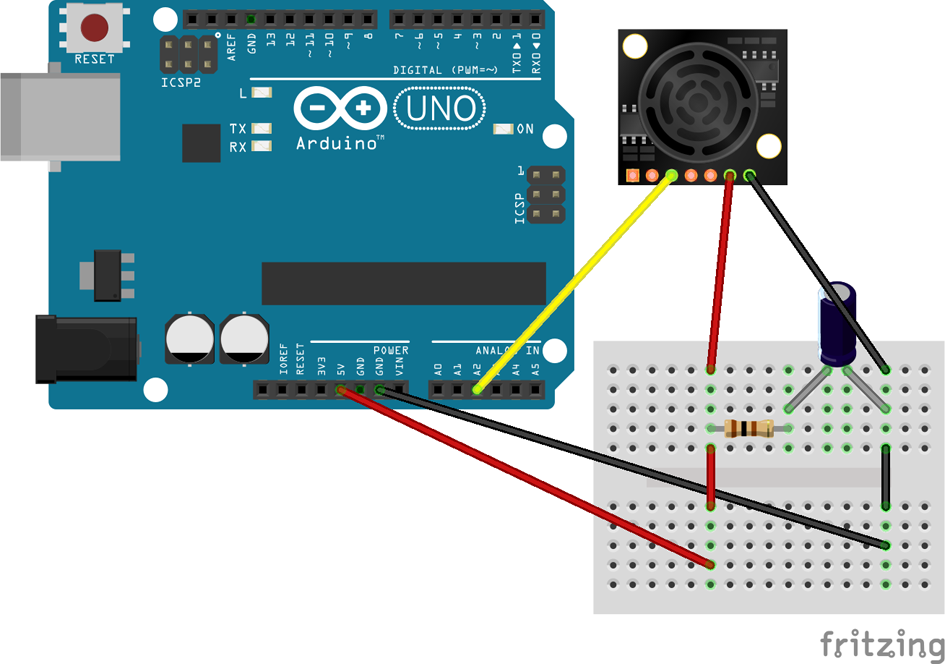
Figure 12-5. Fritzing diagram of sonar sensor array

Figure 12-6. Schematic diagram of sonar sensor array
-
Once you’ve attached the sonar, now is a great time to add some finishing touches. Add a pair of wings, flame stickers, or whatever suits your fancy. Just make sure it doesn’t get in the way of the wheels or the sonar; you want to make sure the robot can still make readings and move freely so it can finish its task!
Now that you have all of the major bits in place, let’s get to the meat of this project: artificial intelligence!
Step 1: Remote Control
Before you can get to the really awesome fun part of making BatBot find its way out of a paper bag, you’re going to need to figure out how to talk to BatBot:
-
Ensure you have the latest stable version of Node.js and npm installed on your computer. If you still need help with installing Node.js and need a primer on how to use npm to install modules, see the appendix.
-
Get the code for BatBot, located in the batbot/ folder in the Make: JavaScript Robots repository on GitHub.
-
On your local copy of the code, find your way into the batbot/ directory and run
npm installto install all of the packages listed in the package.json file. I’ll introduce each module as you need them. The first and most important one isjohnny-five, which allows you to send commands to the Arduino and thus move the servos and read from the sensor.
Moving the Robot
Now that you have a robot and your software environment is set up, the next major task is to get BatBot moving around under your direction. From there, you can move on to encouraging BatBot to drive itself.
Let’s take a closer look at the chassis.
Notice that the BOE Bot comes with two continuous servos, one for each wheel. Each wheel moves independently, which will allow the robot to move in any direction: forward, backward, left, and right.
A continuous servo moves continuously in a single direction (i.e., clockwise), like a motor. Where it differs from a standard motor, however, is that we can programmatically tell it to move in the opposite direction (i.e., counterclockwise). (To make a standard motor switch directions, on the other hand, you would have to physically change the polarity of its inputs.)
As you can see in Figure 12-7, the two servos are pointed in opposite directions. This means that in order for the robot to move in a straight line, the servos are going to have to turn in opposite directions (i.e., one will turn clockwise while the other turns counterclockwise). Keep in mind, though, that both wheels will still turn in the same direction.

Figure 12-7. Simplified diagram of robot movement
Similarly, if both servos turn in the same direction, the robot will turn! For this project, when the robot turns, you want it to turn in place. To do this, one wheel needs to turn backward at the same rate that the other wheel turns forward.
By implementing each servo separately, you have the logic shown in Table 12-4 for moving the robot.
| Direction of Movement | Left Servo Direction | Right Servo Direction |
|---|---|---|
Forward |
Forward (ccw) |
Forward (cw) |
Backward |
Backward (cw) |
Backward (ccw) |
Left |
Backward (cw) |
Forward (cw) |
Right |
Forward (ccw) |
Backward (ccw) |
Remember, all of the source code for the examples in this book can be found on GitHub. You’ll need to follow these steps:
-
Go ahead and create a new file in the batbot/ directory called moveBot.js. Initialize
johnny-fiveand begin our program like so:varfive=require("johnny-five");varboard=newfive.Board();board.on("ready",function(){// do stuff}); -
Next, implement each continuous servo using the
johnny-fiveservo API. Add the following code after requiring thejohnny-fivemodule, but before initializing the board:varleftServo=five.Servo.Continuous(10);varrightServo=five.Servo.Continuous(11);The pin number corresponds to the connection of each servo to the BOE Bot shield and thus to the Arduino. You must also specify that these servos are continuous servos, as opposed to standard servos.
-
To make it easier to control each servo, write a
movefunction, following the logic for robot movement described in Table 12-4:varmoveSpeed=0.1;functionmove(rightFwd,leftFwd){if(rightFwd){rightServo.cw(moveSpeed);}else{rightServo.ccw(moveSpeed);}if(leftFwd){leftServo.ccw(moveSpeed);}else{leftServo.cw(moveSpeed);}} -
For a given movement, you want the right wheel to move forward or backward, and the same for the left wheel. Your code uses booleans to dictate the direction of each wheel. With this, you can abstract each movement out even further with easier-to-remember functions:
functionturnLeft(){move(false,true);}functionturnRight(){move(true,false);}functiongoStraight(){move(true,true);}functiongoBack(){move(false,false);} -
Don’t forget to include a
stop()function as well:functionstop(){lServo.stop();rServo.stop();} -
You can play with the servos and move functions in the
johnny-fiveREPL by passing them into thejohnny-fiveREPL object:this.repl.inject({left:leftServo,right:rightServo,turnLeft:turnLeft});and then in the
johnny-fiveREPL:leftServo.cw
();leftServo.stop();turnLeft();
Controlling the Robot
Now that you have the wheels hooked up with johnny-five, let’s add the PS3 DualShock Controller. The dualshock-controller module will allow you to map different keys on the controller to specific events.
-
Add the
dualshock-controllermodule into the mix. Depending on your model of controller, you may need to changedualShock3todualShock4:varfive=require("johnny-five");vardualshock=require("dualshock-controller");ds=dualshock({config:'dualShock3'}); -
You can make it so that when you press the triangle button, the robot moves forward in a straight line, via the
goStraightfunction. Remember, this goes inside theboard.on("ready", ...)block:ds.on("triangle:press",function(){goStraight();});ds.on("triangle:release",function(){stop();}); -
Map as many buttons to whatever functions suit your fancy. Remember to stop the robot when you let go of a button! Otherwise the robot will continue forever and ever. By only moving on keypresses, you will have much more control of your robot.
With your DualShock Controller mapped to your servos, you should now be able to remotely control your robot!
Try it out—how does it feel?
Pointing and Reading from the Sonar
Now let’s hook up the sonar and its associated standard servo into the mix:
-
Because the sonar is an analog sensor, you need to wire it up to one of the analog pins on the Arduino:
varsonar=newfive.Sonar("A2"); -
Throw the sonar into the REPL, and start playing around with the readings, using
sonar.cmorsonar.inches. What happens when you point it at different materials? Do you notice a pattern in readings? Is there a minimum reading or a maximum reading? You can read more about thejohnny-fivesonar API on GitHub. -
You should notice that the sensor emits higher values for objects that are farther away. You may also notice that the object doesn’t necessarily need to be directly in front of the sonar to get a reading. This is due to the MaxBotix sensor’s beam characteristics.
For maximum control of the sonar sensor, it is attached to a standard servo. Unlike a continuous servo, which moves continuously, a standard servo moves to a specified angle measurement. The benefit of a standard servo in this application is that we can specify exactly where we want the sonar to point. We can see the johnny-five servo API on GitHub.
-
Initialize the sonar servo:
varsonarServo=newfive.Servo({pin:12,range:[10,170]});The
rangeparameter allows you to set a minimum and maximum angle for the sonar servo; this way, instead of having to constantly remember which angle is “left,” “center,” and “right,” you can simply saysonarServo.max(),sonarServo.center(), andsonarServo.min(), respectively.Depending on how you’ve mounted your servo to the robot,
sonarServo.max()andsonarServo.min()may mean right and left, respectively. This is perfectly fine; just be sure to make the adjustments to your code as necessary. -
To finish, map the servo movement and sonar readings to your DualShock Controller:
varangle=15,sonarStep=10;ds.on("r2:press",function(){console.log(sonar.cm);});ds.on("l2:press",function(){angle=(range[0]+range[1])/2;sonarServo.center();});ds.on("dPadLeft:press",function(){angle=angle<range[0]?range[0]:angle+sonarStep;sonarServo.to(angle);});ds.on("dpadRight:press",function(){angle=angle>range[1]?range[1]:angle-sonarStep;sonarServo.to(angle);});ds.on("dpadUp:press",function(){angle=range[1];sonarServo.max();});ds.on("dpadDown:press",function(){angle=range[0];sonarServo.min();});The r2 button press gives you sonar measurements, while the l2 button centers the servo. Then you’re using the direction pad to incrementally move the servo in steps of
sonarStep(and stopping at the minimum/maximum we set when we initialized it). You’re also using the direction pad to move entirely to the maximum and minimum ranges. You’re keeping track of the angle yourself to ensure you have the maximum amount of control.
Be careful when driving your bot around—make sure it’s on a flat surface, preferably on the floor. If you must drive it around on a table, make sure you have someone standing guard who can catch the bot if (when!) something goes wrong.
Drive it around the room—how does it handle? Would you like to do anything differently? Feel free to play around, tweaking numbers. Make it your own!
Step 2: Autonomy
The next step on your journey to artificial intelligence is to take your remote-controlled robot and make it smart! To achieve this goal, you need to fully understand the problem at hand, break it down into smaller problems, “teach” the robot to handle those smaller problems, and walk away once the greater problem has been solved. The steps you follow now will be useful for any artificial intelligence problem, beyond helping BatBot find its way out of a paper bag.
Start by clearly identifying the problem: you have a paper bag, situated on the floor. The opening is pointed out, so that the robot can drive into the bag. Once in the paper bag, its task is to navigate its way back out, using only the ultrasonic sensor and its driving mechanism.
The robot goes into the bag, pointing at the back wall. How should it get out?
If you’re having trouble seeing the world from the robot’s perspective, pretend that you are the robot. Imagine that you are blindfolded, or the room is very dark. The only information you have is that there is or isn’t a wall in front of you. On top of that, you can only turn 90° or move forward/backward. Now how do you get out of the room?
Your first thought may be to turn around by 180° and walk out.
While that’s a perfectly valid answer, you’re using a priori data (facts you knew before you walked into the room, like knowing that the room has three sides and you walked in through the open end). The robot doesn’t have that information.
The goal of this exercise shouldn’t be to answer this specific question, but instead to answer a general set of problems. This problem of the paper bag is essentially three walls, but it can be easily extended to solving a simple maze.
A common maze-solving algorithm is the wall follower algorithm, also known as the lefthand rule or the righthand rule. The general idea is that by following a wall with either your left or right hand along the wall, you will eventually find the end of the puzzle.
But going back to this problem’s limitations, you only know if there’s a wall in front of your eyes, not if you’re parallel to a wall (though you can play around with that idea in a future iteration!).
It’s important to note that the robot has no idea about where it is relative to anything else. It only knows the information it has at a particular moment, with no sense of memory.
For this specific application, then, there is an even simpler algorithm:
-
Check if there is a wall to the left of me, in front of me, and to the right of me.
-
If one of the directions has no wall, turn 90° or drive toward the opening; go back to step #1.
-
If there isn’t, turn 90° to the right and go back to step 1.
By using this pattern, you don’t need to have any information about the room, and you can use the sensors you have available to make decisions.
Implementing the Algorithm
Now that we’ve settled on an algorithm, let’s write it up in the code:
-
First, check to see if there is a “wall” to the right of the robot. Point the standard servo to the right with
sonarServo.max()and take a sonar measurement withsonar.cm.Next, turn the servo to the front (
sonarServo.center()), take a measurement, and finally to the left (sonarServo.min()) with a measurement as well:sonarServo.max();varrightVal=sonar.cm;sonarServo.center();varfrontVal=sonar.cm;sonarServo.min();varleftVal=sonar.cm; -
Bind the start (and stop!) of the scanning algorithm to buttons on your DualShock Controller, to make it easy to put your robot in (and out of) autonomous mode:
ds.on('select:press',function(){console.log('IN AUTO MODE');varloop=setInterval(function(){ds.on('r1:press',function(){clearInterval(loop);});// your algorithm goes here});});
Try it out and see what happens. What kind of values are you getting?
It’s not quite working, is it? It turns out that, with this piece of code, the sonar readings are happening too fast for the servo to keep up.
JavaScript, as a language, is unique in that it is asynchronous by nature. When it sends a command, it doesn’t wait for the command to complete before sending the next one. In the case of the servo/sonar combination, you’re sending the commands in succession, almost instantaneously, and you’re moving on to the next command before its predecessor has had a chance to complete.
What you want to do, instead, is give each command as much time as it needs to complete before beginning the next command. As a result, for this specific application, you’re going to have to force the algorithm to be synchronous.
Fortunately, there’s a library called temporal that will allow you to specify when each servo movement/sonar measurement takes place:
-
Add the
temporalpackage to your code:varfive=require("johnny-five");vardualshock=require("dualshock-controller");vartemporal=require("temporal"); -
Using
temporal, create a queue that moves the servo and takes a measurement every 1,500 milliseconds (i.e., 1.5 seconds):varscans=[];temporal.queue([{delay:0,task:function(){sonarServo.max();scans.push({dir:"left",val:sonar.cm});}},{delay:1500,task:function(){sonarServo.center();scans.push({dir:"center",val:sonar.cm});}},{delay:1500,task:function(){sonarServo.min();scans.push({dir:"right",val:sonar.cm});}}]);You may have noticed that now you’re pushing our sonar measurements into an array. By using the
array-extendedmodule, you have some very useful utilities for manipulating arrays and extracting useful data. -
Add the
array-extendedmodule to the code. -
Take the array of three directional measurements and find the one that is mostly likely to be the open wall (given that higher sonar measurements indicate the wall is farther away):
varmaxVal=array.max(scans,"val"); -
Now use that information to implement the rest of the algorithm:
WALL_THRESHOLD=15;// cmvardirection=maxVal.val>WALL_THRESHOLD?maxVal.dir:"right";if(direction==="center"){goStraight(1000);}elseif(direction==="left"){turnLeft(700);}else{turnRight(700);}The
WALL_THRESHOLDis the value at which anything below it implies that there is a wall present; anything above it is too far away and can be considered an opening. -
To improve accuracy, take multiple scans in each direction and average them out using the
array-extendedmodule:varscanSpot=function(cb){varsServoReadings=[];varread=setInterval(function(){sServoReadings.push(sonar.cm);if(sServoReadings.length===10){clearInterval(read);cb(null,array.avg(sServoReadings));}},100);};Here’s what’s going on: when you call
scanSpot(), you’re taking a servo reading every 100 milliseconds (i.e., one-tenth of a second), and logging that in an array. After 10 sonar measurements, you usearray-extendedto find the average, and return that value via the callback. The callback ensures that you wait for this function to finish before you move on to the next step in the algorithm.
Put together, Example 12-1 shows the complete algorithm.
Example 12-1. Finished algorithm
varscans=[];temporal.queue([{delay:0,task:function(){sonarServo.max();scanSpot(function(err,val){scans.push({dir:"left",val:val});});}},{delay:1500,task:function(){sonarServo.center();scanSpot(function(err,val){scans.push({dir:"center",val:val});});}},{delay:1500,task:function(){sonarServo.min();scanSpot(function(err,val){scans.push({dir:"right",val:val});});}},{delay:1500,task:function(){WALL_THRESHOLD=15;minVal=array.min(scans,"val").val;varmaxVal=array.max(scans,"val");vardirection=maxVal.val>WALL_THRESHOLD?maxVal.dir:"right";if(direction==="center"){goStraight(1000);}elseif(direction==="left"){turnLeft(700);}else{turnRight(700);}}}]);
You’re going to want to repeat all of this indefinitely, or until you tell it to stop. Take a look at the sonarscan.js file for the complete version.
Time to try it out! Drive your robot into the paper bag and turn on autonomous mode! How does it do? Feel free to make adjustments until your robot achieves success.
Troubleshooting
- My XBees aren’t communicating—what’s going on?
-
Make sure your have them properly configured. See GitHub for more information.
- Why does the robot sometimes not listen to my DualShock Controller commands?
-
First, make sure that you’re intentionally stopping/starting the robot in your code. If you’re absolutely positive that the code is good, it might be your XBee or Bluetooth connection. XBees are known to have some packet loss, but generally if you send another command it will set itself right again. Try replacing the XBees with a USB cable. If everything works perfectly, there’s either something wrong with the XBee connection or your hardware setup. If that’s not it, check your code again.
- My robot isn’t seeing the opening of the paper bag
-
Check to make sure the top of the bag isn’t dipping into the conical beam of the ultrasonic sensor.
What’s Next?
Congratulations! Your little BatBot can now, on its own, find its way out of a paper bag, as shown in Figure 12-8!

Figure 12-8. BatBot’s movin’ on out!
While artificial intelligence requires quite a bit of concentrated thinking, it also really takes your robots to the next level. Want to go deeper? Try some of these exercises to go further in your artificial intelligence mastery:
-
Instead of making the robot turn in place, make it turn in an arc
-
Make the robot find its way out of a longer paper bag
-
Make the robot solve a maze
-
Implement the wall follower algorithm
-
Find and implement more interesting/complex algorithms to solve this puzzle
-
Make a robot that avoids obstacles