Over the past few years, continuous innovation and the need to adapt to the constraints of conventional networking has made software defined networking (SDN) pretty popular. Let's discuss what is so special about SDN that legacy technology is not able to deliver.
The current design of network infrastructure does not support dynamic scalability, central control and management, end-to-end visibility and dynamic traffic load distribution. It is an approach that physically separates the network's control plane from the data plane. This allows network administrators to program directly without having to worry about the commodity hardware specifications.
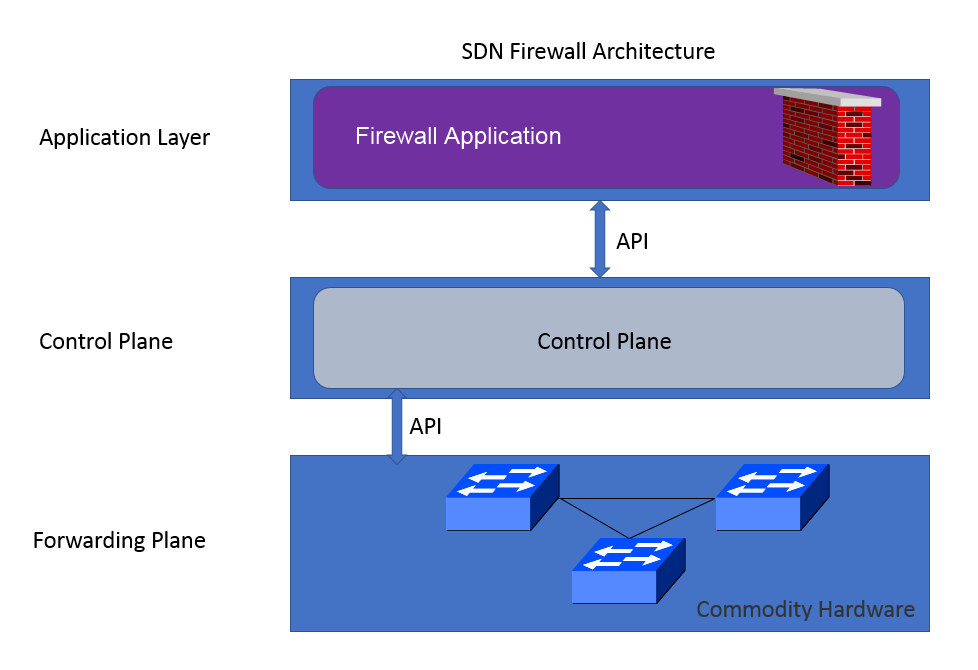
The following diagram shows SDN architecture. The SDN architecture can be divided into three layers: Application Layer, Control Plane, and Forwarding Plane.

In this section, we will discuss how we can use SDN functionality for firewalls. A firewall is a device that filters incoming and outgoing traffic in the network that has passed through network devices based on firewall rules. A traditional firewall is placed between a public and private network. The rule configuration is defined by the network administrator and, with every new rule, firewalls have to be configured. Hardware firewalls are expensive and vendor locked-in, which means that only vendors can modify the behavior of the firewall. As discussed, software defined networking is a new approach to networking. SDN offers the flexibility to convert commodity-based OpenFlow supported hardware into firewalls, which is software managed.
Control Plane is used for management tasks and has a global view of network topology. All decisions regarding forwarding the packets are made by the Control Plane. The controller uses an OpenFlow protocol to communicate with commodity switches and it also has the capability to change the flow of entries directly into a TCAM table of switches. Similar to the firewall rule, the flow entry is used for matching purposes and has actions associated with the flow.
A typical flow table looks like the following diagram. Header fields are fields that should be matched to IP packets and the actions would be defined by the administrator.

Overall, this approach creates a distributed firewall architecture and rules are pushed across all the devices or specified groups of device. In this diagram, you can see three layers: Firewall Application, Control Plane, and Forwarding Plane.
The following table demonstrates a firewall flow and rule:
