Chapter 5
More on the Ebony Spline
Woodworking is not a static affair. If it were, we would never enjoy new innovations or designs. Methods of work should not be immovable objects, but rather considered only the best way we know how at this time. In my last book, I presented the reader with a method for making Greene & Greene ebony splines. While that original technique is still valid, I have developed a new method, which requires more initial outlay in resources, but the process then becomes more streamlined and the results more pleasing.
I cannot claim ownership of the new idea though. That goes to my friend Graham Jackson, who at one time worked for me. Although a brilliant proposal, it had some bugs. The jigs evolved over the period of three or four years with my students and visitors to the shop pitching in with some cerebral heavy lifting along the way. I will not say this is the only, or the best way, to produce the ebony spline detail. I will say, though, that this is the best way I know how at this time.
A. Template Plate
B. Bottom Plate
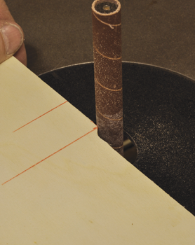
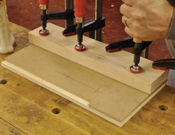
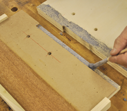
1. Place a pencil mark 4½" down from one end of the plate. Run the part past the set up until the cut reaches the pencil line.
2. Sand to shape with a small spindle sander set up.
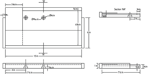
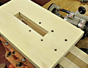
The Template Plate
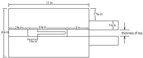
To get started, review the drawings for the ebony spline-shaping jig. As you can see there are basically two parts to the jig. The bottom plate positions the stock and registers the template plate. The template plate clamps down from the top to hold the blank immovable, while also serving as a contour template.
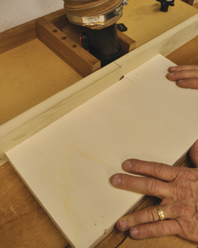
First, take two pieces of ½" plywood that are about 8" by 15½" and laminate them together to achieve the needed 1-inch thickness of the template plate. Next square up one corner of the glued up ply and cut it, as well as another piece of ½" ply (to be used later for the bottom plate) to 7 ½" x 15". Continue by setting up a router table with a ½" straight cutting bit and a fence that is offset by exactly 3⁄16", the out-feed side being farthest out.
Adjust the out-feed side of the fence so it is flush with the top-dead-center of the router bit, the same as you would adjust the out-feed table of a jointer. If set up correctly, the stock should rest evenly and flat on both the in-feed and out-feed sides of the fence as it runs past the router bit. If this is not the case, re-adjust the top-dead-center alignment to the out-feed side of the fence. Place a pencil mark 4½" down from one end of the plate. Run the part past the set up until the cut reaches the pencil line. To finish off the template’s shape, a ¼" radius is needed to smooth out the sharp corner left by the router bit cut. Use a Berol R-75 radius guide or other device to trace the radius, then sand to shape with a small spindle sander set up.
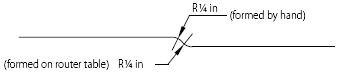
C. Template Plate Radiuses
A ¼" radius is needed to smooth out the sharp corner left by the router bit cut.
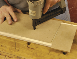
3. Attach MDF pieces to the bottom plate.
4. Laminate a 1⁄16" thick piece to the bottom plate.
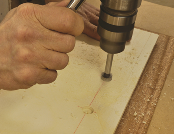
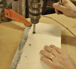
5. Drill both locations with a ¾" Forstner bit to a depth of 5⁄16".
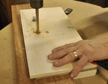
6. Clamp the plates together and drill two 25⁄64" holes.
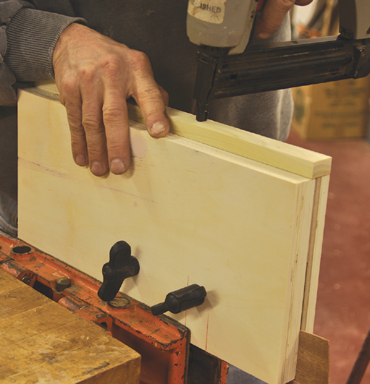
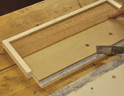
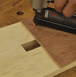
7. With the plates still assembled, tack and glue the ½" x 1" material to the edge of the bottom plate.
8. Paint the surfaces that will come in contact with the stock with a non-skid coating.
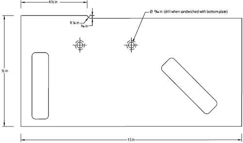
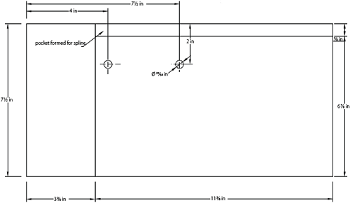
D. Bottom Plate Pocket and Boring
Layout the centerlines for the two holes that pass through both plates.
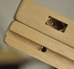
The Bottom Plate
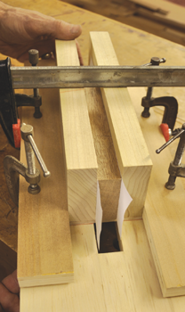
Set the template plate aside for now and go back to the ½" plywood (7½"x 15") that was cut out earlier for the bottom plate. Cut out two pieces of ¼" MDF, one at 33⁄8" x 15½" and another at 67⁄8" x 115⁄8", and attach these to the bottom plate as seen in drawing D and photo 3. The blank space left will form a pocket to hold and register the spline stock.
Boring the Holes for the Bolts
Keep in mind that two 3⁄8" by 2" bolts will be used to hold the two plates together. It is important that their relative locations be precisely located. First, take a piece of material that is about 1⁄16" thick x 3" x 15" and laminate it to the bottom plate opposite the spline pocket. A good source for 1⁄16" material would be either plastic laminate or veneers of that thickness. Before going on, flush trim any material that might be overhanging the bottom plate. Now turn the bottom plate over so you are looking at the face opposite the laminations. Referring again to drawing D, layout the centerlines for the two holes that pass through both plates. With a ¾" Forstner bit, drill both locations to a depth of 5⁄16". Be sure to place some 1⁄16" material under the thinner portion of the plate for support.
Now, assemble the top and bottom plates together in their respective positions. Place a 1⁄16" spacer between the two plates where it is needed for support. Clamp the plates together and drill two 25⁄64" holes using the center drill point from the previous hole as registration points. A 3⁄8" bolt can be inserted into the first hole drilled to insure common registration.
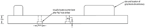
With the plates assembled, clamp them together in a bench vice and tack and glue the ½" x 1" material to the edge of the bottom plate as shown in drawing B and photo 7. Next, using a non-skid coating material such as Skid-No-More by Evercoat, paint the surfaces that will come in contact with the stock, as shown in photo 8. Be sure to scrape away any material that may form in the corner of the bottom plate and prohibit correct registration of the stock.
9. Clean up the corners of the bottom plate.
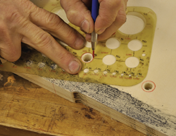
10. Center and trace a 5⁄8" circle around the two holes.
11. Countersink to a depth of ¼".
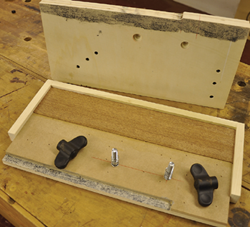
12. An inside view of the jig with compression springs in place.
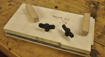
13. The finished jig.
E. The Slotting Jig
Going back to the inside face of the template plate, use a drafting guide to center and trace a 5⁄8" circle around the two holes. (This could have been done along with the other boring if I had not spaced out.) Visually registering the locations and using a 5⁄8" Forstner bit, countersink to a depth of ¼".
Assembly
For the finishing touches, attach a couple of handles to the top of the template plate. Size and locate them in such a way that is comfortable to you. Next run two 3⁄8"x 2" hex head bolts from the bottom side of the bottom plate. The head of the bolt should recess and clear the bottom of the plate. Next place ¾" x ½" compression springs over the bolts. The counter-bore on the inside face of the template plate will accept the compression springs when the jig is assembled. To finish the jig, place the template plate on the bolts and secure it to the bottom plate with two 3⁄8" wing nuts.
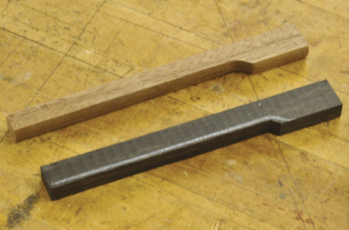
The Slotting Jig
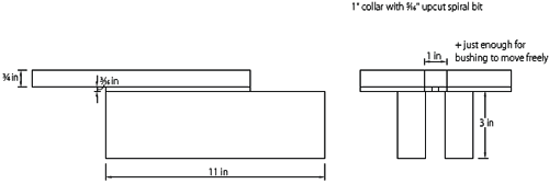
This next jig is for routing the slot in the edge of the top for the ebony.
Cut out the following parts for the jig: two pieces of wood at 1" x 3" x 11", two pieces of ¾" ply at 3" x 11", two pieces of ¾" ply at just a hair over 1" wide and exactly 3" long, and one piece of 3⁄16" thick material 7" x 79⁄32". Sometimes 5mm ply can be found that is marketed as ¼", but actually measures out at very close to 3⁄16". If stock material is not available then you will need to sand down some ¼" MDF. (Tell your wife you need to buy a drum sander). Save small pieces of the 3⁄16" material for later use.
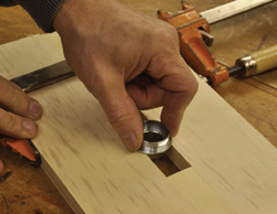
14. Dry-clamp the routing platform together and test a 1" bushing for ease of movement.
15. Assemble and glue the four pieces that make up the “routing platform.”
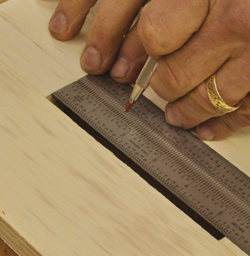
16. Mark a line 115⁄32" down from the end of the opening.
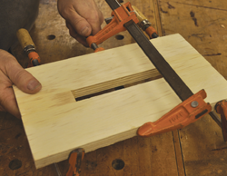
17. Laminate the already cut out 3⁄16" material to the face of the glued up parts, registering with the drawn line.
Clamp together the two pieces of ¾" x 3" x 11" ply with two small pieces of ¾" ply that are just a few thousands over 1" wide and exactly 3" long. Test fit a 1" router bushing for ease of movement in the opening formed between the larger pieces of ply. If necessary, re-size the small pieces of ply until the bushing moves easily with a minimum of slop.
Next, using biscuit or domino if available, glue the four pieces of ply together to form the “routing platform.” The small 1" wide pieces should be flush with the ends of the larger pieces to form a 5½" open space in the middle.
Now, mark a line 115⁄32" down from the end of the opening, then register the already cut out 3⁄16" material with the newly drawn line and attach it to the routing platform.
Theoretically the 3⁄16" material should be flush with the two sides and the back end. If it overhangs at any point, flush trim it to the ¾" material.
Precise registration of the “clamping plates” to the “routing platform” is critical to the success of the jig. To accomplish this, take a 7⁄8" thick piece of wood (same thickness as the top) and sandwich and clamp it along with two pieces of printer paper between the two pieces of 1" x 3" x 11" wood (clamping plates) that were previously cut out. Now, place the clamped assembly on the backside of the routing platform and flush with the leading edge of the 3⁄16" material. Measure for and cut two equal pieces of scrap material to fit flush along either side of the clamped assembly and flush with the outside edges of the platform, and then clamp the two pieces of scrap in position. Turn the clamped pieces over now and secure the routing platform to the clamping plates with about 3-4 wood screws each.
18. Use scrap material to fit flush along either side of the clamped assembly and flush with the outside edges of the platform.

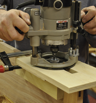
19. Clamp the slotting jig to the stock and route a test groove.
The clamping plates should now easily slip over the top and hold it securely in position with a single clamp. The resulting route should place a slot roughly in the center of the top’s thickness.
Blanking out the Ebony Spline
With the jig making out of the way, we can now move on to making some progress on the detail itself. First, the exact width of the route produced by the slot jig needs to be determined so the ebony can be exactly sized. Set up a plunge router with a 5⁄16" up-cut spiral bit and a 1" collar. Mill out some scrap stock to exactly 7⁄8" thick, which is the same thickness as the top. Clamp the slotting jig to the stock and route a test groove. Be sure to make two final passes; first with pressure on one side of the collar opening and another with pressure towards the other side. If you remove the router from the jig and then replace it and continue routing, make sure you note the router’s orientation. If the router is turned side to side, any inaccuracy in the centering of the collar will cause the slot to enlarge.
Mill some scrap wood down in thickness until it produces a “light friction” fit in the test groove. With a satisfactory fit, and on the same thickness setting, mill out several more pieces of scrap, as well as the ebony, to a width of 5⁄8" and 51⁄8" long. Mill one of the scrap pieces to about 1" wide. Leave the router set up with the 5⁄16" bit and the 1" collar.
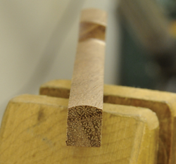
Using the Ebony Spline Shaping Jig
To start with, mark a line down the center of the thickness of the 1" wide scrap piece that was just cut out and register it in the corner pocket of the bottom plate. Secure the stock firmly with the wing nuts.
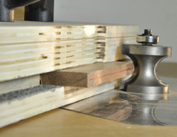
Next, in a router table, set up a full bullnose ½" radius bit with a 5⁄8" radius bearing (Amana # 51572). The center of the bit’s radius must line up exactly with the center of the stock in the jig. Place a light source on the backside of the router table, then line up the jig so the line down the center of the stock centers itself on the crescent of light that defines the arc of the bit.
Be cautious when making the first router cut. If not done properly the jig can be grabbed and violently thrown. It is not necessary to route a path all the way to both ends of the jig. It is necessary only to clear, with a little margin, the normal pathway of the bit. If you have any apprehensions whatsoever ask for experienced help. Resting the jig firmly against the fence, pivot the jig into the cutter.
To make the initial cut, firmly rest the trailing end of the jig against the fence and then pivot into the cutter. The bearing should only make contact with the edge of the jig that faces the fence. If the bit grabs the leading edge that is not parallel with the fence it will most likely jerk and throw the jig.
The initial setting is unlikely to be perfectly centered. Examine the stock from the end to determine if the bit needs to be adjusted up or down to center the arc on the stock.
20. Center the stock and the bit.
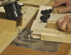
21. To make the initial cut, firmly rest the trailing end of the jig against the fence and then pivot into the cutter.
22. Determine if the bit needs to be adjusted up or down.
23. Using one of the test pieces, trace the outline onto the ebony parts and band saw some of the extra material away.
With the bit height adjusted correctly, take one of the test pieces and trace the outline onto the ebony parts and band saw some of the extra material away. Be careful not to remove too much material from the ebony, just enough to reduce the chance of blowout. Now machine the ebony blanks and set them aside.
Making the Breadboard Top
The ebony spline detail is intended to visually enhance traditional breadboard construction. There are a number of suitable techniques used to construct the breadboards and you are free to use what works best for you. I will however, very briefly, cover the matter for those who would like some guidance.
The idea behind the breadboard is to control the warpage in solid wood construction. The technique takes advantage of the fact that wood is more likely to warp and move in the cross grain direction, and much less likely in the long grain direction. To put this in practice, a relatively narrow strip of solid wood (breadboard end) is attached with its long grain at a right angle to the solid wood panel (core) in its cross grain direction. The matter is complicated by the fact that the core will move across the joining point with changes in relative humidity, while the breadboard end will not.
To start, first route a ¼" x ½" deep slot (centered on the core thickness) in both the core and the breadboard end referencing from the bottom. In the core, glue in a ¼" x 1" wood spline with the grain following the direction of the core. The old rule of thumb allows for 4" of cross grain glue-up. With the center 4" of the breadboard end glued directly to the core, the core’s movement is restricted from the center out. In other words, the core’s movement will be controlled so it only moves half the total amount on either side. Further out from the center (every 4-6 inches—not evenly spaced per side but symmetrical from side to side), #10 x 2½" pan head wood screws are used to secure the end to the core. To allow the screws to move, leave about a ½" opening in the spline. Square and rectangular ebony plugs on the outside edge of the ends cover up the screw heads. Calculate the depth of the plug holes to allow the screw to penetrate the core (beyond the spline slot) to at least 1". To allow the screws to shift and flex as the core moves, pre-drill for the screws into the breadboard end, then counter bore with a ¼" bit leaving ¼–3⁄8" of meat. This method should be adequate for mahogany tops of less than 30" wide. For tops wider than 30" (more movement), make a lateral slot for the screw to move in.
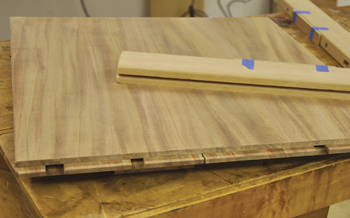
The thickness and length of the breadboard end is dictated by the size of the core. The end is 1⁄8" thicker than the thickness of the core and 3⁄8" (3⁄16" proud at either end) longer than the core is wide. The width of the end is normally between 2¼" and 2 ¾", but can be larger depending upon the scale of the design. When attaching the breadboard end to the core, use a piece of 3⁄16" (the extra pieces set aside from building the routing platform) material to gauge the overhang.
All exposed corners of both the core and breadboard end are rounded over 1⁄8". When sanding, add a little extra softening to the radiused corners on the end-grain face of the breadboard end, giving it sort of a “worn” look.
When gluing the breadboard ends to the core, clamp the glued up center section, then one at a time, clamp near the screw locations and run the individual screws.
24. Pre-drill to allow the screw to flex.
25. Glue the spline into the core leaving a ½" path for the screws, then glue the center 4" of the spline to the breadboard end.
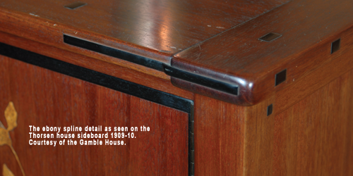
Rounded “worn like” edges on the breadboard of the Thorsen server. William R. Thorsen House, 1909–10. Courtesy of the Gamble House.
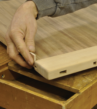
26. When attaching the breadboard end to the core, use a 3⁄16" spacer to gauge the amount of overhang.
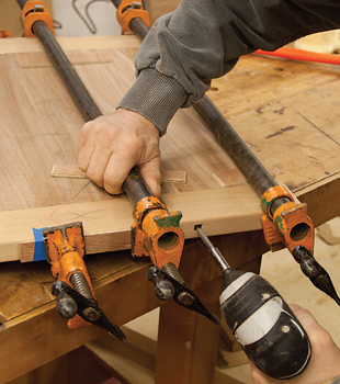
27. Clamp and screw the end to the core.
28. Test the depth of cut.
29. Register the 3⁄16" material on the underside of the routing platform against the breadboard end.
30. Register the 3⁄16" material against the breadboard end and clamp.
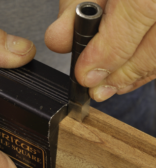
31. Register one face of a 5⁄16" square hole punch (available at Lee Valley) square against the saddle with the opposite two points inside the slot.
Routing the Slot
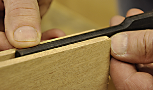
First, the depth of cut must be determined. To do this, clamp the slotting jig to some 7⁄8" thick material and set the depth initially to roughly 5⁄16" deep. Route a test slot, then test the depth with one of the ebony splines. Ideally about 1⁄16" of the shoulder should be showing.
With the depth set correctly, route the slots in the top. Be sure to register the 3⁄16" material on the underside of the routing platform up against the breadboard end. Next, the rounded ends of the routed slot need to be squared up.
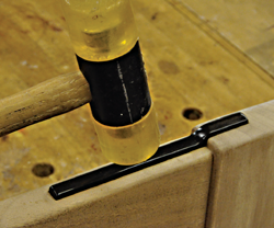
Line up a Veritas Saddle Square, or a small square, precisely at the end point of the slot. Register one face of a 5⁄16" square hole punch (available at Lee Valley) against the saddle with the opposite two points inside the slot. Push the two points of the punch nearest the saddle into the wood, remove the saddle, and drive the punch home with a steel hammer.
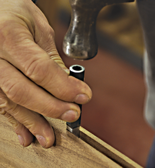
32. Using a steel hammer, drive the punch home.

33. Polish the face of the spline.
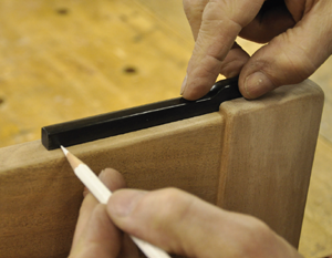
34. Mark the spline length.

35. Slightly back bevel the two ends.
Installing the Ebony Spline
Start by sanding the rounded face of the spline to 600-grit, while very slightly easing the corners. With white rouge polishing compound and a buffing wheel set up in the drill press, polish the face of the spline. Next line the spline up with the routed slot and mark the length of the slot on the narrow end of the spline. The wider end of the spline is already sized to suitably mimic the drop down from the breadboard end. Trim the spline to fit with a light 1⁄64" gap. Then ease and buff the just trimmed end. To avoid hanging up on the ends of the slot, slightly back bevel the two end faces. Next, in order to avoid bottoming out in the slot when the core contracts, relieve about 1⁄16" of material from the inside at the wide end.
Spread a little glue in the core side of the slot only. When the core expands and contracts the spline is designed to float in the breadboard end side of the slot; because of this, make sure no glue is applied there.
To finish off, tap the spline in place with a plastic headed mallet. Also, to aid in letting the spline float in the breadboard end side, position the 1⁄64" gap at that end.
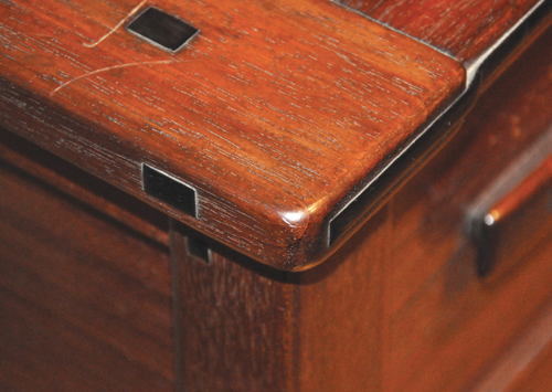
Of the numerous Greene & Greene details emulated by today’s woodworkers, the breadboard spline is among the most widely celebrated, and rightly so. It is a work of genius! It transforms the humble breadboard to the level of high art. It is something that begs to be touched and the silky smooth feel of polished ebony does not disappoint.
36. Tap the spline in place.
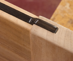
37. Position the 1⁄64" gap at the breadboard end side of the slot.
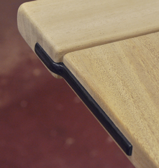
38. The ebony spline detail.