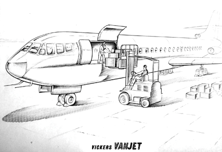
Vanjet Studies.
The long and convoluted Imperial Airways and BOAC narrative formed the roots of the foundation of the VC10 story. But the true plot of the VC10 airframe was shaped in a scenario that is best framed by one word: Vanjet.
The Vickers Vanjet studies were a 1950s series of on-paper jet airliner designs that drew upon the Viscount’s brilliance in order to frame a jet future. The process was complicated, but actually took place in just five years. Vickers had tried a jetpowered iteration of their Viscount as early as 1949 when it mounted a Rolls-Royce ‘Tay’ turbojet in a pod under each (existing) wing of a Viscount airframe. That idea came after Vickers had pondered if two or even four smaller ‘Nene’ jet engines could be fitted to their Viking airframe on underwing pylons. Prior to that – in late 1945 – the Nene-powered Avro Lancastrian was not quite the first true jet ‘airliner’ in that it had two of its four piston-powered engines replaced with jets, but never entered service other than giving joyrides. Six jet-converted Lancastrians were built and flown, and they latterly flight tested the Rolls-Royce Avon. But the jet Lancastrian was not a production machine.
Therefore, it can be argued that the Vickers-Armstrongs Nene-powered Viking, allotted the Ministry code of VX 856, soon to be registered G-AJPH, was, upon its first flight on 8 April 1948, Britain’s first true jet-powered airliner, even if it was a converted piston-powered wartime airframe.
The Nene Viking was ordered by the Ministry of Supply and took a Vickers Viking airframe and used its great strength to provide a mount for two early Rolls-Royce Nene turbojets, each of 5000lbs/2269Kg thrust. Newly sculpted jetengine pods were grafted onto the existing wings with minimal local structural changes being required – notably thicker gauge metal skinning to the wings and an added metal skinning to the elevators. A new four-wheel main undercarriage design retracted up into the engine pod (besides the jet pipe), with two short undercarriage ‘stub’ legs per side. On 25 July 1948, the Nene Viking flew twentyfour passengers from London Heathrow to Paris Villacoublay in 35min 7sec – less than half the normal flight time for a propeller-driven Viking.
From this successful research airframe came Vickers next iteration of the jet future of the airliner; for, by fitting two of the 6,250lb/2,835Kg rated Tay engines – a developed version of the Nene – to an early model Viscount V630 airframe (redundant after Rolls-Rolls managed to uprate the Dart turboprop used by the Viscount and thus permitting an airframe stretch), something that was a major learning step was built. Again the Ministry of Supply was behind the project and the Tay-powered Viscount was designated as a V663. Like the Nene Viking, the Tay Viscount (first flight 15 March 1950) used a twin-stub leg, twin-wheel undercarriage, under each main wing, retracting beside the jet pipe. The Viscount’s superb aerodynamic design and strength meant that again, no significant structural upgrades were required for the jet conversion, despite the increased speeds and stresses. Of great note, the slippery Tay Viscount seemed to be faster than the prototype DH Comet 1 – both airframes being flown at the 1950 Farnborough Air Show. The Tay Viscount was used as a research machine, principally for developing a Bolton Paul design for a powered control system that was to be deployed in the Vickers Type 660 bomber – the Valiant. The Tay Viscount was then used to test-fly the world’s first electronic flight control signalling system. But the key factor was that in the Vickers Tay Viscount, a capable, high-speed airliner-type airframe came to fruition.
Indeed, the Tay Viscount was the most manoeuvrable, fastest-climbing of the early 1950s jet-converted research airframes. Given that it was based on the 1946 design origins of the Viscount, this speaks volumes for the talents and strengths of the Viscount product. Such strengths would manifest in the Vanjet studies that became the VC10. And a quick look at the 1960s Boeing 737 design, specifically at the engine wing-pod design, reveals that the Tay Viscount was an eerie precursor of the little Boeing’s form. But something new, a new shape was now required.
Rear Engines and Clean Wings?
Why rear-mounted engines? Surely the lowest drag was to be achieved by burying the engines in the wing roots, as had been suggested by the Comet, the V1000, and would be seen on the Vulcan, Valiant and Victor? But the wing root location also gave rise to complex, but solvable structural issues, cabin noise and potential risks from fire, and fuel tank proximity in the event of engine explosion or crash landing – or so said arguing theorists in each camp!
So design fashion soon favoured the ‘podding’ of engines – either slung under the wing off pylons, or on a short pylon-stub wing at the rear of the fuselage, a la Caravelle. Vickers decided to pursue the rear-mounted engine pylon-stub wing configuration. The reason for this were the significant adverse drag rises and losses in wing lift coefficient that hanging the engines off the main wing in underslung pylons gave rise to. Engine pods and their pylons disrupted airflow over the leading edge and created ‘plumes’ of displaced and disturbed airflow around and over the local area. Any leading edge devices would have their function interrupted by the pylons, and trailing edge flaps would need to have gaps in their area to allow for jet exhaust from the podded engines. Above all, an unnecessary rise in drag, and a drop in ‘span lift distribution’ efficiency were the vital demerits of the under-wing pylon/pod configuration. Engines on the wing also directed thrust, vibration, noise and distress onto the rear fuselage skin and windows – all of which could be felt and heard in the cabin. ‘Buried’ engines, as in the Comet and Valiant, were not immune from such effects either.
But American designers insisted that engines slung off the wings were much safer in a crash than rear-mounted engines and fuel lines. But were they correct? Would big, underwing-mounted jet engines, placed so close to the wing, really decide to conveniently ‘break off ’ cleanly in a fire or ground impact, and get their hot and dangerous parts away from the airframe? This was what American designers believed, but they were proved on occasion to be incorrect; big, hot and heavy jet engines hanging off the wings were likely to smash into the wings and rupture the main fuel tanks in those wings, or spray hot turbine parts onto the wing tanks – resulting in a fire and structural failures of the wings towards the wing root. In many examples, including the BOAC Boeing 707 fire at Heathrow in 1969, the British Airtours 737 in 1987 at Manchester, and the British Airways Boeing 767 fire at Las Vegas in 2015, the exploding wing-mounted engines created the subsequent fuel tank-fed fires and airframe damage. So the claim that wingmounted engines were safer in a fire, or a crash landing, was proven in most circumstances to be a myth. And surely, a correctly designed rear-mounted engine in a reinforced rear ‘cradle’ was much stronger and such engines might not break through the fuselage or snap off. Only in the circumstance of in-flight fire and engine separation could such wing-mounted engines be deemed to be ‘safer’ – provided they did not rupture and ignite the wing fuel tanks as they burned or fell off!
Some designers argued that, just as with closely-paired wing root mounted engines, any paired or closely aligned rear engines could have adverse effects upon the neighbouring engine in the event of turbine blade breakage or main turbine compressor burst. Surely, adequate armour plating and firewall design could lower the risks of such possibilities? And at least they were not inches from a main fuel tank.
Nevertheless, a wing/engine design configuration debate raged in the 1950s. Paradoxically to the argument, while the 707 and DC-8 might have wing-pylon mounted engines, the 727 and the DC-9, from the same manufacturers, and their previous pylon preferenced certainties, did not.
Boeing had deployed German research findings into swept-wings and pylon or podded engine layouts into the B-47 bomber, which featured the first major iteration of a 35º swept-wing airframe powered by underwing podded engines. It looked like a huge success, but the drag-rise from the pods and the lift-loss penalties were considerable for the B-47, with Boeing wind tunnel data indicating notable losses in span lift distribution. The loss of span lift distribution efficiency was said to result in a denuded efficiency figure and the engine pods created eighteen per cent of the entire airframe’s total parasitic drag figure.1 And surely speed and range would be compromised by such drag rise and lift loss as seen with underwing podded engines? There were also in-service structural issues with the wing. If Boeing was going to repeat the configuration for the 707, a little learning would have to be applied. Indeed, Boeing had to devote large amounts of resources to fine tuning the 707s engine pylon design; for the DC-8, Douglas had to take several bites at the design apple, with major design modifications being made during series production to solve drag issues stemming directly from the wing aerofoil and pylon and pod design combinations.
Vickers decided that the aerodynamic losses associated with wing-pylon mounted engines, particularly in terms of lift coefficient, were far too serious for an airliner design for which the key need was extra lift to deal with difficult runway environments. To that end, Edwards was initially said to be very keen on retaining the Valiant and V1000 style wing root engine layout with its exceptionally beneficial aerodynamic advantages, but a clean sheet and a new design solution was to prevail. Such were the factors and choices as to how and why Vickers eschewed the 707 and DC-8 style of engine-mounted engines, abandoned the wing root engine layout, and pursued the VC10s expertly designed ‘clean wing’ configuration. Such expert design work would have much lower drag than wing-mounted pylon-pod engine ‘barnacles’, and also deliver noise reduction in the cabin.

Vanjet Studies.
The demanding VC10 specification lift-coefficient needs drove the decision to put the engines at the back and left the wing to deliver as much lift as could be generated.
Teutonic Design Ideas
As previously stated, the first known suggestion of an externally rear-mounted jet engine (on stub wing/pylon) came from Hans Multhopp’s 1944 design studies in Germany for the Focke-Wulf FW283 athodyd-powered jet airframe; however, that machine was not built, but its designer was seized and taken to London in May 1945, spent time at the RAE Farnborough was then to be gifted to American aviation under Operation Paperclip. Multhopp was the creator of the T-tail, swept-winged fighters, rear-mounted jet engines, and ‘lifting-body’ research. At Farnborough, Multhopp, and colleague Martin Winter, designed a swept-winged interceptor which the subsequent EE. Lightning very closely resembled.2
The Dornier concern had devised fuselage and wing-mounted jet engine pylons and pods in 1943, and as with Multhopp’s works, such ideas were not wasted by the Allies.
However, we can, beside the DH Comet 1, evidence Vickers 1940s studies into jet airline design as the origins of British jet airliner success and rear-mounted engines. Perhaps, somewhat aping Multhopp’s 1944 FW 283 athodyd design, with its rear engines on fuselage mounted pylons, Vickers had designed a rear-engined jet airframe in the form of a pilotless remotely-controlled bomber project entitled SP.2 in 1951. Of note, the company had earlier mounted a small jet engine on a stub pylon from the rear fuselage of a Wellington bomber in 1947. Proof positive then that, from immediate post-war days, Vickers were thinking of a wider future and rear-mounted engines. The completion, in late 1949, of the Tay Viscount underlines the point, because from thoughts of the Tay Viscount came Vickers design proposals for more advanced jet airliners – rear-engined ones.
The Vickers Commercial, or ‘VC’ series, saw the Vickers Wellington-based Viking airliner cited as the VC1, the Viscount as the VC2 and a VC3 stemming from a developed Varsity proposal which was not made. In 1946 came the Vickers Commercial VC4 – a study into a potential transatlantic civil jet airframe – which although never made, put down some early research findings. In 1951 came the VC5 as a projected long-range passenger variant of the Valiant V-bomber and in 1952 came a suggested BEA medium-range version as the VC6; neither being proceeded with. The legacy of these designs manifested in a V1000-based VC7 derivative, which died in 1956 with the V1000 project.
Due to the impending Douglas DC-8 and DC-9 numerical branding, Vickers sidestepped these numbers and its next actually produced ‘VC’ would be the VC10; somewhat confusingly a design that stemmed from the ‘Vanjet’ studies which had to some extent mirrored the VC2 origins – the Viscount. Of interest, a reverse-engineered, scaled-down VC10 known as the VC11 as a proposed mediumhaul Vanjet reiteration, was mooted in 1959–1960, which was in effect Vickers last project (stillborn) prior to BAC amalgamation in 1960.
Little known is that Vickers had, in 1952, devised an idea for a small or ‘little’ twin-jet of fifty to seventy seats potential, for a specific and difficult airline requirement – that of short, regional, or inter-State flights in Australia by domestic airlines. It was a step on from the jet-powered Viscount and its potential was later mirrored in the success of the similar Fokker F28 airliner – notably in Australia.
A ‘Little Jet’ from Down Under
As in Africa, Australia had difficult operating runway requirements (hot temperatures and short tarmac strips) and large payload capacity needs. Could a high-lift wing, twin-jet be cheaply built and sold to the Australians for around £500,000 per machine? Vickers design team called this idea the ‘Little Jet’, and in it lies a wider context that mirrored themes within the ‘Vanjet’, for the ‘Little Jet’ needed a clean, thin-section wing for better runway performance in the outback heat and for high-speed short sector timings, and that meant rear-mounted engines and perhaps a T-tail. Was this the gateway to subsequent thoughts? The likely increase in jet turbine size and front-fan compressor design was soon realised to be the death-knell of the wing-root buried jet engine. New turbofans would be large and have fan blades rotating in their inlet airflow ‘mouths’ and rear compressor, and even ‘aft fan’ sections. There would only be three places that they could be mounted on an airframe – above or below the main wing on pylons, or hung off the tail. These were the combined factors that led to Vickers studying the rear-engined jet. The Caravelle was being designed at the same time (1953–1955), but it relied on a big wing area and low-wing loading for its lift coefficient – not on a panoply of leading edge and trailing edge lift devices. Neither was it T-tailed; it was, however, uniquely, rear-engined.
The Vickers Vanguard was BEA’s new short/medium-range tool, designed and delivered as requested, and yet now BEA was touting around the British aircraft manufacturers for a similarly sized regional jet it had eschewed when it requested the Vanguard in the first place! Engineering men inside BEA – such as Beverley Shenstone – were powerless to stop what became the Trident’s rescaled downsize, the only option being to resign, which would be a high price to pay. So the development of a smaller British twin-jet or tri-jet of fifty to seventy seats was fraught with layer upon layer of unintended consequences. Bizarrely, Trans-Canada Airlines (TCA), forerunner to Air Canada, made the most of its ‘winterised’ special edition Vickers Vanguards and the 139-seat stretched Vanguard II model with a weight of 141,000lbs. BEA ordered six such airframes – labelled as Type 951s, but TCA even operated its near 2,000miles range Vanguards on long-haul Canadian routes. We might wonder in hindsight if BOAC could not have persuaded Vickers to create a long-haul extra-fuel tankage Vanguard for a BOAC long-range Vanguard serving London-Rome-Cairo-Nairobi-Salisbury-Johannesburg by 1959, as a Britannia alternative.
Hunting, de Havilland, Bristol and Handley Page, were all creating proposals for a small, fifty to seventy seat jet airliner with the potential to be stretched to a medium-range 100 seater. Naturally Vickers, having supplied BEA’s Vanguards, wanted the business. So Vickers began to think about just such an airliner – one not so dissimilar from recent ‘Little Jet’ ideas, and which would become the twoengined and three-engined variable task Vanjets before the BOAC requirement would dominate, and Vickers would leave the regional or intra-European twin and tri-jet of BEA formula for others to frame. Curiously, in 1959, a VC11, as a down-scaled post-VC10, would be a strange, reverse-engineered suggestion for the BEA regional jet, but it was abandoned as Vickers went for the BOAC longhaul order and amalgamation of the industry saw other projects given preference in the wheeling and dealing that created the British Aircraft Corporation in 1960.
Advanced Projects Office
From Vickers SP2 and ‘Little Jet’ sketches, circa 1952–1953, came plans for such a jet airliner with a swept tail, and from that, in early 1955, came sketches for having the axial-flow jet engines (Rolls-Royce Avons) mounted at the rear – in the fashion of the pioneering Caravelle that would arrive from Sud Aviation in Toulouse in 1955. From these plans came an idea that the twin-engined version might serve BEA, and a three-engined version (the third being a centrally mounted, fin-intake S-duct configuration) to serve BOAC – although in the end the tri-jet would become a BEA context and the BOAC suggested airframe be given four engines. The early sketches (see below) form the basis of the futuristic Vickers Advanced Projects Office civil jet thinking. Soon, a Viscount-base was discarded, and the larger fuselage of the new Vanguard substituted as the base unit. Here arrived, in 1954–1956, the true ‘Vanjet’ studies.
In a drawing dated 11 June 1956, a Viscount fuselage was extended by 40ft, mated to a Vanguard wing and carried four Rolls-Royce Verdon engines. A Mk1A version carried ‘slipper’ wing-mounted fuel tanks. Next came versions using the Vanguard fuselage, and by Drawing Number 79924, a swept-wing of Valiant provenance had been added to the design. At one stage the thought of using the main wing from the Supermarine Scimitar was mooted (Supermarine being a Vickers subset). But a more advanced and more expensive version was mooted in Drawing Number 79925 when a completely new 35º swept-wing was envisaged. Before long, earlymodel ‘Conway’ turbofan engines were suggested, deleting the axial-flow Avon and adding a significant performance boost and the possibility of more than seventyfive seats in the cabin allied to the medium-range payload formula. By this time, swept main wing and swept vertical and horizontal tail surfaces were set. Some iterations had mid-mounted tailplanes as in the forthcoming Caravelle, one had a T-tail and another had the tailplane mounted rather vulnerably underneath the rear engines. Cabins were seen as four-abreast, and a unique combined four/five abreast stepped configuration as ever-increasing capacity options. Rear airstairs were also suggested, and the twin and tri-jet Vanjet concepts had the air of real, tangible success.3
More Australian and Canadian Suggestions?
As the two and three-engined variants firmed up in the Vickers drawing office in 1956, the company had talks with not just BOAC and BEA, but also with existing Viscount customers such as Trans-Canada Airlines (TCA) and with Trans-Australia Airlines (TAA). Of significance, Canada’s TCA was a Vickers customer and talked closely with the Vickers design team when ‘winterising’ Viscounts and Vanguards for Canadian operations, as well as suggesting new ideas. TCA had been instrumental in selling the Viscount in America. Canada also had its own manufacturing subset, Vickers Canada Ltd, as well as Avro (A.V. Roe) Canada. On the other side of the globe, Australia’s TAA had previously approached Vickers with an idea for a ‘super’ Viscount – a machine with a longer fuselage mounted on a Viscount wing. (The Vickers Vanguard and the Lockheed Electra both might qualify as super-Viscount themes.) Such a machine would add payload on difficult Australian domestic routes. Without realising it, TCA’s ideas, and then TAA and its Jim Dailey, who proposed ideas to Vickers, had in fact presaged the Vanguard and a developed Viscount/Vanguard concept – maybe even one with jets.
BEA’s chief engineer, the influential Canadian, Beverley Shenstone (whom had been very well known to Vickers after they had offered him their top design post in 1946, had been close to the Viscount and Vanguard designs, and up to 1946, had worked at the top of Canadian aviation and in Canada’s Government), was also closely involved in these design lineage steps. Developing the Vanguard was in hand – but giving it jets came a bit later. New thoughts were required.
Of interest, an article in New Scientist, on 9 April 1959, categorically cited BEA’s chief engineer, Beverley Shenstone, as providing design guidance to the use of the T-tail configuration in the DH Trident and the Vickers VC10. Shenstone believed in tail-mounted engines and the consequent T-tail design and persuaded de Havilland to accept it, and Vickers to look at the concept’s advantages. His private correspondence with Stanley Evans and others in the industry at the time, further evidences that Shenstone was a major influence behind the scenes towards the T-tail configuration gaining ground for the Trident and the Vanjet/VC10. He had, of course, been very close to Edwards and his team during the Viscount development. So Shenstone appears to be a VC10 sub-influence, but we might suggest that George Edwards (initially favouring wing root-buried engines) was getting there anyway without Shenstone’s missionary work!
Australia’s Mr Dailey also told Vickers that TAA would be considering Douglas DC-8s in order to ‘keep up’, which must surely have flagged up a warning at Weybridge, as well as reminding everyone about the potential of the V1000 project.4 Did it not prove that ‘Little Jet’ had had potential – as its progeny, the Vanjet might?
Other major airlines were in conversation with Vickers about its Vanguard as jet derivatives. The whole ‘Vanjet’ project was beginning to take on a viable commercial potential. On 25 June 1956, Vickers’ Mr Lambert replied to an enquiry (by telex no less) from old Canadian friends at TCA and their Mr Glenn, who had enquired about the weight penalties of increasing the fuel capacity of the Vanjet to 55,000lbs. Vickers reply was that the ‘penalty’ would be 600lbs; was the Vanjet truly beginning to look viable?
Typical Vickers over-engineering was seen in many of the Vanjet design studies, this included a T-tail with not just a ‘bullet’ fairing at the fin-top, but also a ventral ‘plate’. Designers use one or the other as an aerodynamic device to tune airflow at the top of a tail fin, but both was overkill, surely?
After intensive maintenance attention to the Viscount’s wing spar – regular ‘filleting’ had had to be carried out to keep ahead of potential trouble – Vickers had moved towards a multi-spar wing ethos; as seen in the Vanjet and resultant VC10.
Thousands of man-hours went into Vickers specifications for its jet airliner. Range, max payload, airfield details, runway performances, climb rates, fuel flows, flap angles, lift-coefficients, wing loadings, and the original ‘clean’ wing studies all began here. Money was saved by the suggested use of Vanguard cockpit windows and frames (VC10s would reuse the two main Vanguard windscreen panel designs), and the use of Valiant toolings in the wings and fuselage wherever possible. For some months, the basis of Vanjet ideas used the Vanguard’s ‘doublebubble’ fuselage as a direct transfer of costs and paid-for tooling. This was latterly abandoned for a completely new fuselage structure, but costs went up and you could not lay responsibility for this on anything but Vickers own process and decisions.
A lot of work went into designing a safe ‘cradle’ rear engine mounting system for the two and three-engined Vanjets. Thus included designing strong, transverse engine mounting beams across the rear fuselage (they were to be drop-forged alloy) and adding triangulating bracing struts to locate the engines and their thrust actions upon their mountings. Bracing in the third, ducted central engine, and feeding it from a fin-intake S-duct, provided a major challenge. Boeing and de Havilland would soon be studying the same issues for their tri-jets respectively. Vickers Vanjet research works were privately funded and a great deal hung on the outcome – jobs and lives.
The ‘Jet-Viscount Scheme’ had, by this time, become the ‘Jet Vanguard Scheme’ and then the ‘Vanjet’. The VC nomenclature was then added to the title and the studies became ‘Vanjet VC10’.
Up to fifteen ‘Mks’ of the Vanjet series were speculated in drawings and separate specifications files. A typical seventy-five seat, 1,000nm range was the baseline for the twin-jet idea and 100-seat 1,500nm or even 2,000nm options with three-engines (using an S-duct in the fin leading down to a rear fuselage mounted engine), were all on the books in the Vickers drawing office. Indeed, Vanjet Mk15 had proposed three rear-mounted Conways, a wing of 18,000sqft, a 2,500nm range from 45,500 gallons of fuel, and a payload of 21,000lbs. Here, within these Vanjet specifications, lay airliners of DC-9 and Boeing 727 potential, years before those machines came to fruition. There was even a forward fuselage, upward opening cargo door option for a ‘combi’ variant drawn up in 1954.
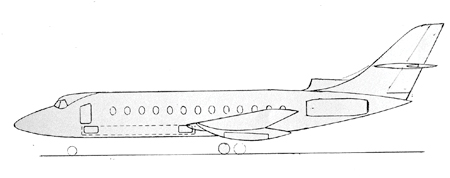
Viscount to Vanjet.

Vanguard to Vanjet.
Vickers drew up several Vanjets with two and three class passenger cabins and high density configurations at six-abreast, but with a 39inch seat pitch, not the 33inch pitch now seen across the airline standard. Fuel tankage was flexible too, the twin-jet short-range version of Vanjet might offer 1,700 miles with wing tanks only, but add three engines and a fuselage ventral tank and a 2,000, or even a 3,000 miles capable airframe resulted.
Vanjet VC10 Mk II: Drawing Series Number 79926 – Birth of the true VC10?
A medium-range three-engine Vanjet was considered – a sort of narrow-bodied DC10 of its day perhaps? Of often ignored significance is that the very first Vickers label of VC10 was applied to the three-engined, T-tailed, Vanjet study as defined ‘Vickers Commercial 10’ specification drawing. But it was not pursued in this form (see illustration). This Vanjet iteration was to be cited as Vanjet VC10 Mk II/III/IV and in drawing number 79926/sheet 3 we see a Vanjet proposal of three engines, a clean wing and total fuel capacity of 80,5000lbs or 10,450 imperial gallons as 8,450 in the wing tanks and 2,000 in the centre fuselage tank. It was in Vanjet drawing 79926 proposal that up to 108 passengers could be accommodated at a still very comfortable Economy Class seat pitch of 36 inches, that the real steps to a 100-plus seat cabin were defined.
Intriguingly, these Vanjet studies – firstly using Valiant wing and then a new, more swept-wing – all featured Dieter Kuchemann’s streamwise wing tip design – deleted from the final VC10 prototype drawings and then re-added to the first actual production series. The design drawings of the final four-engined version of the Vanjet VC10 Mk4 clearly also depict a curved trailing edge to the engine-stub wing and the beginning of the elegant T-tail and tailplane motifs.
There were over eighty paper studies for the Vanjets, all consuming not just time and resources, but Vickers own money. Rolls-Royce Avon-29 engines would give way to early Conway 10s, two and three-engined airframes would become the four-engined Vanjet. Wing sweep would go from 30º to 32.5º and the more obvious reuse of Vanguard and Valiant parts bin components would be reduced to create new, dedicated, Vanjet/VC10 parts and toolings. From here came the shape, the style, and the details of the true VC10 as we knew it. Vickers absorbed the costs and the time it took to create the new standard of airframe.
By 14 April 1954, the idea for offering a Vanjet in two-engined and in threeengined variants, with all the economies of design and build, yet providing the operating flexibility of the varying engine number, framed the true potential of the Vanjets in the world airliner market. With V1000/VC7 on the go at Weybridge at the same time, these must have been heady days – perhaps reflected by the following official statement made in a Vanjet document at the time by Vickers:
‘Technically there can be no doubt that Weybridge must be capable of designing the Mk4 and the Mk5. If we do not, who else in this country can do it better, or, who do we combine with to become a success. Failing this, once more the Americans get the last laugh’.5
But Vanjet as a three-engined machine was going nowhere because of the actions of one customer – the main potential customer – BOAC, again! What killed the three-engined Vanjet, and thus its two-engined variant? The answer was BOAC’s insistence that it would not fly the Atlantic on three engines – ever.
How different this was from the ensuing tri-jet and ‘big-twin’ jet airliners that have subsequently plied the oceans for decades. Back then BOAC was clear – four engines were demanded.
Vickers had had a simple answer to that – fit four engines to the existing design for Vanjet!
So was born the very genesis of the final Vanjet VC10 as a four-engined airliner. Here was the original, smaller, non-oceanic, VC10 concept that was the precursor to the production item. In a document proposed on 14 April 1957, the Vickers design team conjectured upon the Vanjet ‘VC’ series and their potential global markets, for here were two related airframes – not the originally proposed two and three-engined designs, but now the separate three-engined and four-engined airframes that would be of performance and economic appeal across the world’s airline routes, not just tailored so closely to one British airline and its operating requirements as to become commercially and operationally unviable upon the global stage – as the Trident was to befall as a fate.
Such dual versions of one base airframe as Vickers was now suggesting, could be vitally attractive to BOAC and BEA, and many other airlines all over the world.
Vanjet Specification B8613
In the final Vanjet idea of Specification B8613, it is the four-engined, 245,000lb/ kg airframe with a payload of 34,000lb/kg that was suggested. Here was the first four-engined idea of the previously suggested three-engined ‘Vanjet VC10’. Span was 125ft/m, length 160ft/m, height 39ft/m, gross wing area was 2,600ft/m, and a cruising speed of 580mph cited. A cabin pressure differential of 8lb/sq.in would allow a 38,000ft cruise. Wing sweep was still 30º (soon increased to 35º). Critically, the range was a healthy 3,000 miles/km and the payload almost 35,000lbs, which was in most airline accountants minds the critical point for making long-haul money.
The T-tail was high and well swept; the horizontal tail and elevators, large and effective. The leading edge devices were also large and the wing clean. Use of Vanguard cockpit window tooling was latterly discarded except for the two main panels, resulting in the definitive VC10 windscreen and cockpit side window design motifs. The engine nacelle/stub wing design was also highly advanced to near VC10 production status. The use of a Vanguard ‘double-bubble’ or twin-lobed fuselage had by now been discarded, and the expense of a new circular-section, keel-built, heavily reinforced fuselage approved.
This was the four-engined Vanjet VC10 in its obvious iteration; in weeks it would be a swept-winged four-engined design with a 130-seat cabin. Here was the defining moment of significance; the clean 35º sweep wing had a large leading edge slat of long span, with a greater degree of leading edge angle than ever seen on any airframe at that time, or until Boeing’s 727 of a decade later. A military specification version of this four-jet Vanjet was framed. Here was the penultimate step to the mighty V1000 specification VC10 – one step from a production design. All that was needed were time, money, and an increase in airframe size and engine power.
The original twin-engined Vanjet could have predated its later rivals, the BAC 1-11, DC-9, B-737 or F28/100 by years, and taken sales from the Caravelle. The three-engined Vanjet could have scooped up many sales long before the B-727 dominated the world and the quality-built, but ground-hugging Trident had failed. The four-engined Vanjet became the VC10, but not without some delays.
A huge and brilliant future lay on the drawing boards. Vickers airliners were potential global masters of the airline fleet order books, with a common, low cost base (from £500,000, £750,000 and £1,000,000 per airframe respectively) range of related airliners with various engine number options, and all offering structural, operating, and maintenance similarities that could greatly reduce an airline’s costs and offer real value for money. A pilot could fly more than one version if the controls and handling were similar enough. The only difference between the airframes would be the numbers of engines fitted and any potential fuselage length/cabin capacity options chosen. Vickers could build the twin-jet with fifty seats, or a slightly stretched version with seventy seats. The tri-jet could seat eighty or 110 depending on seat pitch or fuselage length increase; the four-jet might seat 100–130 dependent on seat configurations chosen. Common cockpit, and common servicing and operating factors across the Vanjets, from twin-jet and tri-jet, would, if they had been built, have been realised long before Boeing or Airbus attempted the same.
So was set the Viscount-Vanjet-VC10 lineage.
The Vickers design department veterans say that it is vital that observers realise that the key to the realisation of the VC10 design was the process from the jet Viscount onwards. To quote one retired Vickers veteran, Dr Norman Barfield, in conversation with the author:
‘It was the jet Viscount and the way that it became the Vanjet using Valiant bits that was the origin of the definitive VC10. We got there step-by-step through all that work.’
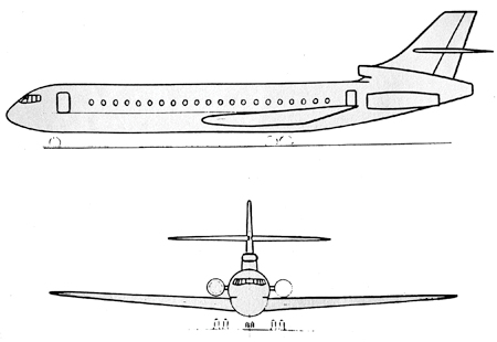
Vanjet Tri-jet.
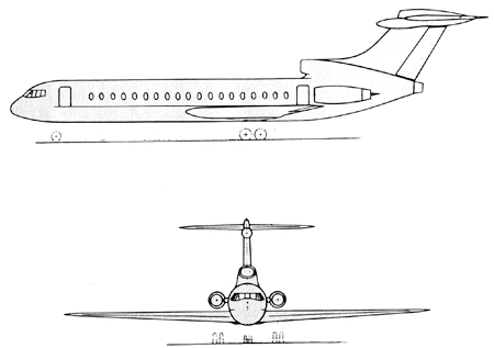
Vanjet T-Tail.
Neither should we forget that BOAC had an early look at Vickers proposals and said that one of them was ‘economically viable’.
Intriguingly, hidden in the Vanjet archives (now held at Brooklands Museum) there lies the Vanjet Mk16, which was a medium-range design with two underwingpylon mounted turbofans and a third (rear) engine buried in an S-duct under the tailfin. As such, this design presaged later 1960s Boeing 727 update studies and BAC Hawker Siddeley airbus type concepts. Remove the third tail-mounted engine and the similar shapes of the Boeing 757 or Airbus A300 twin-engined airliners became obvious. So Vanjet gave us the VC10, but it could also have given us the first ‘big-twin’ airliner after VC10 was launched. But the Vickers ‘big-twin’ was not to be.
THE VICKERS DESIGN LINEAGE 1948–1959
VIKING-VISCOUNT-VANJET-VC10
Jet Viking (Nene)
↓
Viscount
↓
Jet Viscount (Tay)
↓
Jet Viscount with Vanguard Wings with wing-mounted engines
↓
Jet Viscount with rear-mounted engines
↓
Jet Viscount as twin-jet then tri-jet with swept tail
↓
Jet Viscount with Valiant Wings as Vickers Medium-range Jet
↓
Jet Viscount/Vanguard with Valiant outer wings, then as ‘Vanjet’ cited design iterations with new wings
↓
Vanjet twin and tri-jet designs to Mk2/Mk3 + as BEA and BOAC proposals
↓
Vanjet Avon-to-Conway new engine proposals
↓
Vanjet to Mk15 designs and Vanjet VC10 BOAC four-engined proposal
↓
BOAC and RAF VC10 designs with Conway 10
↓
VC10 to V1100+ production specification with revised Conway
Note*
(a) 1950s, VC3–VC6 and ‘Little Jet’ studies in parallel
(b) 1953–1956, V1000/VC7 jet transport studies
(c) 1959–1965, VC11 as reverse-engineered scaled down VC10
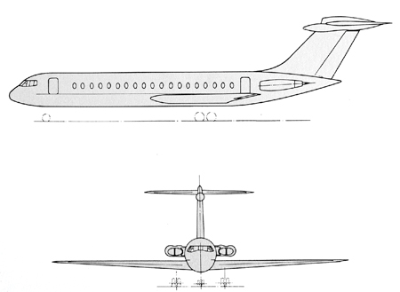
Vanjet Four Engines.
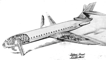
Vanjet VC10.