Your little computer can put 3.3 volts on any of its output port pins. It can deliver as much as 40 milliamperes on a pin, although that is pushing things a little far, risking overheating the little chip. That’s a total of 3.3 volts × 40 milliamperes, or 132 milliwatts of power.
While not a lot of power, it can drive small DC motors if they have light loads.
One little motor I tried spins nicely when attached to an output port pin, but since it is designed for a higher voltage (probably 5 to 12 volts), it is only drawing 13 milliamperes. That is only 43 milliwatts (3.3 volts × 13 milliamperes), which is not a lot of power, so the motor can only spin things like paper disks or small fans and would not be able to move something like a little robot car.
Motors designed to run on 3 volts or less draw more current. The little motors in pagers and cell phones that make them vibrate are designed for these low voltages, and the one I tested drew 40 milliamperes and vibrated like crazy, as it is designed to do. Small DC hobby motors designed for 3 volts, such as those you might salvage from a toy car that runs on a couple of AA cells, can drive little cars or move small sculpture parts. Bear in mind that two AA batteries in series provide 3 volts at 700 milliamperes, or 2100 milliwatts, so your little computer will not move the car very fast all by itself.
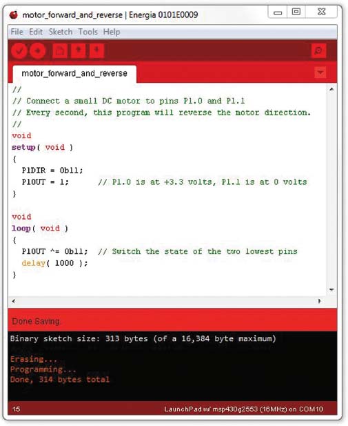
Nonetheless, sometimes you don’t need a lot of power, and the simplicity of driving the motor directly from the computer’s output pins makes life a lot easier (http://artists.sci-toys.com/motor_forward_and_reverse.txt):
The little motor will run if one of its wires is connected to 3 volts or more and the other is connected to ground (0 volts). This means you can connect one wire to ground and the other wire to any output pin and run the motor by turning that pin on, just like lighting an LED.
But DC motors can run in either direction. If you connect the wires to two output pins and arrange for one of them to be on and the other off, the current will flow from the one that is on, through the motor, to the one that is off. This will make the motor spin. Reversing the states of the pins will make the motor spin the other way. Turning both pins on or both pins off will stop the motor.
That might be enough control for many projects, but you can do better. You can use pulse width modulation on the pins to control the motor speed. Just like making an LED dim or brighten, you can make the motor slow down or speed up by using PWM. You can do the PWM in software and use any output pins, or you can use the output pins that support hardware PWM.
For most motor projects, you will want more power than you can get directly from the pins of the microprocessor. The good news is that this is fairly easy. You can use a transistor to turn the power to the motor on and off, controlled by the pin from the microprocessor.
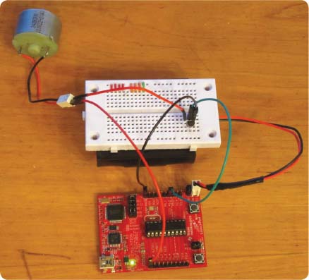
In the photo above, the motor is getting its power directly from the same place the computer is: a pair of C batteries in a battery holder under the solderless breadboard.
The solderless breadboard has a transistor plugged into it. The transistor is acting as a switch. When the center pin of the transistor is brought up to 3 volts by the pin on the microprocessor, it turns the transistor on. The current then can flow through it, connecting the motor to the batteries. When the microprocessor pin is off (at 0 volts, the ground level), then the transistor turns off and the motor stops.
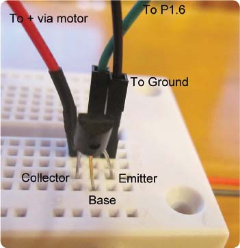
The transistor can be any NPN transistor, such as the 2N2222A transistor shown in the photo above.
You can use pulse width modulation to control the speed of the motor, but this circuit cannot change the direction of the motor.
Only a tiny amount of current is used from the computer pin, so the processor does not heat up. The transistor is controlling all of the current going through the motor, and it can handle a whopping 800 milliamperes. If you need more than that, there are power transistors that can handle many watts of power.
But you can get even more power from the little 2N2222A. You can raise the voltage up to as much as 60 volts. With 60 volts and 800 milliamperes, you can control 48 watts, which is more than most small DC motors can handle.
Here’s how to do it. This example uses a 9-volt battery. The two power supplies (the C cells for the computer and the 9-volt for the motor) will have their grounds connected together. The black wire from the 9-volt battery is plugged into the hole in the solderless breadboard that the emitter of the transistor is plugged into. The blue wire from the ground on the computer is also plugged into a hole that connects to the emitter.
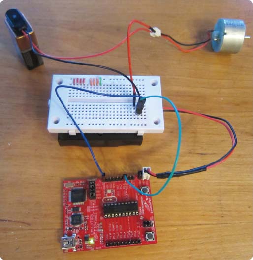
The microprocessor pin is connected to the base, as it was before.
The positive (red) wire from the 9-volt battery is connected to the motor. The other wire from the motor is connected to the collector pin of the transistor.
When the microprocessor turns on the transistor, the current goes from the 9-volt battery into the motor. The battery for the computer is no longer powering the motor. The motor spins much faster, and can actually do some serious work now.
As before, you can control the speed using pulse width modulation.
Connecting the grounds of both power supplies (batteries in this case) gives the computer and the transistor a common reference point, so they both see the 3-volt signal from the computer pin as higher than ground. With the common reference point, they can agree on what an on or off signal is.
An H-Bridge Chip to Control Power
So far you have driven motors forward by connecting them to two pins on the LaunchPad and setting one pin to HIGH and the other to LOW. You have driven them backward by setting the pins to LOW and HIGH.
To get more power, you added a transistor, but you lost the ability to reverse the motor, since the transistor can only connect the motor to one side of the power supply.
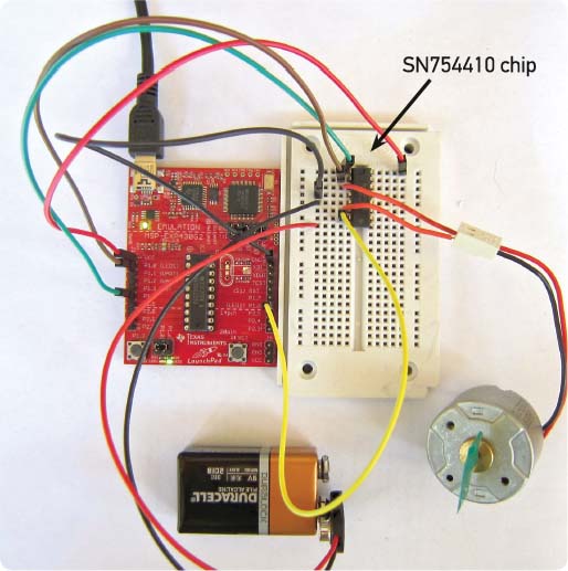
To get more power and still be able to reverse the motor, you need a chip called an H-bridge. It has several transistors in it, and they are all connected in a circuit inside the chip, so interfacing the LaunchPad and motor to it is very simple. The chip is called the SN754410.
In the photo on the previous page, you can see you are only using the left side of the SN754410 chip (pins 1 through 8). The only pin used on the right side is pin 16, which is what powers the input part of the chip. That part of the chip reads the LaunchPad pins, and it is powered by the LaunchPad’s power supply.
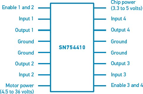
The output part of the chip is powered by a separate power supply (in this case a 9-volt battery). This is what drives the motor. The output side of the chip can handle a power supply with as much as 36 volts, allowing you to drive some pretty powerful motors.
The state of the SN754410’s pin 2 (connected to the LaunchPad’s port 1 pin 0) is “copied” to the SN754410’s pin 3 but at the higher voltage.
Likewise, input pin 7 is copied to output pin 6 but at the higher voltage.
Here is the program (http://artists.sci-toys.com/h_bridge.txt):
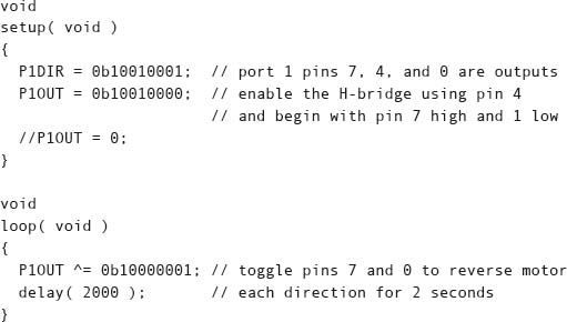
In this project, you are running a single motor, so you only need to use the left side of the chip (pins 1 through 8) and pin 9. I chose to use the LaunchPad’s port 1 pins 0 and 6 to control the motor, since they are connected to the onboard red and green LEDs and you can see which direction the motor is supposed to spin by looking at the lights.
You could have connected pin 1 of the SN754410 to pin 9 so it would always be enabled. But enabling it in software allows you to power down the chip when you aren’t using it and thus save battery power.
If you want to drive another motor, use the other side of the SN754410 chip.
A servomotor is a motor that has gears and a feedback system so that it can change its position, controlled by a pulse width modulation signal.
Unlike the motors you have played with earlier, servomotors typically don’t spin around over and over again. Instead, they move an arm or lever through an arc, generally 180 degrees. You tell the servo how many degrees to move using pulse width modulation.
The servomotor has circuitry inside that contains a transistor to power the motor. This means you don’t need any extra transistor to get more power. You can power the servomotor from a higher-voltage battery, just like you did in the previous section, by connecting the ground (0 volts) sides of the computer power supply and the servo power supply together.
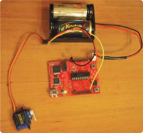
The servomotor has three wires. They are the power, ground, and control wires. In the photo above, the power and ground of the computer are connected to the power and ground wires of the servomotor. The remaining wire—the control wire, also called the signal wire—is connected to pin P2.1 in this example. That pin will be driven by pulse width modulation to control how far the little arm on the servomotor will rotate.
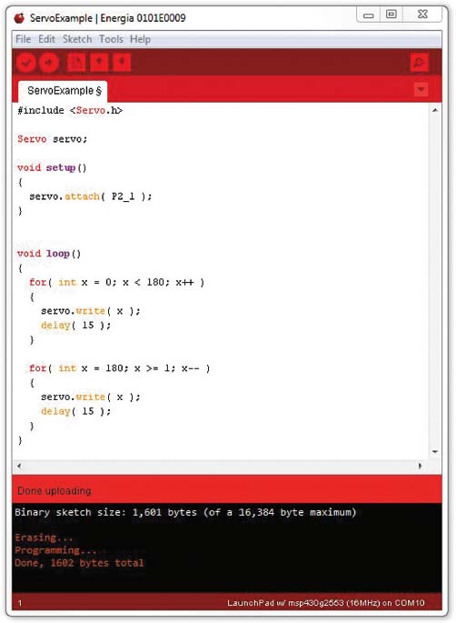
This code for controlling servomotors (http://artists.sci-toys.com/servo _example.txt) uses a class called Servo. It calls the attach method of the servo object to tell it that you are controlling the servo using pin P2.1.
In the loop() function, you have two inner loops. The first one counts up to 180, and the second one counts back down to zero. Inside each loop, the loop counter is sent to the servomotor using the write() method on the servo object. Since the servo takes some time to move, you wait for 15 milliseconds after telling it where to go. If you were moving more than one degree, you would probably want to wait longer. Moving 180 degrees all at once might take 50 to 60 milliseconds.
Servomotors can be surprisingly powerful. Because they have gears, the motor can spin fast, and the gears translate that into slow but powerful motion.
Besides rotary servomotors, you can get linear servomotors, which move things back and forth in straight lines. You can also get much larger, more powerful servomotors and run them from more powerful power supplies, in case you need to move something with more muscle.
A stepper motor is a motor that moves in steps instead of constantly rotating. Stepper motors are used a lot in things like printers, where a computer program needs to move something by an exact amount.
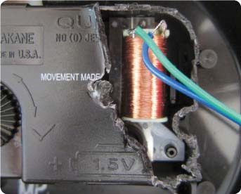
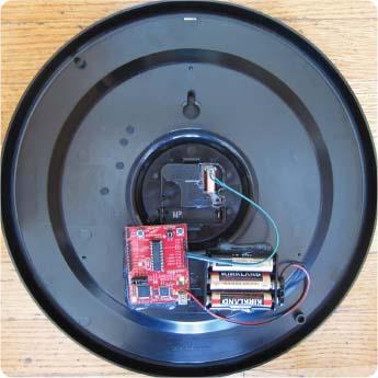
The simplest stepper motor you may have in your house is the little motor that drives a battery-powered quartz clock. It has only one coil (the stepper motors in printers have two), and since it is designed to run from a 1.5-volt AA cell, it is easy to drive it from the LaunchPad instead.
When you drive the clock with your computer, you can make time go as fast or as slowly as you wish. The project described here is one I call Ridgemont High. It drives the clock 50 times faster than normal, to give you “Fast Times.” It runs so fast that sometimes when it starts up, the clock gets confused and runs backward. I can keep pushing the Reset button on the LaunchPad until I see the clock running backward. Sometimes it only takes two or three tries; at other times it takes 10 or more to get it to run backward: www.youtube.com/watch?v=oNTtGTGfa6A.
Building the project is fairly simple. Use a pair of wire cutters to carefully remove part of the plastic back from the clock movement. You don’t want to completely open the back, since the clock gears are very hard to get back into place if you do that. But you can cut open the back until you find the coil of wire that is the heart of the motor, and keep cutting until you find the two wires where the fine motor wire is connected to the rest of the circuit.
Once you find those two wires, solder longer wires to them so you can connect them to port 1 pin 4 and port 1 pin 5 of the LaunchPad.
I like to do all this cutting with the battery in the clock, and the clock running, so I know if I have damaged the clock or not.
Once the wires are soldered in place, remove the battery from the clock and connect the wires to the LaunchPad.
The program for running the clock at any speed (http://artists.sci-toys.com/ridgemont_high.txt) is very simple:
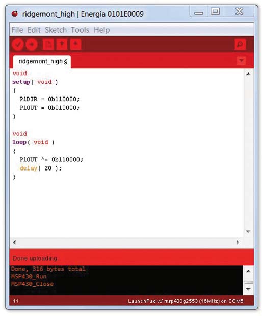
To make the motor turn, first run the current one way through the coil, and then the other. You can do this by setting one pin high and the other low, and then reversing the pattern (so the high pin is now low and the low pin is now high). Each time you reverse the current, the second hand moves by one tick.
The program for running the clock at any speed (http://artists.sci-toys.com /ridgemont_high.txt) is very simple:
Use the exclusive-or operator to flip the bits:

That line says to take any bit in pin 4 or 5 that has the value 1 and set that to 0. At the same time, any bit that was 0 is set to 0.
One of the great things about the little motor in the clock is that it uses very little power. It can run from the AA cell for a year or more. So if you have something you want to make move that does not need a powerful motor, such as a paper sculpture or a faceted crystal you want to place in a sunny window to make rainbows move around the room, you can modify the clock motor to run it and set the speed with the LaunchPad.
That said, when you are running the motor at 50 times its normal speed, it will use more power. To save power when running at normal speed, you could change the program so that the motor was only powered on for 20 milliseconds each second: http://artists.sci-toys.com/ridgemont_high_normal_time.txt. But 20 milliseconds seems to be close to the minimum time needed for this particular motor.
A more elaborate program could change the speed of the motor depending on some change in the environment or simply on the time of day. You could build a clock that ran normally until 9:00 AM, whereupon it would speed up, until lunchtime. Then it would slow down a lot, until the clock read 1:00 PM, when it would race forward again until 5:00 PM. The perfect clock for the clock-watching coworker who wants a long lunch hour.
A More Versatile Stepper Motor
The stepper motors found in consumer appliances like printers and air conditioners generally have four coils instead of just one. One such motor is the 28BYJ-48. It has a motor that makes a full revolution in 64 steps and a set of gears that further reduces the speed (and increases the turning force) by 64.
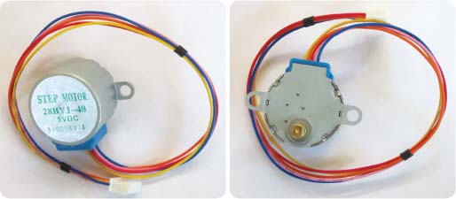
In this motor, the coils are set up in pairs, and the center of each pair is connected to the red wire, which is connected to the positive side of the power supply. The power supply can be anything from 5 to 12 volts.
By connecting any of the other wires to ground, you can energize any of the coils. The coils are electromagnets that pull on little gear-like teeth in the motor. By controlling which coils are pulling at any time, you can make the motor step 1/64 of a circle at a time, either clockwise or counterclockwise. Because of the gearing, you actually step 2,048 times to make the shaft turn one complete turn. This gives you a lot of control over the position of something you are moving.
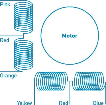
The diagram above shows how the colored wires connect to the coils.
Because the motor moves the same amount each time you step it, you can accurately move back and forth and always land on the same spot.
You do pay a price for the gear reduction in this motor, however. The gears have some play in them, so the shaft of the motor can move back and forth a little bit, causing positioning accuracy to suffer. More expensive stepper motors have more teeth in their rotors and have as many as 200 steps per revolution instead of just 64. These motors generally don’t have gears and can accurately step without any play in the rotor.
Energia has a stepper motor library that takes all of the complexity out of driving stepper motors.
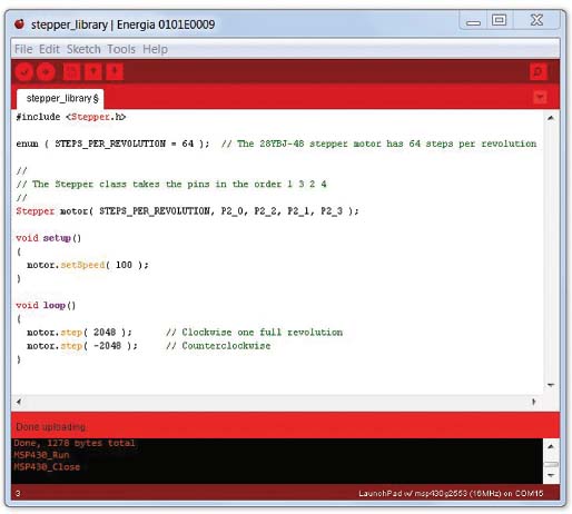
You simply include the header file for the library in your program (http://artists.sci-toys.com/stepper_using_library.txt), and make an instance of the Stepper class (you’ll call your instance “motor”). Then you tell the motor to step some number of steps, using a positive number to step clockwise or a negative number to step counterclockwise.
That’s all there is to it, as far as the software goes.
The problem comes when you realize that the LaunchPad can only put 3.3 volts on a pin and can’t drive the 92 milliamperes needed to make the motor move. You need to add a transistor on each pin. That will both allow you to send a higher voltage to the motor and provide plenty of current to drive the motor.
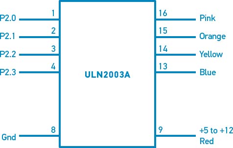
Instead of using four separate transistors, you can use a convenient package of 16 transistors on a chip called the ULN2003A. The transistors are arranged in pairs (called a Darlington pair), which gives them more amplification and allows them to sink more current. You will only use half of the transistors in the chip, since you only have four coils to drive.
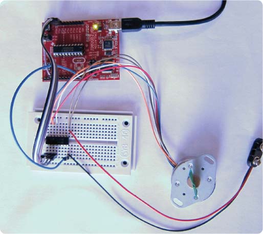
Connect the LaunchPad pins to pins 1 through 4 on the ULN2003A chip. Connect the colored wires on the motor to pins 16, 15, 14, 13, and 9 according to the illustration above. Pin 9 is also connected to the positive side of a power supply that can provide 5 to 12 volts. The negative side of that power supply is connected to pin 8. The LaunchPad’s ground is also connected to pin 8, so the LaunchPad and the other power supply can agree on what 0 volts is.
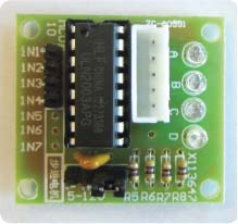
Many suppliers sell the 28BYJ-48 stepper motor and a small circuit board containing the ULN2003A together as a package, making life even that much more convenient. One such circuit board, which also comes with LEDs to show which motor pins are being driven, is shown at left.
However, it is easy enough just to plug the ULN2003A (or, as in the case that follows, the very similar ULN2004A) chip into the solderless breadboard and connect it up. The photo on the next page shows a six-wire stepper motor (a Seiko Epson STP-35N148) being driven by the same demonstration program. It can handle 24 volts (it turns just fine on 4.5 volts, but 24 volts would move heavier loads). The two brown wires are connected to the two center taps of the coil pairs and to the positive power supply (pin 9 of the ULN2004A), just like the red wire in the five-wire motor.
The little LaunchPad computer has three timers that can control three output pins. That means you can tell each of the timers to turn its pin high or low (on or off) at three different frequencies. If you select frequencies in the audible range (16 times per second up to 25,000 times per second) and attach a speaker to the pin, you can make tones humans can hear.
The timers will be simply turning the pin on and off, so the sounds will be the same as those used in early video games, sounding something like a harmonica or a bagpipe.
Because you have three timers, you can play three notes at once. That’s not a lot, compared with what a piano player can do (using 10 fingers and a sustain pedal), but it is enough for many basic chords.
There is a lot of free music available on the Internet in the form of MIDI files. You can search for “free MIDI songs” and find almost anything.
I have written a program that can convert MIDI songs into source code for the three timers in the LaunchPad. If the song is playing more than three notes at once, the program does a fair job of selecting which notes are important to keep and which ones can be shortened or eliminated.
The program is here: http://artists.sci-toys.com/midi_to_launchpad.html.
The LaunchPad has enough memory for most of the songs you will find. If the song is particularly complex or long, the program will convert the entire song but it will comment out the past parts, so the program will still run, even though it cuts the song short.
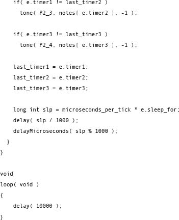
The program you copy and paste into Energia to compile for the LaunchPad is actually fairly simple. It starts with a list of the frequencies for each note. Then there is a list of all the notes to be played. The code that does the playing of the notes is short enough to show here (http://artists.sci-toys.com/music):
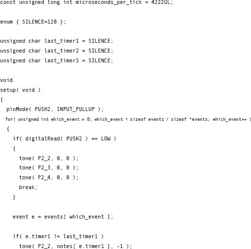
Everything is done in the setup() function. This lets you start the song by pushing the Reset button on the LaunchPad. When the song ends, the LaunchPad goes to sleep until the Reset button is pushed again.
The first thing you do in the setup() function is make the other button on the LaunchPad be an input so you can use it to stop the music. Then you loop through all of the events in the list. An event is a change to one, two, or all three of the notes you can play. If you need to change any note in the song, there is an event telling you what to change.
Inside the loop you check to see if the Stop button has been pushed. If it has, you stop all the timers and break out of the loop.
Otherwise, examine the next event, checking to see which note(s) may have changed. If a note has changed, the program calls the tone() function to tell the timer which pin to use and which note to play. Then you remember which notes are playing (so you can check for a change). Finally, it sleeps for as long as needed until the next event is to be processed.
To hear the music, you need to connect a speaker to the output pins (this program uses pins P2.2, P2.3, and P2.4). Speakers have two wires. One speaker wire will be attached to the ground pin (GND), which is always at 0 volts. The other wire from the speaker goes to one of the three output pins.
If you only have one speaker, you can connect all three output pins together and attach the speaker wire to all three at once. But if you have three speakers, you can space them out so that the listener can hear the notes coming from different places, as if played by different instruments in an orchestra. Many MIDI songs sound like the melody is coming from pin P2.2, the bass from P2.3, and the percussion from P2.4.
You can store a recording of your voice in the little computer to make it say things. The little computer doesn’t have a lot of room for storing audio (it has 16,384 bytes, and the program has to live in that space too), but you can store a few seconds of digitized sound.
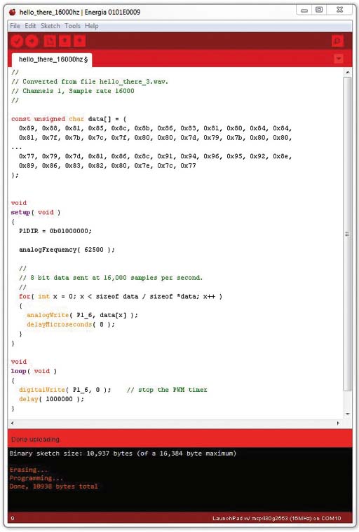
In the program on the next page, I have removed a huge section of code in the middle of the array called “data” to allow the whole program to be seen in a small image. The data is huge because it is almost a second of speech, recorded at 16,000 samples per second. So there are about 10,000 bytes in the array, and it goes on for several pages. The full program is available at http://artists.sci-toys.com/hello_there_16000hz.txt.

STUDENT ART PROJECT
Just Deserts by Patrick Stafford, a desert scene done in handblown neon lights, uses a LaunchPad to play the sound of a pickup truck’s tires rolling over a gravel road when the sonar sensor detects that a visitor has come to view the piece.
I use the keyword “const” in front of the declaration to tell the compiler that this data is not going to change. This allows the compiler to put the data into the same place it puts the code (which, of course, also does not change during program execution). The little computer has 16,384 bytes of flash memory into which programs and data can be placed. It also has 512 bytes of RAM (random access memory) where variables that will change are stored, such as the variable X in the setup() function.
So this program takes up almost all of the space available on the little chip—almost 11,000 bytes out of the 16,384 available.
All of the work is done in the setup() function. Connect a speaker to pin P1.6 and ground. Set P1.6 to output and call the analogFrequency() function to set the PWM frequency to a very high value, in this case 62,500 times per second. The computer runs at 16 million times per second, and you want 256 levels (8 bits worth) for your PWM. Dividing 16 million by 256 gives 62,500.
As an example, suppose the value you want to send is halfway between silence and as loud as you can make the speaker go. Your PWM would then turn the P1.6 bit on for 128 cycles of the 16 megahertz computer clock and then off for another 128 clock ticks. You can do 62,500 of those every second.
You have recorded the sound at a rate of 16,000 samples per second. In the “for” loop in setup(), you go through the entire data array, calling analogWrite() to set up the PWM to the value in the array. To ensure that you send the samples at the 16,000 sample-per-second rate (so you don’t sound like you are breathing helium), you delay for eight microseconds after each data byte is sent. In this way, almost four PWM cycles happen for each data byte (62,500 divided by 16,000 is about 3.9).
The loop() function just sleeps, to save battery power if you are running off batteries. But first you have to turn off the PWM timer, which would otherwise keep sending pulses to P1.6. You do that by using the digitalWrite() function, which has the side effect of turning off the analogWrite() timer. If you didn’t do this, the speaker would waste battery power trying to stay in some position other than at rest.
To hear my voice, just press the Reset button on the LaunchPad. Every time the LaunchPad gets power or resets, the setup() function gets called and it sends out the data.
At this point you might be wondering where all that data came from. I recorded my voice saying “Hello there!” on my laptop computer. I told the recording software to save the recording as a .WAV file, using 8-bit samples at 16,000 samples per second. Then I uploaded the .WAV file into a program I wrote that converts the sound into C++ source code. I then used copy and paste to copy the code from the web browser to the Energia program to compile and run.
You can find the program to convert speech recordings into LaunchPad code here: http://artists.sci-toys.com/wave_to_launchpad.html.
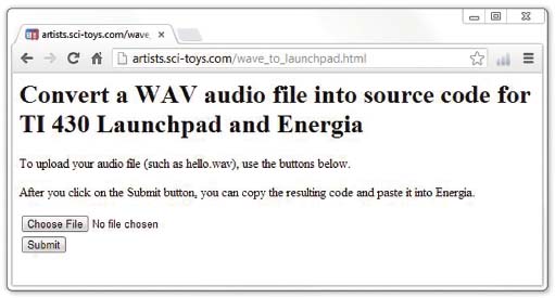
The program is very simple to use. Click on the Choose File button to select the .WAV file you want to upload from your computer. Then click on the Submit button. A new window will pop up with the source code for you to copy.
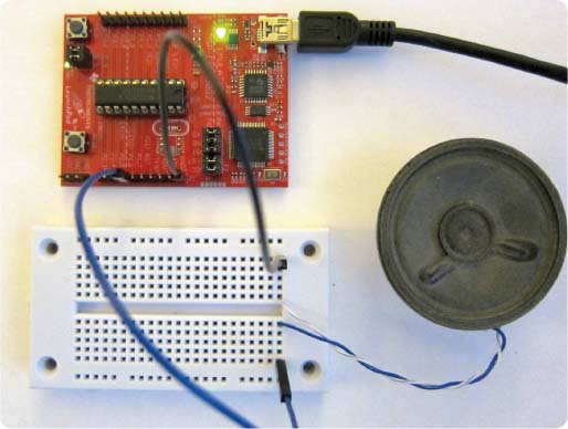
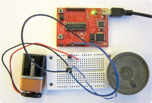
The connections are simple and are shown in the image above.
The little LaunchPad computer can’t drive the speaker as well as you might like. The sound coming from it might be hard to hear in a noisy room. But you can fairly easily amplify it using a single NPN transistor, such as the 2N2222A, or the 2N4401, or even the big TIP31 power transistor.
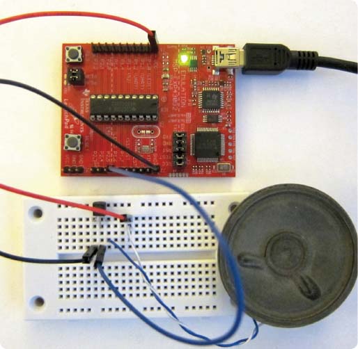
You connect the P1.6 pin to the base lead of the transistor (the middle lead in this example). Connect the ground to the emitter lead (the leftmost lead). Connect the speaker to the collector (the rightmost lead), and the other speaker lead connects to the +3.3-volt power supply of the LaunchPad (marked VCC on the board).
Below is a close-up of the transistor part of the circuit:
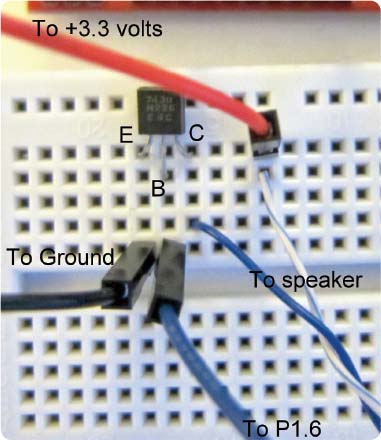
Now the sound comes out reasonably loud. But you can make it even louder by using a second power supply, just for the amplifier. Here is how to use a 9-volt battery:
Remove the connection to the +3.3 volts on the LaunchPad board. Keep the connection to ground, so the amplifier and the LaunchPad both agree on what 0 volts is.
Connect the negative side of the 9-volt battery to ground. The positive side goes to the speaker, in place of the wire that used to go to the +3.3 volts on the LaunchPad.
Now when pin P1.6 turns on the transistor switch, the 9-volt battery current goes through the speaker, instead of the previous 3.3 volts.
The result is substantially louder.