The LaunchPad can communicate with people, other computers (such as a laptop), other LaunchPads, or devices such as televisions and table lamps.
You have used LEDs and speakers to communicate with people. Sometimes DC motors, servomotors, or stepper motors are used to communicate with people by moving signs or waving robot arms. An art piece such as a sculpture or jewelry could communicate with the viewer or wearer, and interact with him or her.
Communicating with a larger host computer allows the LaunchPad to interact with the Internet or with a person typing on a keyboard. Artists could thus control an art piece using the mouse and keyboard on their laptop computer and send the LaunchPad signals to control the piece. Or the laptop could send the host computer data such as the number of visitors it has interacted with, or the state of its batteries, or some error condition if the piece is damaged.
You have already played with using the Serial class to send information such as temperature or debugging messages to the host computer. You have also seen how to use the Serial class to control the brightness of 14 LEDs at once (http://artists.sci-toys.com/serial_pwm.txt) by sending short commands from the host computer.
Some projects might require more resources (pins, timers, or computational power) than a single LaunchPad can deliver. Connecting two or more LaunchPads together in a network allows you to have more resources to devote to the project.
The LaunchPad is also able to control other devices and appliances. You have seen how you can control 120-volt power to lamps and motors, but you can also send infrared signals to anything that uses an infrared remote control, such as a television, audio device, camera, or even parts scavenged from a toy helicopter. Infrared remote controls use infrared LEDs to send the signal, and you are already adept at controlling LEDs.
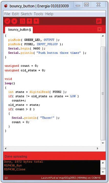
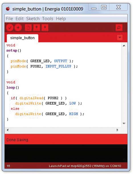
For the most part, using the button on the LaunchPad is pretty easy:
You run the code (http://artists.sci-toys.com/simple_button.txt), press the button, and the light comes on. You run into problems immediately, however, if you try to count the button pushes:
The program on the previous page does not work properly. You will find that the program sometimes prints “Three!” after only one or two button presses.
This is because mechanical buttons bounce when you push them. Each push connects the contacts in the button, but then the contacts bounce away and disconnect before connecting again, often several times. The LaunchPad is so fast that it can ask the state of the switch many times during this bouncing period and get different answers as to whether the contacts are closed or not.
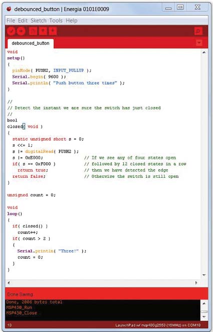
You need to add code to “debounce” the switch. This is not quite as simple as waiting until the bouncing has stopped. You must make sure that you wait less than 50 milliseconds so that the response to the switch still seems instantaneous to a human, and you want to avoid triggering on electrical noise generated by static electricity or nearby motors causing spikes in voltage.
One way to do this is to examine the switch multiple times and look for a pattern that has any number of “true” states (the switch was closed when you looked) followed by 12 states in a row where the switch was definitely closed. You can do that by using some tricky bit-twiddling code in the function closed() in the program (http://artists.sci-toys.com/debounced_button.txt) shown on the next page.
You have a variable called s that is static—that is, it retains the information in it across function calls. It can hold 16 states, one per bit.
Shift the variable left so each new state is added as the lowest bit.
Then you “or” in the value 0xE000. This makes the top three bits always be 1 bits. That will mean that you don’t care whether they were on or off in the comparison on the next line.
The next line asks if the value in s is exactly 0xF000—or, in other words, any number of 1 bits followed by exactly 12 0 bits. If this is true, then you have detected when the switch has stopped bouncing and has been fully closed for 12 samples.
The next time you call closed() it will return false, because you are no longer at the precise point when the switch was closed. It may be closed or still open; you don’t care.
Note that you have to check closed() multiple times before you get a true. This is usually done in a loop (as you did here) or in a timer routine. You can call closed() every four milliseconds and still be inside the 50-millisecond response window.
Walk through the code in your head until you are sure you understand it. It is a bit tricky but very useful.
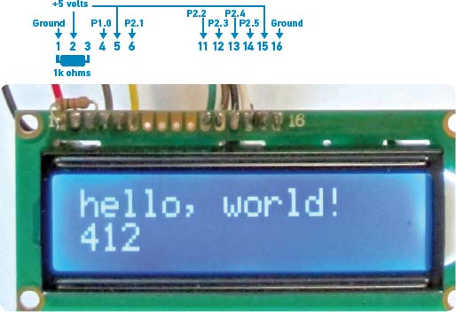
Up to this point, you have done communication between the LaunchPad and the human user using blinking LEDs, sounds, and the serial monitor. In this project, the inexpensive 2-line-by-16-character LCD display is introduced.
These displays allow you to communicate text messages to the user without requiring another computer to display them.
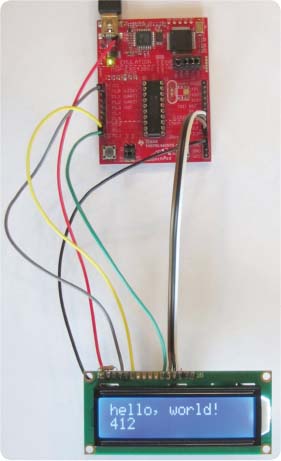
The photo above shows such a display. This one has white letters on a blue background, lit by an internal white LED backlight.
The display is powered by 5 volts, so you need to get the power from the TP1 test point on the LaunchPad, as you did when you used the sonar sensor. Pin 1 on the LCD display is ground, and pin 2 is 5 volts. The third pin controls the contrast of the display. I find that a simple 1k-ohm resistor between this pin and ground gives nice contrast on the display. To make the contrast adjustable, you can connect a potentiometer between ground and 5 volts and connect the wiper terminal of the potentiometer to pin 3. I find it usually is not necessary.
Pins 15 and 16 are connected to 5 volts and ground to light the LED backlight. You can add a resistor between pin 15 and 5 volts to dim the LED and save some battery power if you like.
Pin 4 on the LCD display is the Register Select. When low, data coming in is interpreted as a command. When high, data coming in is interpreted as text to display. Connect this pin to the LaunchPad’s P1.0 pin.
Pin 6 is the Clock Enable pin. Connect that to the LaunchPad’s P2.1 pin.
The data pins are 11 through 14. Connect these to the LaunchPad’s P2.2, P2.3, P2.4, and P2.5 pins.
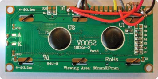
The bottom view of the board shows that pins 16 and 1 have been connected with a jumper, and pins 15, 5, and 2 with two more jumpers.
The LaunchPad and display can be seen connected together in the following photo:
The Energia software comes with a library that makes sending text to the LCD display very simple (http://artists.sci-toys.com/minimal_lcd.txt). Printing the words “Hi there!” is as easy as this:
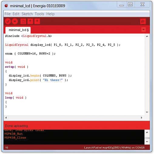
The library contains code that lets you select the row and column where you wish to print, code for clearing the screen, and other simple functions. It also has an “autoscroll” function that turns on a feature in the module that is supposed to make it easy to send characters that scroll off the screen when new characters come in. However, it seems to behave in strange ways, jumping from one row to the other at strange times. But since writing code to scroll properly is not difficult and takes up little space in the LaunchPad, I just wrote my own code when I wanted a program to receive serial data from other devices and display it on the LCD panel (http://artists.sci-toys.com/lcd_serial.txt).
When you load that program onto the LaunchPad, whatever you type in the top line of the serial monitor gets displayed on the LCD screen. To actually see it handling special characters like carriage return, line feed, and backspace, you will want something a little better than the serial monitor, such as HyperTerminal, PuTTY, or some other terminal-emulation program running on your computer.
The LaunchPad comes with an extra MSP430 chip, the MSP430G2452. In this project you will get to play with it again, since you want to extend the capabilities of your LaunchPad to control more LEDs.
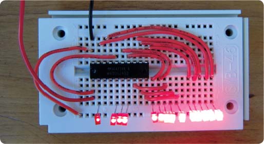
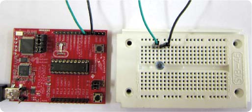
First you will build the 14-pin PWM circuit from the Serial PWM section (page 88). You do it on a solderless breadboard as shown in the photo below:
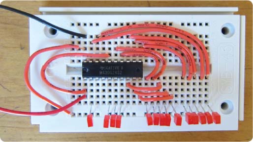
In this photo, the extra chip is mounted on the breadboard. Connect the Reset pin to the +3 volts of the power supply so the chip does not constantly reset itself.
When you apply 3 volts, the LEDs light up, getting successively brighter from left to right.
Notice that you have not connected anything to pins P1.1 and P1.2 yet. Those are the serial port pins. Since this chip is not mounted in the LaunchPad board, you can’t send serial data to it from the host computer, as you have done in the past. But you can connect the serial port pins of the chip in the LaunchPad to the serial port pins of the chip on the breadboard, and they can talk to one another.
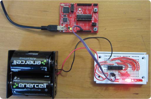
In the photo at the bottom of the previous page, you can see the LaunchPad connected to the breadboard circuit. P1.1 of each chip is connected to the other, as is P1.2.
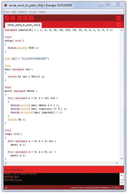
The program (http://artists.sci-toys.com/send_to_serial_pwm.txt) running in the LaunchPad is shown on the previous page. It tells the chip on the solderless breadboard to set the LED brightnesses to get gradually larger and then smaller again. Then it makes the peak brightness move back and forth along the 14 LEDs, as if it were the scanning sensors on a Cylon robot, or KITT the Trans Am on Knight Rider.
To program the extra chip (the MSP430G2452), first carefully remove the MSP430G2553 chip from the LaunchPad. The chip is sensitive to static electricity, so you want to touch something that is grounded to get rid of any charge on your hands before touching the pins. Then place the chip on something conductive, such as a sheet of aluminum foil, to protect it from static electricity. Wearing cotton or wool clothing instead of nylon or polyester will also help reduce static electricity.
The pins on the extra chip may need to be straightened before they will fit into the socket. Many chips come from the factory with the pins splayed out just a little bit.
Once the new chip is inserted into the socket, you will need to remember to change the Tools/Board menu to let Energia know you are using the MSP430G2452 chip instead of the MSP430G2553 chip that was originally in the socket.
Note: If you want to test the chip by sending serial data to it, you will also need to change the TXD and RXD jumpers on the LaunchPad from the hardware UART setting to the software UART setting, since the extra chip does not have a hardware UART (universal asynchronous receiver/transmitter—i.e., serial port). But that step is not necessary if you aren’t testing the new program from the host computer.
The next step is to program the chip with the Serial PWM code: http://artists .sci-toys.com/serial_pwm.txt.
Then disconnect the power, remove the chip from the LaunchPad, and place it in the solderless breadboard.
Now put the original MSP430G2553 chip into the LaunchPad, set the Tools/Board menu back to MSP430G2553, and load the program to send serial data (http://artists.sci-toys.com/send_to_serial_pwm.txt) to the chip in the breadboard.
When you connect the two chips’ serial pins together and power everything up, you get a scanning LED pattern moving on the breadboard. The chip in the LaunchPad has outsourced the work of doing the pulse width modulation to the chip in the breadboard. Now the LaunchPad is free to spend its time doing other things, and it has 14 pins free to use for inputs and outputs.
You can connect several of the circuits together using four wires (power, ground, serial in, and serial out) as shown in the following photo:
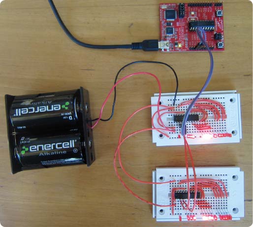
Both of the solderless breadboards are lighting their LEDs in sync, controlled by the LaunchPad.
Controlling the extra chips this way means that you can change what all of the “slave” chips do just by changing the one program in the LaunchPad. You don’t have to keep unplugging and plugging in chips when you want to make a change.
You can take things one step further and make it so you can control 16 of the extra chips individually. To do this, give each one an address. This is just an extra digit in the sequence you send to the chip. Each chip is programmed with a number from 0 to 15, which is its address. You send the address as the first character of the sequence. If the chip sees that the address it not its own, it simply ignores the command sequence.
The program for the slave chip is here: http://artists.sci-toys.com/addressable _serial_pwm.txt.
The program for the master chip is here: http://artists.sci-toys.com/addressable _send_to_serial_pwm.txt.
As the photo below shows, now the two slave chips are not merely mimicking one another in lockstep. You have turned your 14-LED Cylon into a 28-LED Cylon.
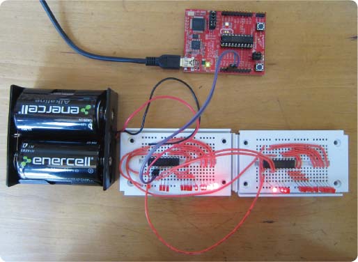
With 16 slave chips controlling 14 LEDs each, one master LaunchPad can control the brightness of as many as 224 individual LEDs. And if you need more, you can just add another digit of address, to control 3,584 LEDs.
Having lots of PWM pins comes in very handy when you want to control the color of a lot of RGB LEDs. Each RGB LED has a red, a green, and a blue LED inside the plastic lens, so it has four leads. It thus takes three pins to control the color (and brightness). One chip can control only four or five of these LEDs at a time before running out of pins. But with a slave chip, you have 28 pins available, so you can control 9 RGB LEDs and still have one pin left over.
You may have noticed that you are only using two wires (transmit and receive) to communicate between the various computers. How can they agree on what 0 volts means if they do not share a common ground connection? As it turns out, for short connections like this, the computers agree on a common ground whenever the lines are in the LOW state. For longer wires, the capacitance of the wire would delay this agreement by enough to cause problems, and you would need to connect the grounds of the computers with another wire. But for short connections, this works.
The serial port and the Serial class that manages it deal with asynchronous communication. This just means that there is no shared clock in the two computers. Each computer has its own clock, and each expects the bits to have an agreed-upon duration. This means the computers need to agree on how fast the bits are sent. If one computer is sending data at 9,600 bits per second, and the other is expecting them to come in at 1,200 bits per second, they will not be able to communicate.
Synchronous communication uses another wire to send pulses that act as a clock. This means that the two computers no longer need to agree ahead of time on the speed of the communication, and thus the duration of the bits. The clock pulses tell the receiver when to look at the state of the pin receiving the bits.
The LaunchPad has hardware that makes it easy to use a form of synchronous communication called SPI, which is short for Serial Peripheral Interface. This method is used by many devices that need to communicate with the microprocessor, such as temperature sensors, barometric sensors, digital potentiometers (volume controls), radio interfaces, switches, and other input or output devices.
In the previous example of a serially controlled pulse width modulator for LEDs, each slave device was programmed with its own address and you sent the address as part of the serial data. SPI uses another wire to do the addressing. Each SPI slave device has a pin it can read to see if it has been addressed. The host SPI device sets a pin high to tell the slave it should listen to the data. In this way the host can communicate to as many slaves as there are spare pins to address them. And each slave can run the same software, since they don’t need to be programmed with their own address.
So the SPI interface has four wires between the two devices. There is the clock (called SCLK); the master out slave in (MOSI), which is how the master talks to the slave; the master in slave out (MISO), which is how the slave talks to the master; and the slave select (SS) line, which tells the slave to listen.
Each slave shares the first three lines. Only one slave at a time is selected.
On the LaunchPad, SCLK is always pin P1.5, MOSI is always pin P1.7, and MISO is always pin P1.6. You get to choose which pin you use for the chip select (CS) function.
One big advantage you get from using a synchronous protocol is speed. Few asynchronous devices can reach a million bits per second, and the LaunchPad serial is limited to 9,600 bits per second when talking to the host computer. But the SPI clock can run at 8 million bits per second.
You don’t always need that speed, so you use ordinary serial communications more often, as they use fewer pins. But fast communication comes in handy when you want to read external memory, such as the SDHC cards used in digital cameras. These cards can talk to the LaunchPad using SPI.
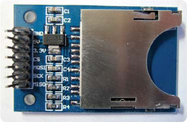
The photo above shows an SDHC card reader. The card slips into the large metal socket on the right. On the left you can see seven pairs of pins. You will only use six pins, since the card reader can run on either 5 volts or 3.3 volts and you only need the 3.3-volt pin. The second row of pins is not needed.
As you can see in that photo, the pins are labeled GND (ground), 5V, 3.3V, CS (Chip Select), MOSI, SCK, and MISO. All you need to do is connect those pins to their counterparts on the LaunchPad:
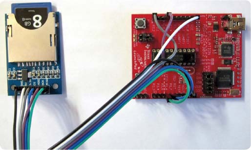
In this project, you will connect the pins using a six-strand ribbon cable with female sockets at each end. Follow the wires in the photo on the previous page to see how each labeled pin on the card reader is matched to the appropriate pin on the LaunchPad.
Dealing with all the complexities of reading files on the SDHC card is made easier by a library of routines you can load onto the LaunchPad. The version of this library that I used is in the file pfatfs.zip, and you can download it if you like, but the latest version can be found here: http://forum.43oh.com /topic/3209-energia-library-petit-fatfs-sd-card-library/, along with support from the people who wrote it.
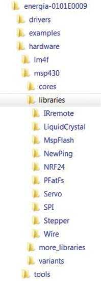
When you installed Energia, a tree of folders was created on your computer. On my computer, the tree looks like the image at left.
To install the pfatfs library, you want to unzip the file into the energia/hardware/msp430 /libraries folder. It will then sit among your other libraries such as Servo and Stepper, and you can use it the same way you use them. On your machine, the Energia directory is named whatever you called it when you installed Energia. If you have forgotten where it is, search your computer for Servo or Stepper and you will find it.
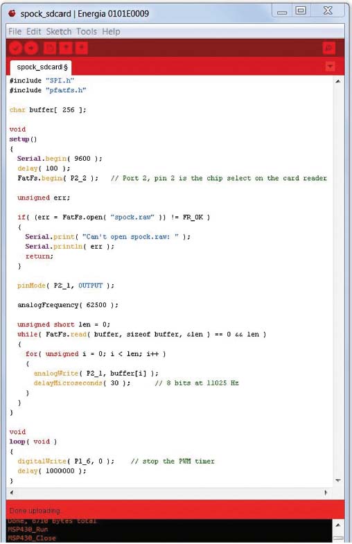
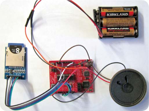
The program on the next page (http://artists.sci-toys.com/spock.txt) reads a file from the SD card and sends the data to a speaker using analogWrite():
The first things you do are include the header files for the SPI and pfatfs libraries. The parts of the program that deal with the SD card are the FatFs class methods begin(), open(), and read().
Tell the begin() method which pin you have chosen to use as the Chip Select signal. Tell the open() method the name of the file you wish to open. Tell the read() method where to put the data, how much to read, and the address of a variable that will return how much was actually read (you may be near the end of the file).
That’s how simple it is.
Almost.
There are some limitations on what you can do with the SD card. To keep the library small enough to fit on the LaunchPad, some limitations were introduced. File names cannot be longer than eight characters. You can overwrite bytes in a file, but you cannot create new files or make files longer.
To finish up this project, put a file on the SD card. The file I chose is a raw sound file, consisting of just a sequence of unsigned bytes. Most sound editing programs have the ability to output the sounds in raw format. In this case, the file is Leonard Nimoy’s voice as science officer Spock, recording a message on his answering machine. The MP3 version of the file you can actually listen to right now is here: http://artists.sci-toys.com/nimoy_spock.mp3. The raw version to put on the SD card is here: http://artists.sci-toys.com/spock.raw. Right mouse on that last link and select Save As to download the file onto your computer.
To hear the message from Spock, you need a speaker. Below, I have chosen to amplify the speaker using a TIP31 transistor.
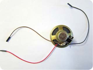
The left leg of the transistor is the base. It will be connected to pin P2.1 on the LaunchPad. The center pin is the collector. It is soldered to one of the speaker leads. The right pin is the emitter. It connects to ground on the LaunchPad. Finally, connect the other speaker lead to VCC (3.3 volts) on the LaunchPad. Using a transistor gets you plenty of volume out of the speaker.
Last, to make it portable, I soldered pins to the TP1 and TP3 holes next to the USB cable, so I can plug in a battery pack to yield nearly 5 volts.
Now every time you push the Reset button or power up the LaunchPad, you hear Spock’s answering machine message.
You are no longer limited by the small amount of flash memory on the LaunchPad when it comes to storing voice data. Where before you were limited to a little more than a second of sound, now you can store days and days’ worth.
Using Bluetooth wireless communications with the LaunchPad is made easy by the HC-07 Bluetooth-to-Serial board. It is inexpensive (usually less than the LaunchPad costs) and will free you from needing a USB connection unless you are reprogramming the LaunchPad’s chip. With the HC-07 board, you can talk to the LaunchPad wirelessly, from across the room or even farther.
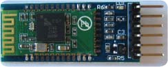
The HC-07 board is a little thing, smaller than my smallest finger. It has six pins, but you will only be using the four inside pins.
The pins are power (VCC), ground (GND), serial transmit (TXD), and serial receive (RXD). The board can run on anything from 3.3 volts to 6 volts, so you will use the LaunchPad’s VCC, which is 3.3 volts.
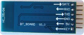
Connect the LaunchPad’s port 1 pin 1 to the HC-07’s TXD pin, and the LaunchPad’s port 1 pin 2 to the HC-07’s TXD pin. Connect power and ground and the hardware is ready to use. It’s that simple.
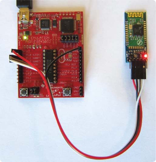
The board defaults to 9600 bits per second (baud), just like the LaunchPad does, so there is no configuration needed. You will run at faster speeds later, but for now, leave it in the default mode.
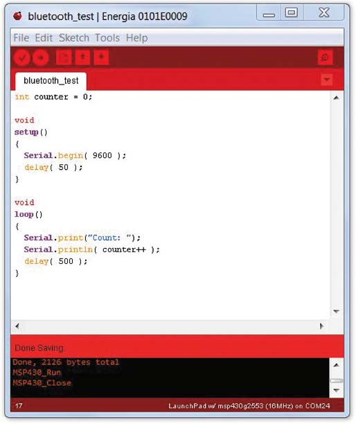
Start with a very simple program (http://artists.sci-toys.com/bluetooth_test .txt) that simply prints a count to the serial port:
Now all you need to do is to connect to the Bluetooth device using your computer, cell phone, or tablet.
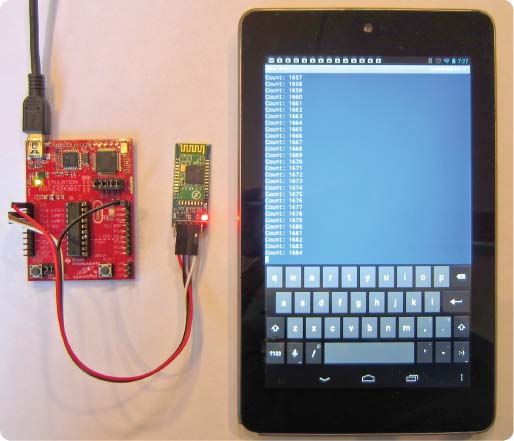
The photo above shows the LaunchPad talking to a Nexus 7 tablet (an Android device made by Google). The program it is running is BlueTerm, a free terminal program that lets you send and receive characters over Bluetooth as if you were connected by wires.
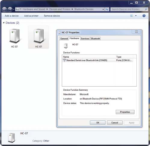
On my Windows laptop computer, I simply connect to the HC-07 using the Bluetooth Devices page and then use a terminal program such as PuTTY to connect to the COM port associated with the Bluetooth device I have connected to. In this case, it is COM25.
When connecting to the HC-07, the user is prompted for a PIN number. The default for the HC-07 is simply 1234.
Now that you know how to talk to the LaunchPad using Bluetooth, you can control your sculpture, robot, or work of art from your cell phone.
You communicate with many of your devices in the home using infrared light. Your television remote control sends pulses of invisible infrared light to the television to change channels. Many toys have infrared remote controls. The LaunchPad computer can send and receive these signals, with the addition of an inexpensive infrared LED and infrared receiver.
My friend Ken Shirriff has written a library for the Arduino that takes most of the work out of decoding the signals. This library also works on the LaunchPad and comes included with Energia. There are several examples in the File/ Examples menu.
There are millions of ways to encode data onto a stream of pulses of light. Due to patents, trade secrets, and other competitive barriers to standardization, there are hundreds of schemes currently in use. The infrared library included with Energia supports six common schemes—NEC, Sony, RC5, RC6, Dish, and Sharp. So if you own a universal remote control, you can set it to one of those and the LaunchPad can receive its signals.
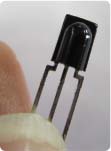
To receive the signals, you want an infrared receiver module.
This is a three-terminal device (power, ground, and output). They come in different frequencies, but the most common is 38,000 hertz. Most remotes use 38,000 hertz. Those that use nearby frequencies (31,000 hertz, 36,000 hertz, etc.) will work with a 38,000-hertz receiver module, but the range will be smaller.
Connecting the receiver module to the LaunchPad is simple:
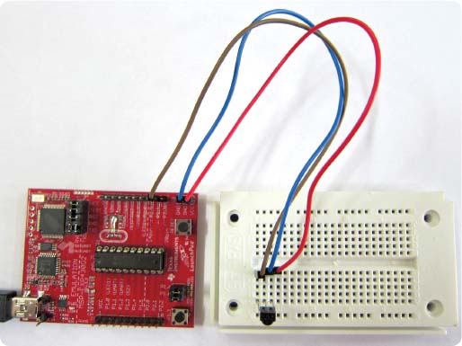
Power and ground are obvious, and the output (connected to P2.5) can be connected to any LaunchPad input pin.
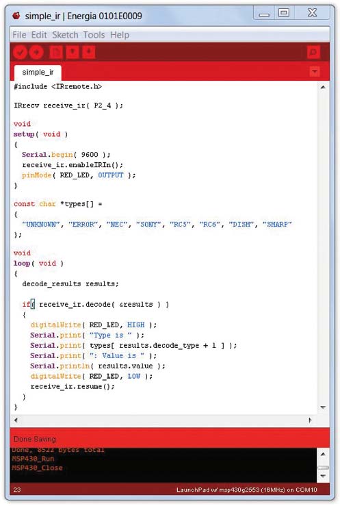
The program to read the infrared signals (http://artists.sci-toys.com/simple _ir.txt) and send the results to the serial monitor is fairly simple.
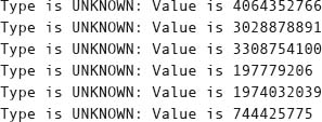
When you press a button on the remote, the serial monitor shows something like this:
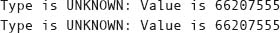
The type is listed as UNKNOWN because I was using a DirecTV remote, which uses a different protocol than those the library knows about. Two values are shown because most remotes send the code more than once for each button press, to make sure the message gets through. Sometimes a special code is used for “repeat.” For the purposes here, you can ignore that special code.

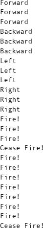
Suppose you want to use the remote to control a robot. The remote has some buttons that form a little circle, and you can interpret those buttons as forward, backward, left, and right, and the middle button can be beep, or fire, or whatever you like. If you push the buttons in that order, you see:
The center button, marked SELECT, sends one code multiple times while the button is held down, then another code when the button is up. You will interpret that as Fire! and Cease Fire! respectively.
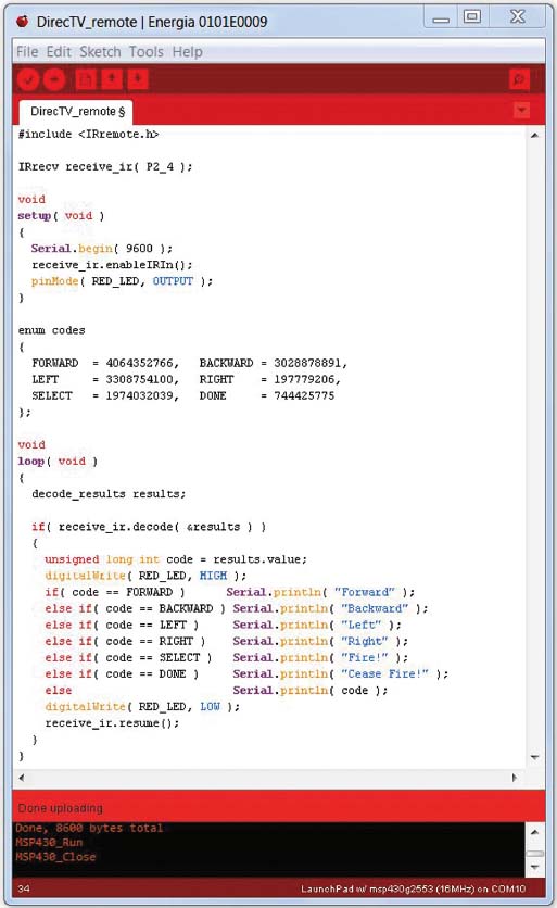
Now you can write a new program (http://artists.sci-toys.com/directv _remote.txt) that shows you the commands that you would use to control the robot.
Pressing the keys on the remote now shows you:
Sending infrared codes from the LaunchPad to some other device is also fairly simple, thanks to the infrared library. You will need an infrared LED to send the signals.
You can use the infrared LED the same way you use a visible-light LED. However, it is not possible to tell whether it is working just by looking at it, because you can’t see infrared light. But you can use a trick. You can aim a camera (such as the one in your phone) at the infrared LED and watch the flashes on the camera’s screen, since the digital sensor in the camera is sensitive to infrared.
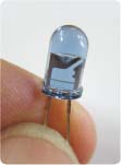
Connect the LED to P2.3 and ground. The long lead is the cathode (which connects to ground). The short lead is the anode, and it connects to P2.3.
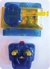
You are now going to use the infrared LED to control a small toy tank.
You can use the previous program to see what the signals from the tank’s remote look like. Unfortunately, they are not sent using one of the coding methods known by the library. However, you can extend the library so that you can control the tank.
The library collects the bits that the remote sends to the LaunchPad. You can print out those “raw” numbers, which tell you how long the LED was on and how long it was off, for each of the flashes the remote makes as it sends the code. By looking at those numbers, I found that the tank’s remote started each command with a flash that lasted 1.772 seconds. Then there was a dark period of 0.34 seconds. That sequence marked what is called the header.
To send a 1-bit, the tank flashes the LED for 0.36 seconds, followed by a dark period of 0.82 seconds.
To send a 0-bit, the dark period is only 0.34 seconds.
There are five bits sent for each command. That allows 32 different commands to be sent.
Using this information, you can now extend the library’s IRsend() class. You will call your class “tank” and grant it all of the functions of the IRsend class by telling Energia that your “tank” class inherits from IRsend. The line that does that looks like this:

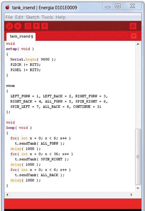
Now here’s what the code for the new “tank” class (http://artists.sci-toys.com /tank_irsend.txt) looks like:
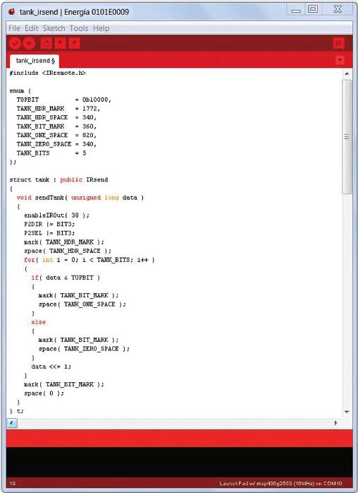
You have created a new method, called sendTank(), that will flash the infrared LED in just the right sequence to send your commands to the tank. Now you can look at the rest of the program as it uses the new class to send commands to the tank:
You send the tank forward, then spin it right for a while, and then make it move backward.
Sending the number 0b00001 (that’s just the number 1) to the tank moves its left tread forward. Sending a 0b0010 to it (the number 2) moves the left tread backward. Sending a 5 moves both treads forward, and so on.