Follow the breadboard diagram shown next to build the distance measurement device. The diagram shown on the next page is quite complex. Take your time as you unravel through it. All the components (including the Arduino board) in this prototype are powered from the 9 volt battery.
It is very important to note that unless the header pins are soldered properly into the LCD board, the LCD screen will not work correctly.
This is a very challenging prototype to get working in one go. Make sure there are no loose jumper wires.
Notice how the positive and negative terminals of the power source are plugged into the VIN and GND pins of the Arduino board respectively.
The 10K potentiometer has three legs. If you look straight at the breadboard diagram, the left hand side leg of the potentiometer is connected to the 5V power supply rail of the breadboard. Some typical potentiometers that can be used in this chapter are shown as follows for reference:

The right hand-side leg is connected to the common ground rail of the breadboard. The leg in the middle is the regulated (via the potentiometer's 10K resistance dial) output that controls the LCD's V0/VEE pin. Basically, this pin controls the contrast of the display. You will also have to adjust (a simple screw driver may be used) the 10K potentiometer dial (to around halfway at 5K) to make the characters visible on the LCD screen. Initially, you may not see anything on the LCD, until the potentiometer is adjusted properly.
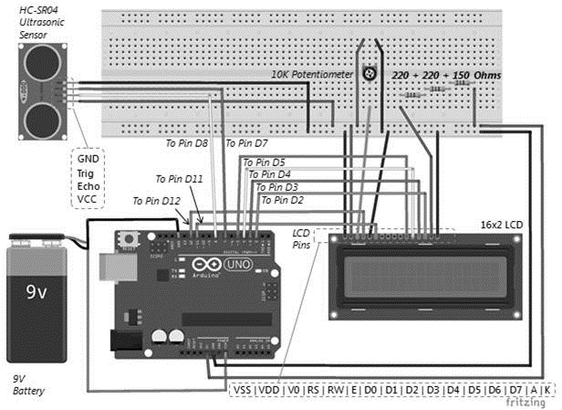
When the 'Trig' pin receives a signal (via pin D8 in this example) this results it sending out ultrasonic waves to the surroundings. As soon as the ultrasonic waves collide with an obstacle, they get reflected. The reflected ultrasonic waves are received by the HC-SR04 sensor. The Echo pin is used to read the output of the ultrasonic sensor (via pin D7 in this example). The output read from the 'Echo' pin is processed by the Arduino sketch to calculate the distance.
The 16x2 LCD to Arduino Uno connections are tabulated next. Concise descriptions of the important pins are also provided here for easy understanding. For a detailed description, you may refer to the 16x2 LCD datasheet available online:

The HC-SR04 ultrasonic sensor to Arduino Uno connections are tabulated next:
|
HC-SR04 Sensor pin |
Arduino Uno pin |
|
VCC |
5V |
|
Trig |
Digital I/O Pin 8 |
|
Echo |
Digital I/O Pin 7 |
|
GND |
GND |
The power source to Arduino Uno connections are tabulated next:
|
Power source (9V) |
Arduino Uno pin |
|
Positive terminal |
VIN |
|
Negative terminal |
GND |