Ray Fleck
As I get old and my carcass slowly falls apart, I seek out accommodations for hitting the target. Easy “assists” are better sights, better grips and a better trigger. I acquired this SIG P220 when I could still see — a long time ago — and put the Hogue grips on promptly. A few years ago I upgraded the sights to “LPA Sights” and this was a step up from the glow in the dark sights the gun came with. Now my groups are opening up — again. The next assist for old eyes is a red dot sight. I have the slide-mounted sort of red dot on other guns, but I wanted to test the bridge mount idea.
Being frugal, and not liking aspects of the bridge mounts on the market, I decided I would just build one.
The target with holes made by Black Hills HoneyBadger ammo is testimony the mount and sight are a good shooter assist. At 25 yards with the LPS iron sights the group would have been 2–3 times as big. The all-copper alloy bullet (135 gr.) in HoneyBadger has good terminal performance with less recoil than a traditional 230-gr. .45 bullet. Less recoil is demonstrated by less vertical stringing compared to the SIG 230-gr. ammo. The SIG ammo is great ammo, and so is the red dot sight I use from them, but a lighter bullet may help you to shoot better, so give it a try.
My first thought on the vertical stringing was something was loose in the mount. Lots of ammo later I was confident the only loose screws were mine. My wrist, arm and shoulder no longer like recoil and it shows up as vertical stringing. Inconsistent grip/control will cause vertical strings too.
The design of my home-made mount works well, and it points naturally even though it’s higher above the bore than a slide-mounted red dot. The only modification to make would be to move the sight a bit forward if you make one. It’s too close to the ejection port and the back of the sight collects splattered lube. Let’s show you how I did it with a step-by-step look.

The basic parts set out to assist visualizing how the result might look. Ray also used this method to take starting measurements as to how the sight and gun had to work together. The sight needs to be as low to the slide as possible and the front sight should not whack the red dot sight while cycling.

While observing the finished contraption, a friend of Ray’s (another engineer) commented it was a neat and simple solution. He is mostly correct; but even a simple project like this will cause less angst if you do the math and make drawings before you start. This drawing is two times life size. The effort to make this drawing to scale saved Ray from making any parts over.

The repurposed Picatinny mount came with the ROMEO5 sight. The green taping goop makes for less broken taps. Ray didn’t have access to his milling machine so he did this build the hard way!
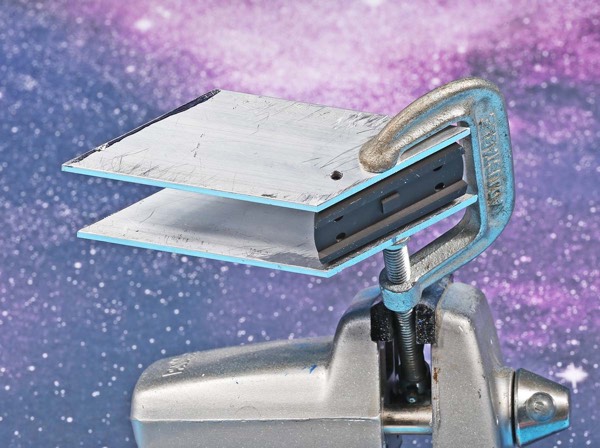
The side plates were cut with a hacksaw and “milled” to size with a belt grinder. Drilling the side plate along with the Picatinny rail mount in one go assured accurate alignment. The holes were drilled with an 8-32 tap drill bit — not a clearance bit. After the left plate was done, Ray clamped the right plate to it and used the holes from the left plate as a template for drilling the holes on the right plate. The hole in the plate was then used as a drill guide for the next screw hole. Ray threaded each hole before drilling the next hole. Screws do not get in the way of drilling like the clamp.

Mount assembled: Note the screws on the right plate are still long — the belt grinder worked well to adjust the screw length.

The top plate is 0.25" thick. Ray used #6-32 screws as #8 screws were too big. This sort of free hand work requires diligence to achieve straight holes. Each hole was drilled and then tapped through the side plate to maintain alignment. A clearance hole was then drilled (carefully) through just the side plate and a screw was tightened down after the hole was taped. Drilling and taping were repeated for each hole in sequence. It was cold in Ray’s garage!

According to Ray, the set-up is finished for “testing” but he’ll need to run a lot more ammo through the gun before he decides if he likes it or not. If he does, he’ll clean it up and get rid of the pointy bits.

Black Hills HoneyBadger ammo has less recoil than normal 230-gr. ammo so Ray didn’t suffer vertical stringing during test shooting. He managed respectable accuracy even with the one flyer. The “homemade” red dot mount actually worked! Cobbling something like this together might let you see if it makes a difference for you in a certain or oddball gun. Then, if so, you could try to find a factory-manufactured mounting system if available. Either way, DIY projects like this are both fun and satisfying.
For more info: www.